H9PPDT8037Body Worn PC with Radio Lan
Symbol Technologies Inc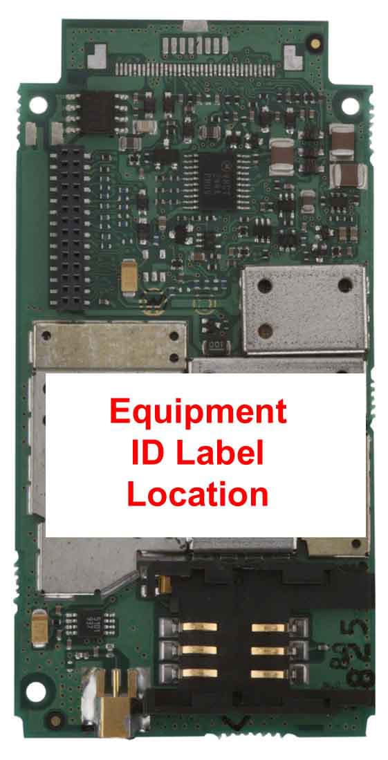
Click to zoom
Application Details
- Equipment Class
- PCT - PCS Licensed Transmitter worn on body
- Date of Grant
- Apr 10, 2003
- Application Purpose
- Original Equipment
- Date of Application
- Apr 10, 2003
- Equipment Note
- Body Worn PC with Radio Lan
- Frequency Range
- 1850.20000000 - 1909.80000000
- Company
- Symbol Technologies Inc
- Country
- United States
Documents & Files
Document Text
Text extracted from the exhibit documents filed with the FCC. Open a document above to read the original.
Users Manual
PDT 80XX WWAN F o r I n t e r n a l U s e O n l y PDT 80XX WWAN © 2003 SYMBOL TECHNOLOGIES, INC. All rights reserved. Symbol reserves the right to make changes to any product to improve reliability, function, or design. Symbol does not assume any product liability arising out of, or in connection with, the application or use of any product, circuit, or application described herein. No license is granted, either expressly or by implication, estoppel, or otherwise under any patent right or patent, covering or relating to any combination, system, apparatus, machine, material, method, or process in which Symbol products might be used. An implied license only exists for equipment, circuits, and subsystems contained in Symbol products. Symbol and the Symbol logo are registered trademarks of Symbol Technologies, Inc. Other product names mentioned in this manual may be trademarks or registered trademarks of their respective companies and are hereby acknowledged. Symbol Technologies, Inc. One Symbol Plaza Holtsville, N.Y. 11742-1300 http://www.symbol.com Patents This product is covered by one or more of the following U.S. and foreign Patents: U.S. Patent No. 4,593,186; 4,603,262; 4,607,156; 4,652,750; 4,673,805; 4,736,095; 4,758,717; 4,760,248; 4,806,742; 4,816,660; 4,845,350; 4,896,026; 4,897,532; 4,923,281; 4,933,538; 4,992,717; 5,015,833; 5,017,765; 5,021,641; 5,029,183; 5,047,617; 5,103,461; 5,113,445; 5,130,520; 5,140,144; 5,142,550; 5,149,950; 5,157,687; 5,168,148; 5,168,149; 5,180,904; 5,216,232; 5,229,591; 5,230,088; 5,235,167; 5,243,655; 5,247,162; 5,250,791; 5,250,792; 5,260,553; 5,262,627; 5,262,628; 5,266,787; 5,278,398; 5,280,162; 5,280,163; 5,280,164; 5,280,498; 5,304,786; 5,304,788; 5,306,900; 5,324,924; 5,337,361; 5,367,151; 5,373,148; 5,378,882; 5,396,053; 5,396,055; 5,399,846; 5,408,081; 5,410,139; 5,410,140; 5,412,198; 5,418,812; 5,420,411; 5,436,440; 5,444,231; 5,449,891; 5,449,893; 5,468,949; 5,471,042; 5,478,998; 5,479,000; 5,479,002; 5,479,441; 5,504,322; 5,519,577; 5,528,621; 5,532,469; 5,543,610; 5,545,889; 5,552,592; 5,557,093; 5,578,810; 5,581,070; 5,589,679; 5,589,680; 5,608,202; 5,612,531; 5,619,028; 5,627,359; 5,637,852; 5,664,229; 5,668,803; 5,675,139; 5,693,929; 5,698,835; 5,705,800; 5,714,746; 5,723,851; 5,734,152; 5,734,153; 5,742,043; 5,745,794; 5,754,587; 5,762,516; 5,763,863; 5,767,500; 5,789,728; 5,789,731; 5,808,287; 5,811,785; 5,811,787; 5,815,811; 5,821,519; 5,821,520; 5,823,812; 5,828,050; 5,848,064; 5,850,078; 5,861,615; 5,874,720; 5,875,415; 5,900,617; 5,902,989; 5,907,146; 5,912,450; 5,914,478; 5,917,173; 5,920,059; 5,923,025; 5,929,420; 5,945,658; 5,945,659; 5,946,194; 5,959,285; 6,002,918; 6,021,947; 6,029,894; 6,031,830; 6,036,098; 6,047,892; 6,050,491; 6,053,413; 6,056,200; 6,065,678; 6,067,297; 6,082,621; 6,084,528; 6,088,482; 6,092,725; 6,101,483; 6,102,293; 6,104,620; 6,114,712; 6,115,678; 6,119,944; 6,123,265; 6,131,814; 6,138,180; 6,142,379; 6,172,478; 6,176,428; 6,178,426; 6,186,400; 6,188,681; 6,209,788; 6,209,789; 6,216,951; 6,220,514; 6,243,447; 6,244,513; 6,247,647; 6,308,061; 6,250,551; 6,295,031; 6,308,061; 6,308,892; 6,321,990; 6,328,213; 6,330,244; 6,336,587; 6,340,114; 6,340,115; 6,340,119; 6,348,773; 6,380,949; 6,394,355; D305,885; D341,584; D344,501; D359,483; D362,453; D363,700; D363,918; D370,478; D383,124; D391,250; D405,077; D406,581; D414,171; D414,172; D418,500; D419,548; D423,468; D424,035; D430,158; D430,159; D431,562; D436,104. Invention No. 55,358; 62,539; 69,060; 69,187, NI-068564 (Taiwan); No. 1,601,796; 1,907,875; 1,955,269 (Japan); European Patent 367,299; 414,281; 367,300; 367,298; UK 2,072,832; France 81/03938; Italy 1,138,713 rev. 06/02 F o r I n t e r n a l U s e O n l y 1 Quick Reference Introduction Congratulations on your purchase of Symbol Technologies’ PDT 8000 WAN Terminal! Its unique combination of features make this product superior for use in a wide range of applications. These features include: •Microsoft ® Windows ® Pocket PC 2002 operating system •RF communication via a wide area network (PDT 8037/ 8056) or Symbol’s Spectrum24 ® wireless network (PDT 8056) •USB Client •1-Dimensional barcode scanning capability •3.9 inch 1/4 VGA Color LCD •Touch screen •Printing support •IrDA-compliant interface for printing and communications. About This Guide This guide describes how to set up and use the terminal. Within this guide, the term PDT 8000 refers to the Spectrum24/WAN and WAN only versions of the terminal. Specific topics covered include: •Accessories on page 3 •Parts of the Terminal on page 4 •Installing the SIM Card on page 6 •Inserting a Compact Flash Storage Card (PDT 8037 only) on page 7 •Removing a Compact Flash Storage Card on page 7 •Inserting an MMC/SD Storage Card on page 8 •Removing an MMC/SD Storage Card on page 8 •Installing Batteries on page 9 •Charging the Battery on page 10 •Starting the Terminal on page 12 •Adjusting the Backlight on page 14 •Using a Headset on page 14 F o r I n t e r n a l U s e O n l y 2 PDT 80XX WWAN •Using the Keyboard on page 15 •Using the Stylus on page 16 •Today Screen on page 17 •Navigation Bar and Command Bar on page 18 •Input Methods on page 19 •Scanning with the Terminal on page 22 •Resetting Your Terminal on page 22 •Host Communications on page 23 •LED Indicators on page 24 •Maintaining the Terminal on page 25 •Troubleshooting on page 26 •Regulatory Information on page 33 •Service Information on backcover. The PDT 8000 Series Product Reference Guide (p/n 72-58169-xx) details the applications available for the terminal. For the latest version of this guide go to: http://www.symbol.com/manuals. F o r I n t e r n a l U s e O n l y 3 Quick Reference Accessories Each terminal requires one 7.4 volt 1130 mAh prismatic lithium-ion battery. The following optional accessories are available from Symbol Technologies: •Additional lithium-ion battery (p/n 21-54882-01) •Stylus for performing pen functions (11-55475-05) •Cables: -Snap-On DEX cable (p/n CBL-8000-100-DEX) -Snap-…
Text truncated - open the document above for the full version.
Cover Letter(s)
APPLICANT: MOTOROLAFCC ID: IHDT6AC1 Exhibit 13 June 1, 2000 CONFIDENTIALITY REQUEST CONTAINED WITHIN Federal Communications Commission Authorization and Evaluation Division 7435 Oakland Mills Road Columbia, Maryland 21046 Re: Application for PCS Transceiver Certification Gentlemen: Application: Motorola, Inc., Personal Communications Sector, 600 N. U.S. Highway 45, Libertyville, Illinois 60048-1286 herein submits: Application for Equipment Authorization (FCC Form 731-October 1992 with integrated Fee Processing Form, Fee Codes EFT and EBC), application fee in the amount of $610, and Exhibits; for Certification of a PCS Transceiver, FCC ID: IHDT6AC1. Motorola is also the manufacturer of this equipment. Confidentiality: Pursuant to Section 0.459 of the Commission's rules (CFR 47), Motorola requests confidentiality for portions of the material contained in this application and that the identified material be withheld from public inspection following the grant of this authorization. This material contains Motorola's trade secrets and confidential information that Motorola does not customarily release to the public and which is otherwise not generally available to the public. Confidentiality is requested for the following exhibits: • Exhibit 4 Block Diagrams • Exhibit 5 Schematics • Exhibit 12 Operational Description Description: This equipment is a GSM Embedded Module, which operates in the 1900 MHz PCS band. It can transfer data or voice over a GSM network. Model differences are dependent upon housing and external connector variations. Contact Information: Please contact me by telephone at (847) 523-6167 or by e-mail ([email protected]), if there are questions or additional information needed concerning this filing. Regards, Andrew J. Bachler FCC Liaison Personal Communications Sector 600 N. U.S. Highway 45 Libertyville, IL 60048-5343
External Photos
Exhibit 3 See test report in Exhibit 6
ID Label/Location Info
PDT 80XX WWAN PDT 8056PDT 8037 Product Labels SYMBOL TECHNOLOGIES INC., HOLTSVILLE N.Y. 11742 P/N: PDT8056-XXXXXXXXX MFD: XXXXXXXX,XXXX S/N BAR CODE IMEI:XXXXXXXXXXXXXXX XXXX MADE IN XXXXXX SN: XXXXXXXXXXXXXXXX IMEI BAR CODE SEE QUICK REFERENCE GUIDE FOR PATENT AND RADIO INFORMATION. FCC ID : H9PPDT8056 IC: 1549D-PDT8056 TYPE: PDT8056 THIS PRODUCT CONTAINS APPROVED RADIO MODULES N410 0168 SYMBOL TECHNOLOGIES INC., HOLTSVILLE N.Y. 11742 P/N: PDT8037-XXXXXXXXX S/N BAR CODE IMEI:XXXXXXXXXXXXXXX XXXX MFD: XXXXXXXXX,XXXX MADE IN XXXXXX SN: XXXXXXXXXXXXXXXX IMEI BAR CODE SEE QUICK REFERENCE GUIDE FOR PATENT AND RADIO INFORMATION. FCC ID : H9PPDT8037 IC: 1549D-PDT8037 TYPE: PDT8037 THIS PRODUCT CONTAINS AN APPROVED RADIO MODULE N410 0168
Internal Photos
Exhibit 9 See test report in Exhibit 6
Internal Photos
APPLICANT: MOTOROLA, INC. FCC ID: IHDT6AC1 EXHIBIT 3A Typical Non-Housed Unit (Bottom View) Typical Non-Housed Unit (Top View Showing ID Label on Shields) APPLICANT: MOTOROLA, INC. FCC ID: IHDT6AC1 EXHIBIT 3B Typical Housed Unit (Bottom View) Typical Housed Unit (Top View Showing ID Label )
Parts List/Tune Up Info
APPLICANT: MOTOROLA, INC.FCC ID: IHDT6AC1 EXHIBIT 10 TRANSCEIVER ADJUSTMENTS/TUNE-UP PROCEDURE There are no user accessible adjustments or tuning in this portable cellular transceiver. All necessary adjustments and tuning are performed during manufacture of the product. Any adjustments or tuning after service or repair are done as part of that process as special equipment is required to perform such adjustments.
RF Exposure Info
TEST REPORT In support of the Application for Grant of Equipment Authorisation of the Symbol Portable Data Terminal, PDT8056 FCC ID: H9PPDT8056 & H9PPDT8037March 2003 TUV Product Service Ltd. Segensworth Road, Titchfield Fareham, Hampshire, United Kingdom, PO15 5RH Tel: +44(0)1329 443300, Fax: +44(0)1329 443331 www.tuvps.co.uk Report Number WS610827 Rev 2Page 1 of 52 REPORT ON:Specific Absorption Rate testing of the Symbol PDT8056 Dual Mode (Tri-Band GSM (GPRS) / 802.11b RLAN) Portable Data Terminal with Symbol Headset. Report No: WS610827 FCC ID:H9PPDT8056 & H9PPDT8037 PREPARED FOR:Symbol Technologies Inc One Symbol Plaza Holtsville NY 11742-1300 ATTESTATION:The wireless portable devices described within this report have been shown to be capable of compliance for localised specific absorption rate (SAR) for General Population/Uncontrolled Exposure Limits as defined in Supplement C (Edition 01-01) to OET Bulletin 65 (Edition 97-01) of 1.6 W/kg. The devices were tested in accordance with the measurement procedures specified in Supplement C (Edition 01-01) to OET Bulletin 65 (Edition 97-01) and IEEE1528-200x (Draft December 2002). I attest to the accuracy of data. All measurements reported herein were performed by me or were made under my supervision and are correct to the best of my knowledge and belief. I assume full responsibility for the completeness of these measurements. A. Miller Senior SAR Test Engineer APPROVED BY: M Jenkins Wireless Group Leader DATED:26 th March 2003 DISTRIBUTION:Symbol Technologies IncCopy No: 1 Symbol Technologies Inc (CD ROM).Copy No(s): 2 BABT Copy No.: 3 Copy No.: 1 Note: The test results reported herein relate only to the item tested as identified above and on the Status Page. Report 610827 Re-issued to typographical errors FCC ID: H9PPDT8056 & H9PPDT8037 Report Number WS610827 Rev 2Page 2 of 52 CONTENTS EXECUTIVE SUMMARY3 1.1Status4 1.2Summary5 1.3Test Result Summary6 TEST DETAILS8 2.1Test Equipment9 2.2Test Software9 2.3Dielectric Properties of Simulant Liquids10 2.4Test Conditions11 2.5Measurement Uncertainty11 2.6SAR Measuring System12 Probe and Amplifier Specification Probe Calibration SAR Measurement Procedure 2.7Draft IEEE std 1528 Test Positions30 OET65(c) Flat Phantom Test Position – Graphical Representation 2.8SAR Distributions (Area Scans – 2D)32 2.9Test Positional Photographs48 2.10Record Photographs49 For copyright details see page 52 of 52. FCC ID: H9PPDT8056 & H9PPDT8037 Report Number WS610827 Rev 2Page 3 of 52 EXECUTIVE SUMMARY Specific Absorption Rate testing of the Symbol PDT8056 Dual Mode (Tri-Band GSM (GPRS) / 802.11b RLAN) Portable Data Terminal with Symbol Headset. PROJECT MANAGER: M. GLASSPOOL FCC ID: H9PPDT8056 & H9PPDT8037 Report Number WS610827 Rev 2Page 4 of 52 1.1STATUS MANUFACTURING DESCRIPTIONPortable Data Terminal STATUS OF TESTSpecific Absorption Rate Testing APPLICANTSymbol Technologies Inc MANUFACTURERSymbol Technologies Inc TYPE OR MODEL NUMBERPDT8056 HARDWARE VERSIONRev 4 MULTISLOT CLASSClass 2 GSM/GPRS TRI-BANDE-GSM 900 Class 4 DCS1800 Class 1 PCS1900 Class 1 RADIO LAN2.4GHz Direct Spread Spectrum SOFTWARE VERSIONE6.14.28 SERIAL NUMBERIMEI350030950616014 BATTERY MANUFACTURERSymbol Technologies Inc TYPE OR MODEL NUMBER21-54882-01 TEST SPECIFICATIONS: Federal Communications Commission, Code of Federal Regulations, Title 47 (CFR47), Vol. 1, Chapter 1, Part 2 (§2.1091 and §2.1093). Federal Communications Commission (FCC) OET Bulletin 65c, Edition 01-01, Evaluating Compliance with FCC Guidelines for Human Exposure to Radiofrequency Electromagnetic Fields – Additional Information for Evaluating Compliance of Mobile and Portable Devices with FCC Limits for Human Exposure to Radiofrequency Emissions CENELEC EN 50360: July 2001, Product Standard to demonstrate the compliance of mobile phones with the basic restrictions related to human exposure electromagnetic (300 MHz - 3 GHz). CENELEC EN 50361: July 2001, Basic standard for the measurement of Specific Absorption Rate related to human exposure to electromagnetic fields from mobile phones (300 MHz - 3 GHz). RSS-102 Issue 1 (Provisional) September 25, 1999: Evaluation Procedure for Mobile and Portable Radio Transmitters with respect to Health Canada’s Safety Code 6 for Exposure of Humans to radio Frequency Fields REFERENCES: IEEE 1528 –200X: DRAFT Recommended Practice for Determining the Peak Spatial-Average Specific Absorption Rate (SAR) in the Human Body Due to Wireless Communications Devices: Experimental Techniques Council Recommendations 1999/519/EC on the limitations of exposure of the general public to electromagnetic fields (0 Hz - 3 GHz) annex II. BABT REGISTRATION NUMBER:WS610827. RECEIPT OF TEST SAMPLES:14 th March 2003. START OF TEST:20 th March 2003. FINISH OF TEST:22 nd March 2003. FCC ID: H9PPDT8056 & H9PPDT8037 Report Number WS610827 Rev 2Page 5 of 52 1.2SUMMARY The PDT8056 is a Portable Data Terminal, which offers Tri band GSM/GPRS and 2.4GHz Wireless LAN (11Mbps DSSS) connectivity. The data terminal utilises the Motorola G18 GSM/GPRS L Series module (Hardware Version g18_vE6.14.28.00) to offer GSM voice communication via the Symbol supplied headset. Also installed is the approved symbol Compact Flash LA-4137 Wireless LAN radio card. These radios do not transmit simultaneously. The PDT8037 is a ‘Sub Equip’ of the PDT8056. The PDT8037 is a Portable Data Terminal, which offers Tri band GSM/GPRS connectivity, in this model the Symbol Compact Flash RLAN radio card is not installed. No testing was performed on this unit. SAR testing was first performed using a Flat Phantom dimensions 220mmx200mmx150mm and with a sidewall thickness of 2.0mm. The phantom was filled to a depth of 150mm with 2450MHz Body simulant liquid. The dielectric properties were in accordance with the requirements for the dielectric properties specified in Supplement C (Edition 01-01) to OET Bulletin 65 (Edition 97-01). SAR testing was carried out at the top, middle and bottom frequency of each of t…
Text truncated - open the document above for the full version.
Test Report
TEST REPORT In support of the Application for Grant of Equipment Authorisation of the Symbol Technologies Portable Data Terminal, PDT8056 FCC ID: H9PPDT8056 & H9PPDT8037March 2003 TÜV Product Service Limited Segensworth Road, Fareham Hampshire, United Kingdom PO15 5RH Telephone: +44 (0)1329 443300 Website:www.tuvps.co.uk REPORT NUMBER OR610827/2PAGE 1 OF 46 Equipment:PDT8056 FCC ID:H9PPDT8056 & H9PPDT8037 Specification:47 CFR 2 & 47 CFR 24 Applicant:Symbol Technologies Inc One Symbol Plaza NY11742 United States Manufacturer:As above Manufacturer’s Representative:Mr Marco Belli Approved by: C GOULD Chief Engineer Dated:21 st March 2003 Start of Test:6 h March 2003 Completion of Test:13 th March 2003 Report Distribution:Symbol TechnologiesMr M BelliCopy No. 1 BABTCopy No’s. 2 & 3 Copy No: ENGINEERING STATEMENT I ATTEST: the measurements shown in this report were made in accordance with the procedures indicated, and that the emissions from this equipment were found to be within the applicable limits. I assume full responsibility for the accuracy and completeness of these measurements. On the basis of the measurements made, the equipment tested is capable of operation in accordance with the requirements of Part 2, and Part 24 of the FCC Rules under normal use and maintenance. Chris Gould Chief Engineer FCC ID: H9PPDT8056 & H9PPDT8037 REPORT NUMBER OR610827/2PAGE 2 OF 46 CONTENTS:- Page No. Introduction3 Location of Testing3 Test Equipment and Ancillaries Used For Test3 Description of Equipment Under Test Configuration5 List of Performed Measurements5 The list of measured parameters covering SubclauseParameter to be measured 47 CFR2.1053Radiated Emissions6 Photographs of test sample(s) PDT805610 Photographs of test sample(s) PDT803729 Manufacturers Label Drawing – PDT805628 Manufacturers Label Drawing – PDT803745 For copyright details see Page 46 of 46. FCC ID: H9PPDT8056 & H9PPDT8037 REPORT NUMBER OR610827/2PAGE 3 OF 46 INTRODUCTION The information contained within this report is intended to show verification of compliance of the Symbol Technologies PDT8056 to the requirements of 47 CFR 2 and 47 CFR 24. PDT8056 The PDT8056 is a Portable Data Terminal, which offers Triband GSM/GPRS and 2.4GHz Wireless LAN (11Mbps DSSS) connectivity. The terminal utilizes the Motorola G18 GSM/GPRS module which is approved to FCC Part 24. The FCC Identifier of the module is IHDT6AC1, the date of the FCC Grant was 8 th January 2000. Also installed is the Symbol Compact Flash LA-4137 Wireless LAN radio card which is approved to FCC Part15. The FCC Identifier of the module is H9PLA4137P, the date of the FCC grant was 21 st March 2002. This report covers limited testing on the PDT8056 to cover the integration of the Motorola GSM/GPRS radio module. PDT8037 The PDT8037 is a “sub equip” of the PDT8056. The PDT8037 is a Portable Data Terminal which offers Triband GSM/GPRS connectivity, in this model the Symbol Compact Flash RLAN radio card is NOT installed. Photographs of the unit are contained within this report. No testing was performed on this unit. LOCATION OF TESTING TUV Engineer, Mike Timberlake and Phil Harrison, conducted all testing at the premises of TUV Product Service, Segensworth Road, Fareham, Hampshire, PO15 5RH. Radiated Emissions measurements were performed in a 3 metre Anechoic Chamber. A complete site description is on file with the FCC Laboratory Division, Registration Number: 90987. See Annex A. TEST EQUIPMENT AND ANCILLARIES USED FOR TEST NoInstrument/AncillaryTypeManufacturerEMC No. 1EMI ReceiverRhode & SchwartzESIB 402917 2Turntable and ControllerHD GmbhHD 050- 3Antenna MastEMCO2070- 4Antenna Mast ControllerEMCO2090- 5Screened Room 5--2533 6Pre-Amplifier, (8-18GHz)AvantekAWT-180361081 7Pre-Amp (1-8GHz)MiteqAMF-3D-001080-18-13P2457 8Horn (1-18GHz)EMCO31152397 9Signal GeneratorHewlett Packard8673B2551 10Test ReceiverRohde & SchwarzESIB402917 11Pre-Amplifier, (18-26GHz)AvantekAMT-26177-332072 12Horn (18 – 26GHz)Flann2024-201396 13High Pass FilterRLCF-100-4000-5-R4468 14Microwave Co-axial Adaptor Flann20093SF402917 Table 1 FCC ID: H9PPDT8056 & H9PPDT8037 REPORT NUMBER OR610827/2PAGE 4 OF 46 TEST EQUIPMENT AND ANCILLARIES USED FOR TEST (Continued) Note(s) 1)All items are calibrated annually except where labelled T/U (Traceability Unscheduled). These items are calibrated within the test configurations using calibrated equipment. 2) Throughout the test report the test equipment used for each test is referenced using the number indicated in the table above. INSTRUMENTATION USED FOR EXERCISING THE EUT InstrumentManufacturerType NoINV No GSM Test SetHewlett Packard8922M3803 Table 2 FCC ID: H9PPDT8056 & H9PPDT8037 REPORT NUMBER OR610827/2PAGE 5 OF 46 DESCRIPTION OF EQUIPMENT UNDER TEST The PDT8056 is a handheld computer terminal with a tri band GSM/GPRS radio module used for inventory control purposes. The equipment under test is made up of the following component parts. ModuleVendor Kit Number Serial Number Portable Data TeminalSymbol Technologies IncPDT8056ALP65919 Table 3 LIST OF PERFORMED MEASUREMENTS USING THE CONFIGURATION IN TABLE 3 i) Power Output ii) Radiated Emissions FCC ID: H9PPDT8056 & H9PPDT8037 REPORT NUMBER OR610827/2PAGE 6 OF 46 Test CaseRadiated Emissions Test Date11 th March 2003 Rule Parts24.238 SYSTEM CONFIGURATION DURING EMC TESTING The Symbol PDT8056 with GSM/GPRS Radio Module was powered by its own internal battery. A communication link was established between the EUT and a Digital Radiocommuncations Test Set. TEST PROCEDURE Testing to the requirements of FCC Part 24, Section 24.238, Emission Limits, was carried out on the Measurement Test Facility detailed in Annex A. In order to determine the Radiated Emission Limits, measurements of transmitter power (P) were first carried out on the top and bottom channels using a peak detector, and the results are shown in Table 4. A preliminary profile of the Radiated Electric Field Emissions was obtained by operating the Equipment Under Test …
Text truncated - open the document above for the full version.
Test Report
APPLICANT MOTOROLA INC. FCC ID:IHDT6AC1 Exhibit 6 1 TEST REPORT Exhibit Summary: EXHIBIT6 contains worst case measurement data that was taken on five different D15 Module configuration, listed below: 1. D15 DV (DV= Data & Voice) Standard 2. D15 DV Slim 3. D15 DVG Slim (DVG= Data, Voice, GPS) 4. D15 DV Board only (Vertical version) 5. D15 DV Board only (Horizontal version) Contents: RF Power Output.....................................................6A Final Amplifier Voltages and Currents......................6B Radiated Spurious Emission...................................6C Occupied Bandwidth...............................................6D Conducted Spurious Emissions...............................6E Frequency Stability..................................................6F APPLICANT MOTOROLA INC. FCC ID:IHDT6AC1 Exhibit 6A 2 RF Output Power Exhibit Summary: EXHIBIT 6A contains both average and peak output powers for the mobile station. The peak power results are presented in tabular form which illustrates the deviation in power with respect to the average value. In all cases, the peak output power is within the required mask (this mask is specified in the JTC standards, TIA PN3389 Vol. 1, Chap. 7, and is not an FCC requirement). Contents: Method of Measurement..............................................2 Measurement Limit......................................................2 Power Measurements..................................................2 Method of Measurement: 1.Setup the mobile station for maximum output power with pseudo random data. 2.Use HP 8991A Peak Power Analyzer to obtain peak and average output power levels. 3.Repeat measurements for carrier frequencies at 1850.2 MHz, 1880.2 MHz, and 1909.8 MHz. Channels 512, 662, and 810 respectively (bottom, middle, and top of operational frequency range). Measurement Limits: Table 6.1 PowerNominal Peak StepOutput PowerTolerance (dBm)(dB) 030+/- 2 Power Measurements: Table 6.2 FrequencyPowerPeakAverage (MHz)StepOutput PowerOutput Power (dBm)(dBm) 1850.2029.920.87 1880.2029.520.47 1909.8028.7519.72 APPLICANT MOTOROLA INC. FCC ID:IHDT6AC1 Exhibit 6B 3 Final Amplifier Voltage and Currents Exhibit Summary: EXHIBIT 6B below contains the voltages and currents applied to the TX Driver and TX Final Power Amplifier for the entire mobile station operating power range. PowerPowerPowerVcc (Q331)Ic (Q331)Vdd (Q380)Id(Q380) StepOutputOutput Spec. (dBm)Meas. (dBm)(VDC)(mA Peak)(VDC)(mA RMS) 0 30 +/-229.94.7244.7290 128 +/-326.724.7224.7260 226 +/-225.14.7184.7240 324 +/-222.954.7164.7230 422 +/-3214.7144.7210 520 +/-319.154.7134.7200 618 +/-317.254.7114.7190 716 +/-315.254.7104.7190 814 +/-313.34.784.7180 912 +/-411.34.774.7180 1010 +/-48.94.75.54.7180 118 +/-47.184.754.7175 126 +/-46.194.74.54.7170 134 +/-45.554.74.34.7170 142 +/-44.14.74.34.7170 150 +/-43.34.74.34.7170 APPLICANT MOTOROLA INC. FCC ID:IHDT6AC1 Exhibit 6C 4 Radiated Spurious Emissions Exhibit Summary: EXHIBIT 6C contains measurement data pertaining to radiated spurious emissions. Contents: Introduction...........................................................................4 Purpose................................................................................4 Radiated Emissions Test Setup............................................5 Radiated Emission Test Procedure......................................5 Test Equipment Utilized for the Radiated Emissions Test....6 Measurement Results...........................................................6 Emission Plot........................................................................7 Appendix A: Sample Calculations.........................................8 Appendix B - Test Equipment...............................................9 Introduction The following steps outline the procedure used to measure the radiated emissions from the mobile station. The data were taken at L. S. Compliance Inc. Measurement Facility ID Number: 31040/ SIT Located at W66 N220 Commerce Court, Cedarburg, Wisconsin 53012. Test Report Number: 300143 Dates of Testing: March 27-29, 2000. On March 27-29, 2000, a series of Radiated Emissions tests were performed on a sample model of the Motorola D15 family of modules for Cellular Telephone. These tests were performed using the test procedures outlined in ANSI C63.4-1992 for intentional radiators, as called for in section 2.1033 for a type accepted device, and in accordance with the limits set forth in FCC Part 15.109, Part 24, and 22.917e. These tests were performed by Kenneth L. Boston, PE, of L. S. Compliance, Inc. and witnessed by Reuven Konevky of Motorola. Purpose The above mentioned tests were performed in order to determine the compliance of the test sample with limits contained in various provisions of Title 47 CFR, including: 2.10512.105315.10924.238 22.917 All radiated emissions tests were performed to measure the emissions in the frequency bands described by the above sections, and to determine whether emissions are below the limits established by the above sections. These tests were APPLICANT MOTOROLA INC. FCC ID:IHDT6AC1 Exhibit 6C 5 performed in accordance with the procedure described in the American National Standard for methods of measurement of Radio-Noise Emissions from Low-Voltage Electrical and Electronic Equipment in the Range of 9 kHz to 40 GHz (ANSI C63.4- 1992). Another document used as reference for the EMI receiver specification is the International Special Committee on Radio Interference (CISPR) number 16-1 (1993). Radiated Emissions Test Setup The test sample was operated within the 3 meter Semi-Anechoic, FCC listed chamber located at L.S. Compliance in Cedarburg, WI. The sample was placed on an 80cm high small wooden pedestal, centered on the flush-mounted 2m diameter metal turntable. The test sample was configured to run in a continuous transmit mode during the Radiated measurements. The test sample was set to operate on one of three standard channels within the Cellular frequency assig…
Text truncated - open the document above for the full version.
Test Setup Photos
Exhibit 7 See test report in Exhibit 6
Contact Information
Applicant
Qianlin Zhou(Regulatory Specialist)
Test Firm
TUV SUD Product ServiceJensen Adams
Technical Specifications
| # | Rule Parts | Frequency Range | Power Output | Emission | Tolerance |
|---|---|---|---|---|---|
| 1 | 24E | 1.85 GHz - 1.91 GHz | 1 W | 250KGXW | 2.5000000000 % |
Other Applications from Symbol Technologies Inc

H9PCCHUB1
Jun 30, 2015Customer Concierge
Equipment Class
NII - Unlicensed National Information Infrastructure TX
H9PAP7562
May 10, 2015802.11 abgn/ac Access Point
Equipment Class
DTS - Digital Transmission System
H9PTC75AH
Mar 26, 2015Touch Computer
Equipment Class
NII - Unlicensed National Information Infrastructure TX
H9PRA1202
Sep 24, 2014UHF Narrowband Radio Module
Equipment Class
TNB - Licensed Non-Broadcast Station Transmitter
H9PEMG101
Aug 26, 2014802.15.4 Gateway
Equipment Class
DTS - Digital Transmission System