H9PPDT8137PCS GSM Handheld Terminal
Symbol Technologies Inc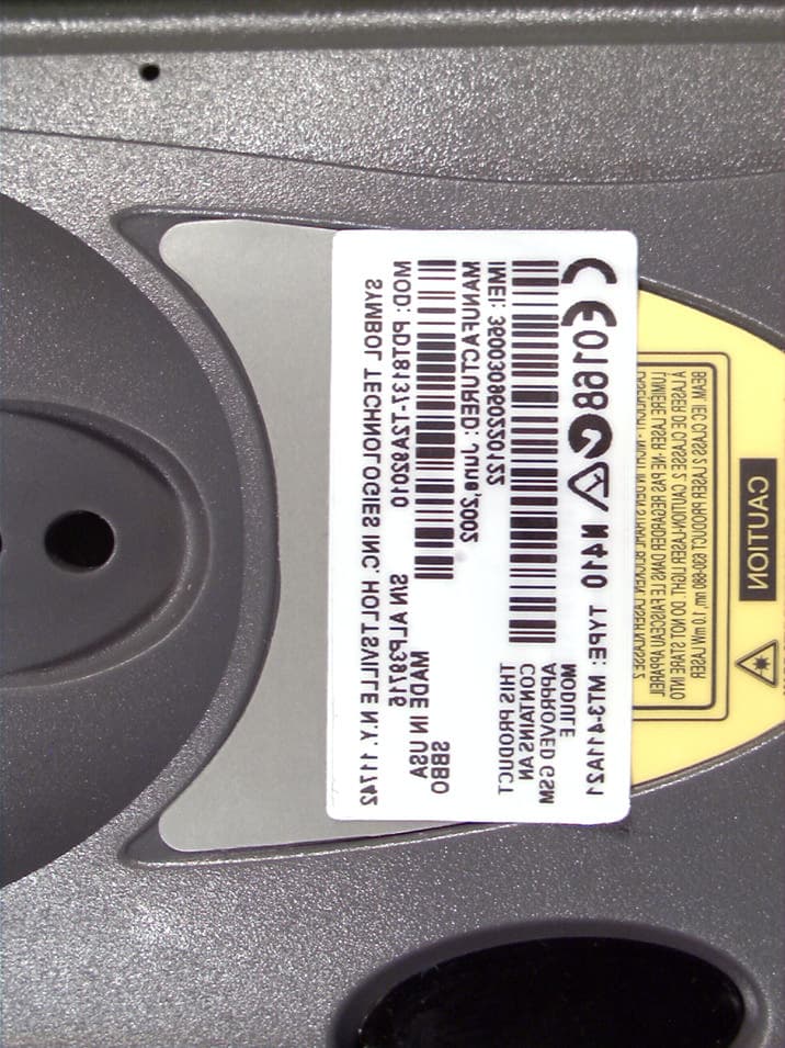
Click to zoom
Application Details
- Equipment Class
- PCT - PCS Licensed Transmitter worn on body
- Date of Grant
- Aug 18, 2002
- Application Purpose
- Original Equipment
- Date of Application
- Aug 15, 2002
- Equipment Note
- PCS GSM Handheld Terminal
- Frequency Range
- 1850.20000000 - 1909.80000000
- Company
- Symbol Technologies Inc
- Country
- United States
Documents & Files
Document Text
Text extracted from the exhibit documents filed with the FCC. Open a document above to read the original.
Users Manual
For more information about RF exposure, please visit the FCC website at www.fcc.gov FCC RF EXPOSURE INFORMATION In August 1996 the Federal Communications Commission (FCC) of the United States with its action in Report and Order FCC 96-326 adopted an updated safety standard for human exposure to radio frequency electromagnetic energy emitted by FCC regulated transmitters. Those guidelines are consistent with the safety standard previously set by both U.S. and international standards bodies. The design of this phone complies with the FCC guidelines and these international standards. Use only the supplied or an approved antenna. Unauthorized antennas, modifications, or attachments could impair call quality, damage the phone, or result in violation of FCC regulations. Do not use the phone with a damaged antenna. If a damaged antenna comes into contact with the skin, a minor burn may result. Please contact your local dealer for replacement antenna. Body-worn Operation This device was tested for typical body-worn operations with the Holster providing a minimal spacing of 2.5 cm. from the body to the back of the terminal/antenna. To maintain compliance with FCC RF exposure compliance requirements, use only belt-clips, holsters or similar accessories that maintain a 2.5 cm. separation distance between the user’s body and the back of the terminal, including the antenna. The use of third-party belt-clips, holsters and similar accessories should not contain metallic components in its assembly. The use of accessories that do not satisfy these requirements may not comply with FCC RF exposure compliance requirements, and should be avoided. WARNING! Read this information before using your phone PDT 810 9 Troubleshooting on page 28. Scanning with the PDT 8100 on page 24 Resetting Your PDT 8100 Terminal on page 24 Host Communications on page 26 Maintaining the PDT 8100 on page 27 The PDT 8100 Product Reference Guide (p/n 72-50932-xx), available from your Reseller or from Symbol Technologies, details the applications available for the PDT 8100. Accessories Each PDT 8100 requires one 1550 mAh lithium-ion battery. The following optional accessories are available from Symbol Technologies: Additional lithium-ion battery Cables: Stylus for performing pen functions - Serial charging cable - DEXcable - Autocharge cable - Snap-on printer cable Single-slot cradle Four-slot cradle Vehicle cradle lrDA compliant printer Magnetic stripe reader Carrying case. 2
Attestation Statements
July 29, 2002 Federal Communications Commission Authorization and Evaluation Division Equipment Authorization Branch 7435 Oakland Mills Road Columbia, MD 21 046 To whom it may concern: We, the undersigned, hereby authorize PCTEST Engineering Laboratory Inc., to act on our behalf in all matters relating to applications for equipment authorization, including the signing of all documents relating to these matters. Any and all acts carried out by PCTEST Engineering Laboratory, Inc. on our behalf shall have the same effect as acts of our own. We also hereby certify that no party to this application is subject to a denial of benefits, including FCC benefits, pursuant to Section 5301 of the Anti-Drug Abuse Act of 1988, 21 U.S. C. 862. S i ncere I y, Sandy Mazzola Regulatory Engineer Symbol Technologies Inc. 1 Symbol Plaza Holtsville, NY 1 1742-1 300 Phone: (631) 738-5373 Fax: (631) 738 -331 8 or (631) 738-391 5 E - m a i I : mazzolas@-s~mbol..com BYMEOLIECHNC3LQOIEB. INC. One Symbol Plaza, HoiGsvllle, NY 1 1742-1300 516 730-2400 Web slce: http:/lwww.symbol.oorn
Attestation Statements
July 29, 2002 Federal Communications Commission Authorization and Evaluation Division Equipment Authorization Branch 7435 Oakland Mills Road Columbia, MD 2 1046 Re: Symbol Technologies FCC ID: H9PPDT8137 Confidentiality Dear Reviewer, Symbol Technologies (“Symbol”), requests that the Block Diagram, Schematics, and operational Description exhibits of the referenced application be withheld from routine availability for public inspection pursuant to Section 0.459 of the Commissions Rules an Freedom of Information Act (“FOIA) Exemption 4, 5 U.S.C. 552 (b) (4). ‘These exhibits consist of “trade secrets (or) commercial or financial information obtained from a person and privileged or confidential” 5 U.S.C. 552 (b) (4), and is therefore entitled to protection from disclosure under FOIA. The documents in question contain trade secrets: detailed technical descriptions, specifications and schematics for a product to be offered for sale. This information would give Symbol’s competitors an unearned and unwarranted competitive advantage. The documents contain “commercial information” within the scope of FOIA exemption 4. This information is the product of Symbol’s investment of money, personnel, and other resources. The result of the investment is a fairly earned position in the marketplace. Premature release of the information threatens substantial and unwarranted harm to Symbol’s competitive position. These materials provide particulars on the product design. For these reasons, Symbol has taken pains to keep this technical information confidential, and intends to continue doing so. Symbol customarily witholds this information from persons outside the employ of Symbol and certain of its suppliers and contractors, and even within these groups routinely limits access to persons having a particular need for the information. If the Commissions were to make these documents public, it would be giving away hard won fruits of Symbols labors without compensation. The filing fee that is required for this confidentiality request is included in the check that accompanies this application. If there are any questions about this request, please call me at the number above. Thank you for your attention. Respectfully Submitted, Sandy Mazzola
Cover Letter(s)
July 29, 2002 Federal Communications Commission Equipment Approval Services 7435 Oakland Mills Road Columbia, MD 21046 SUBJECT: SYMBOL TECHNOLOGIES INC. FCC ID: H9PPDT8137 Gentlemen: Attached herewith, on behalf of SYMBOL TECHNOLOGIES INC. is an application for Part 24 Certification of the GSM PCS Handheld Terminal. Attached is the applicant’s Letter of Authorization, Confidentiality Request, measurement report test data and plots, RF Exposure measurement report and data, FCC ID label and location, test setup photographs, internal and external photographs, block diagram (confidential), circuit diagrams & description (confidential), operational description (confidential), parts list & tune-up procedure (confidential), and the user's manual. Should you have any questions or comments concerning the above, please contact the undersigned. cc: Symbol Technologies Inc.
External Photos
© 2002 PCTEST Lab Symbol Technologies, Inc. PCS GSM Handheld Terminal Model: PDT8137 © 2002 PCTEST Lab Symbol Technologies, Inc. PCS GSM Handheld Terminal Model: PDT8137 © 2002 PCTEST Lab Symbol Technologies, Inc. PCS GSM Handheld Terminal Model: PDT8137 © 2002 PCTEST Lab Symbol Technologies, Inc. PCS GSM Handheld Terminal Model: PDT8137 © 2002 PCTEST Lab Symbol Technologies, Inc. PCS GSM Handheld Terminal Model: PDT8137 © 2002 PCTEST Lab Symbol Technologies, Inc. PCS GSM Handheld Terminal Model: PDT8137 © 2002 PCTEST Lab Symbol Technologies, Inc. PCS GSM Handheld Terminal Model: PDT8137 © 2002 PCTEST Lab Symbol Technologies, Inc. PCS GSM Handheld Terminal Model: PDT8137 © 2002 PCTEST Lab Symbol Technologies, Inc. PCS GSM Handheld Terminal Model: PDT8137 © 2002 PCTEST Lab Symbol Technologies, Inc. PCS GSM Handheld Terminal Model: PDT8137
ID Label/Location Info
© 2002 PCTEST Lab FCC ID LABEL & LOCATION LABELLING REQUIREMENTS PER §§ 2.925 The Label shown shall be permanently affixed at a conspicuous location on the device and be readily visible to the user at the time of purchase. (SEE NEXT PAGE) Sample FCC Label Symbol Technologies Inc. Model: PDT8137 FCC ID: H9PPDT8137 IC:1549-PDT8137 This is a sample draft of the label that will be located on the underside of the product. Sandy Mazzola Regulatory Engineer Symbol Technologies Inc Holtsville, N. Y. 11742-1300 Phone: (631) 738-5373 Fax: (631) 738-3318 or (631) 738-3915 E-Mail:[email protected]
Internal Photos
© 2002 PCTEST Lab Symbol Technologies, Inc. PCS GSM Handheld Terminal Model: PDT8137 © 2002 PCTEST Lab Symbol Technologies, Inc. PCS GSM Handheld Terminal Model: PDT8137 © 2002 PCTEST Lab Symbol Technologies, Inc. PCS GSM Handheld Terminal Model: PDT8137 © 2002 PCTEST Lab Symbol Technologies, Inc. PCS GSM Handheld Terminal Model: PDT8137 © 2002 PCTEST Lab Symbol Technologies, Inc. PCS GSM Handheld Terminal Model: PDT8137 © 2002 PCTEST Lab Symbol Technologies, Inc. PCS GSM Handheld Terminal Model: PDT8137 © 2002 PCTEST Lab Symbol Technologies, Inc. PCS GSM Handheld Terminal Model: PDT8137 © 2002 PCTEST Lab Symbol Technologies, Inc. PCS GSM Handheld Terminal Model: PDT8137 © 2002 PCTEST Lab Symbol Technologies, Inc. PCS GSM Handheld Terminal Model: PDT8137 © 2002 PCTEST Lab Symbol Technologies, Inc. PCS GSM Handheld Terminal Model: PDT8137 © 2002 PCTEST Lab Symbol Technologies, Inc. PCS GSM Handheld Terminal Model: PDT8137 © 2002 PCTEST Lab Symbol Technologies, Inc. PCS GSM Handheld Terminal Model: PDT8137 © 2002 PCTEST Lab Symbol Technologies, Inc. PCS GSM Handheld Terminal Model: PDT8137 © 2002 PCTEST Lab Symbol Technologies, Inc. PCS GSM Handheld Terminal Model: PDT8137 © 2002 PCTEST Lab Symbol Technologies, Inc. PCS GSM Handheld Terminal Model: PDT8137
Parts List/Tune Up Info
APPLICANT: MOTOROLA, INC.FCC ID: IHDT6AC1 EXHIBIT 10 TRANSCEIVER ADJUSTMENTS/TUNE-UP PROCEDURE There are no user accessible adjustments or tuning in this portable cellular transceiver. All necessary adjustments and tuning are performed during manufacture of the product. Any adjustments or tuning after service or repair are done as part of that process as special equipment is required to perform such adjustments.
RF Exposure Info
PCTEST ENGINEERING LABORATORY, INC. 6660 — B Dobbin Road • Columbia, MD 21045 • USA Telephone 410.290.6652 / Fax 410.290.6654 http://www.pctestlab.com (email: [email protected]) CERTIFICATE OF COMPLIANCE (SAR EVALUATION) PCTEST SAR REPORT FCC CERTIFICATION Reviewed by: Quality Manager SAR Filename: SAR-220723389.H9P Test Dates: July 30-31, 2002 EUT Type: PCS GSM Handheld Terminal FCC ID: H9PPDT8137 Page 1 of 22 © 2002 PCTEST Engineering Laboratory, Inc APPLICANT NAME & ADDRESS: DATE & LOCATION OF TESTING: Symbol Technologies Inc. Dates of Tests: July 30-31, 2002 1 Symbol Plaza Test Report S/N: SAR.220723390.H9P Holtsville, NY 11742-1300 Test Site: PCTEST Lab, Columbia, MD USA Attn: Sandy Mazzola, Regulatory Engineer CC: Dean La Rosa, Senior Design Engineer FCC ID: H9PPDT8137 APPLICANT: SYMBOL TECHNOLOGIES INC. EUT Type: PCS GSM Portable Data Terminal Tx Frequency: 1850.2 — 1909.8 MHz (PCS GSM) Rx Frequency: 1930.2 — 1989.8 MHz (PCS GSM) Max. RF Output Power: 1.00 W EIRP PCS GSM (30.001 dBm) / 30.0 dBm Conducted Max. SAR Measurement: 0.161W/kg PCS GSM Body SAR Trade Name/Model(s): PDT8137 FCC Classification: Licensed Portable Transmitter Worn on Body (PCT) FCC Rule Part(s): §2.1093; FCC/OET Bulletin 65 Supplement C [July 2001] Application Type: Certification Test Device Serial No.: identical prototype This wireless portable device has been shown to be capable of compliance for localized specific absorption rate (SAR) for uncontrolled environment/general population exposure limits specified in ANSI/IEEE Std. C95.1-1992 and had been tested in accordance with the measurement procedures specified in FCC/OET Bulletin 65 Supplement C (2001) and IEEE Std. 1528-200X (Draft 6.4, July 2001). I attest to the accuracy of data. All measurements reported herein were performed by me or were made under my supervision and are correct to the best of my knowledge and belief. I assume full responsibility for the completeness of these measurements and vouch for the qualifications of all persons taking them. PCTEST certifies that no party to this application has been denied the FCC benefits pursuant to Section 5301 of the Anti-Drug Abuse Act of 1988, 21 U.S.C. 862. 220627338.PG6 PCTEST SAR REPORT FCC CERTIFICATION Reviewed by: Quality Manager SAR Filename: SAR-220723389.H9P Test Dates: July 30-31, 2002 EUT Type: PCS GSM Handheld Terminal FCC ID: H9PPDT8137 Page 2 of 22 © 2002 PCTEST Engineering Laboratory, Inc TABLE OF CONTENTS 1. INTRODUCTION .................................................................................................. 3 SAR DEFINITION ................................................................................................. 3 2. SAR MEASUREMENT SETUP .................................................................................. 4 Robotic System ....................................................................................................... 4 System Hardware ................................................................................................... 4 System Electronics .................................................................................................. 4 3. DASY3 E-FIELD PROBE SYSTEM ............................................................................ 5 Probe Measurement System.................................................................................... 5 Probe Specifications ............................................................................................... 5 4. Probe Calibration Process....................................................................................... 6 Dosimetric Assessment Procedure .......................................................................... 6 Free Space Assessment ........................................................................................... 6 Temperature Assessment ........................................................................................ 6 5. PHANTOM & EQUIVALENT TISSUES .................................................................... 7 SAM Phantom ........................................................................................................ 7 Brain & Muscle Simulating Mixture Characterization ............................................. 7 Device Holder for Transmitters............................................................................... 7 6. TEST SYSTEM SPECIFICATIONS ............................................................................. 8 Automated Test System Specifications .................................................................... 8 7. DOSIMETRIC ASSESSMENT & PHANTOM SPECS ................................................. 9 Measurement Procedure......................................................................................... 9 Specific Anthropomorphic Mannequin (SAM) Specifications.................................. 9 8. DEFINITION OF REFERENCE POINTS ................................................................. 10 EAR Reference Point............................................................................................. 10 Handset Reference Points ..................................................................................... 10 9. TEST CONFIGURATION POSITIONS .................................................................. 11 Positioning for Cheek/Touch ................................................................................ 11 Positioning for Ear / 15° Tilt .................................................................................. 12 Body Holster /Belt Clip Configurations ................................................................. 13 10. ANSI/IEEE C95.1 - 1992 RF EXPOSURE LIMITS ................................................... 14 Uncontrolled Environment ................................................................................... 14 Controlled Environment........................................................................................ 14 11…
Text truncated - open the document above for the full version.
RF Exposure Info
1900MHz Brain Dipole Validation SAM Phantom; Flat Section; Probe:ET3DV6 - SN1677; ConvF(5.30,5.30,5.30) Med. Parameters 1900 MHz Brain: σ = 1.41 mho/m ε r = 41.5 ρ = 1.00 g/cm 3 ; Antenna Position -- Out; Crest Factor 1.0 SAR (1g): 10.2 mW/g, SAR (10g): 5.31 mW/g 1900MHz Brain Dipole Validation (D1900V2 S/N: 502) Frequency: 1900 MHz; Antenna Input Power: 250 [mW]; Ambient Temp. = 22.2°C / Meas. Tissue Temp. = 22.1°C PCTEST Brain Tissue Simulating Liquid [07/30/2002] SAR Tot [mW/g] 7.87E-1 2.66E+0 4.97E+0 7.43E+0 8.91E+0 PCTEST Engineering Laboratory, Inc.
RF Exposure Info
SYMBOL Tech. Inc. FCC ID: H9PPDT8137 -- 1900MHz. Body SAR SAM Phantom; Flat Section; Probe:ET3DV6 - SN1677; ConvF(4.90,4.90,4.90) Med. Parameters 1900MHz Muscle: σ = 1.51 mho/m ε r = 54.2 ρ = 1.00 g/cm 3 ; Antenna Position -- Out; Crest Factor 8.0 SAR (1g): 0.146 mW/g, SAR (10g): 0.0901 mW/g SYMBOL 1900MHz. PCS-GSM Portable Data Terminal -- Model: PDT8137 PCS Mode; Channel 512 [1850.2MHz.]; Standard Battery; Ambient Temp. = 22.2°C / Meas. Tissue Temp. = 22.1°C Conducted Power = 30.0 dBm; Spacing = 2.5cm. Back of EUT (Antenna side) to flat phantom, w/Hand Strap/Holster/Beltclip Test Date -- 07-30-2002 [FCC/OET Bulletin 65 - Supplement C July 2001] SAR Tot [mW/g] 5.23E-2 3.66E-2 7.85E-2 9.61E-2 3.56E-1 PCTEST Engineering Laboratory, Inc. SYMBOL Tech. Inc. FCC ID: H9PPDT8137 -- 1900MHz. Body SAR SAM Phantom; Flat Section; Probe:ET3DV6 - SN1677; ConvF(4.90,4.90,4.90) Med. Parameters 1900MHz Muscle: σ = 1.51 mho/m ε r = 54.2 ρ = 1.00 g/cm 3 ; Antenna Position -- Out; Crest Factor 8.0 SAR (1g): 0.159 mW/g, SAR (10g): 0.0917mW/g SYMBOL 1900MHz. PCS-GSM Portable Data Terminal -- Model: PDT8137 PCS Mode; Channel 661 [1880.0MHz.]; Standard Battery; Ambient Temp. = 22.2°C / Meas. Tissue Temp. = 22.1°C Conducted Power = 30.0 dBm; Spacing = 2.5cm. Back of EUT (Antenna side) to flat phantom, w/Hand Strap/Holster/Beltclip Test Date -- 07-30-2002 [FCC/OET Bulletin 65 - Supplement C, July 2001] SAR Tot [mW/g] 3.43E-2 5.77E-2 6.93E-2 9.30E-2 2.95E-1 PCTEST Engineering Laboratory, Inc. SYMBOL Tech. Inc. FCC ID: H9PPDT8137 -- 1900MHz. Body SAR SAM Phantom; Flat Section; Probe:ET3DV6 - SN1677; ConvF(4.90,4.90,4.90) Med. Parameters 1900MHz Muscle: σ = 1.51 mho/m ε r = 54.2 ρ = 1.00 g/cm 3 ; Antenna Position -- Out; Crest Factor 8.0 SAR (1g): 0.161 mW/g, SAR (10g): 0.0938mW/g SYMBOL 1900MHz. PCS-GSM Portable Data Terminal -- Model: PDT8137 PCS Mode; Channel 810 [1909.8MHz.]; Standard Battery; Ambient Temp. = 22.2°C / Meas. Tissue Temp. = 22.1°C Conducted Power = 30.0 dBm; Spacing = 2.5cm. Back of EUT (Antenna side) to flat phantom, w/Hand Strap/Holster/Beltclip Test Date--07-30-2002 [FCC/OET Bulletin 65 - Supplement C, July 2001] SAR Tot [mW/g] 6.21E-2 3.62E-2 7.35E-2 9.40E-2 2.16E-1 PCTEST Engineering Laboratory, Inc.
RF Exposure Info
© 2002 PCTEST Lab Symbol Technologies, Inc. PCS GSM Handheld Terminal Model: PDT8137 © 2002 PCTEST Lab Symbol Technologies, Inc. PCS GSM Handheld Terminal Model: PDT8137 © 2002 PCTEST Lab Symbol Technologies, Inc. PCS GSM Handheld Terminal Model: PDT8137
Test Report
PCTEST PT. 24 REPORT FCC CERTIFICATION Reviewed By: Quality Manager Test Report S/N: 24.220723390.H9P Test Dates: July 30-31, 2002 EUT Type: PCS GSM Handheld Terminal FCC ID: H9PPDT8137 Page 1 of 17 © 2002 PCTEST ENGINEERING LABORATORY, INC. PCTEST Engineering Laboratory, Inc. 6660-B Dobbin Road • Columbia, MD 21045 • U.S.A. TEL (410) 290-6652 • FAX (410) 290-6654 http://www.pctestlab.com CERTIFICATE OF COMPLIANCE FCC Part 24 Certification Symbol Technologies Inc. Dates of Tests: July 30-31, 2002 1 Symbol Plaza Test Report S/N: 24.220723390.H9P Holtsville, NY 11742-1300 Test Site: PCTEST Lab, Columbia MD Attention: Sandy Mazzola, Regulatory Engineer FCC ID H9PPDT8137 APPLICANT SYMBOL TECHNOLOGIES Inc. Classification: Licensed Portable Transmitter Worn on Body (PCT) FCC Rule Part(s): §24(E), §2 EUT Type: PCS GSM Handheld Terminal Model: PDT8137 Tx Frequency Range: 1850.2MHz — 1909.8MHz (PCS GSM) Rx Frequency Range: 1930.2MHz — 1989.8MHz (PCS GSM) Max. RF Output Power: 1.00 W EIRP PCS GSM (30.001 dBm) Max. SAR Measurement: 0.161mW/g PCS GSM Body SAR Emission Designator(s): 250KGXW This equipment has been shown to be capable of compliance with the applicable technical standards as indicated in the measurement report and was tested in accordance with the measurement procedures specified in §2.947. I attest to the accuracy of data. All measurements reported herein were performed by me or were made under my supervision and are correct to the best of my knowledge and belief. I assume full responsibility for the completeness of these measurements and vouch for the qualifications of all persons taking them. PCTEST certifies that no party to this application has been denied the FCC benefits pursuant to Section 5301 of the Anti-Drug Abuse Act of 1988, 21 U.S.C. 862. 220621325.H9P PCTEST PT. 24 REPORT FCC CERTIFICATION Reviewed By: Quality Manager Test Report S/N: 24.220723390.H9P Test Dates: July 30-31, 2002 EUT Type: PCS GSM Handheld Terminal FCC ID: H9PPDT8137 Page 2 of 17 © 2002 PCTEST ENGINEERING LABORATORY, INC. TABLE OF CONTENTS ATTACHMENT A: COVER LETTER(S) ATTACHMENT B: ATTESTATION STATEMENT(S) ATTACHMENT C: TEST REPORT 1.1 SCOPE 3 2.1 INTRODUCTION 4 3.1 INSERTS 5 4.1 DESCRIPTION OF TESTS 6-7 6.1 EQUIVALENT ISOTROPIC RADIATED POWER 8 7.1 RADIATED MEASUREMENTS 9-11 8.1 FREQUENCY STABILITY 12-13 9.1 PLOTS OF EMISSIONS 14 10.1 LIST OF TEST EQUIPMENT 15 11.1 SAMPLE CALCULATIONS 16 12.1 CONCLUSION 17 ATTACHMENT D: TEST PLOTS ATTACHMENT E: FCC ID LABEL / LOCATION ATTACHMENT F: TEST SETUP PHOTOGRAPHS ATTACHMENT G: EXTERNAL PHOTOGRAPHS ATTACHMENT H: INTERNAL PHOTOGRAPHS ATTACHMENT I: BLOCK DIAGRAM(S) ATTACHMENT J: SCHEMATIC DIAGRAM(S) ATTACHMENT K: OPERATIONAL / CIRCUIT DESCRIPTION ATTACHMENT L: PARTS LIST/TUNE UP PROCEDURE ATTACHMENT M: USER’S MANUAL ATTACHMENT N: SAR MEASUREMENT DATA ATTACHMENT O: SAR TEST DATA ATTACHMENT P: SAR TEST SETUP PHOTOGRAPHS ATTACHMENT Q: PROBE CALIBRATION ATTACHMENT R: DIPOLE VALIDATION PCTEST PT. 24 REPORT FCC CERTIFICATION Reviewed By: Quality Manager Test Report S/N: 24.220723390.H9P Test Dates: July 30-31, 2002 EUT Type: PCS GSM Handheld Terminal FCC ID: H9PPDT8137 Page 3 of 17 © 2002 PCTEST ENGINEERING LABORATORY, INC. MEASUREMENT REPORT 1.1 Scope Measurement and determination of electromagnetic emissions (EME) of radio frequency devices including intentional and/or unintentional radiators for compliance with the technical rules and regulations of the Federal Communications Commission. §2.1033 General Information Applicant Name: SYMBOL TECHNOLOGIES Inc. Address: 1 Symbol Plaza Holtsville, NY 11742-1300 Attention: Sandy Mazzola, Requlatory Engineer CC: Dean La Rosa, Senior Design Engineer • FCC ID: H9PPDT8137 • Quantity: Quantity production is planned • Emission Designators: 250KGXW • Tx Freq. Range: 1850.2 — 1909.8 MHz (PCS GSM) • Rx Freq. Range: 1930.2 — 1989.8 MHz (PCS GSM) • Max. Power Rating: 1.00 W EIRP PCS GSM (30.001 dBm) • FCC Classification(s): Licensed Portable Transmitter Worn on Body (PCT) • Equipment (EUT) Type: PCS GSM Handheld Terminal • Modulation(s): PCS GSM • Frequency Tolerance: ± 0.00025% (2.5 ppm) • FCC Rule Part(s): § 24(E), §2 • Dates of Tests: July 30-31, 2002 • Place of Tests: PCTEST Lab, Columbia, MD U.S.A. • Test Report S/N: 24.220723390.H9P PCTEST PT. 24 REPORT FCC CERTIFICATION Reviewed By: Quality Manager Test Report S/N: 24.220723390.H9P Test Dates: July 30-31, 2002 EUT Type: PCS GSM Handheld Terminal FCC ID: H9PPDT8137 Page 4 of 17 © 2002 PCTEST ENGINEERING LABORATORY, INC. 2.1 INTRODUCTION These measurement tests were conducted at PCTEST Engineering Laboratory, Inc. facility in New Concept Business Park, Guilford Industrial Park, Columbia, Maryland. The site address is 6660-B Dobbin Road, Columbia, MD 21045. The test site is one of the highest points in the Columbia area with an elevation of 390 feet above mean sea level. The site coordinates are 39° 11'15" N latitude and 76° 49'38" W longitude. The facility is 1.5 miles North of the FCC laboratory, and the ambient signal and ambient signal strength are approximately equal to those of the FCC laboratory. There are no FM or TV transmitters within 15 miles of the site. The detailed description of the measurement facility was found to be in compliance with the requirements of § 2.948 according to ANSI C63.4 on October 19, 1992. Measurement Procedure The radiated and spurious measurements were made outdoors at a 3-meter test range (see Figure2). The equipment under test is placed on a wooden turntable 3-meters from the receive antenna. The receive antenna height and turntable rotations were adjusted for the highest reading on the receive spectrum analyzer. A half- wave dipole was substituted in place of the EUT. This dipole antenna was driven by a signal generator and the level of the signal generator was adjusted to obtain the same receive spectrum analyzer reading. This level is recorded. For readings above 1GHz, the above procedure is repeated using horn antennas and the differe…
Text truncated - open the document above for the full version.
Test Report
APPLICANT MOTOROLA INC. FCC ID:IHDT6AC1 Exhibit 6E 16 Conducted Spurious Emissions Exhibit Summary: EXHIBIT 6E contains measurement data pertaining to conducted spurious emissions. As indicated on the chart, some spur levels were reported using a “Brickwall Filter” technique. This measurement method is intended to overcome limitations caused by non-ideal filter roll-off within the measurement equipment (spectrum analyzer). For each spur level reported using this technique, the associated level measured using the FCC method per Part 24.238 is reported in the included table. In addition, at spurs located 1 MHz away from the band edge, the level recorded using the 1% occupied bandwidth or greater requirement is also listed. Contents: Measurement Procedure........................................................17 Measurement Limit.................................................................18 Measurement Results and Spectrum Plots............................19-22 Spectrum Analyzer Filter Plot ................................................23 APPLICANT MOTOROLA INC. FCC ID:IHDT6AC1 Exhibit 6E 17 Measurement Procedure: The following steps outline the procedure used to measure the conducted emissions from the mobile station. 1. Determine frequency range for measurements: From CFR 2.1057 the spectrum should be investigated from the lowest radio frequency generated in the equipment up to at least the 10th harmonic of the carrier frequency. For the mobile station equipment tested, this equates to a frequency range of 13 MHz to 19.1 GHz, data taken from 10 MHz to 20 GHz. 2. Determine mobile station transmit frequencies: Table 9.1 below outlines the band edge frequencies pertinent to conducted emissions testing. USPCSTransmitter ChannelFrequency 5121850.2 MHz 8101909.8 MHz Table 9.1: Transmit frequencies for conducted emissions testing. The carrier frequencies for each of the 200 kHz wide channels of the USPCS transmit band (1850 to 1910 MHz) begins with the first channel 0.2 MHz higher than the lower band edge, at 1850.2 MHz for channel number 512, and ends with the last channel 0.2 MHz lower than the upper band edge, at 1909.8 MHz for channel number 810. 3. Measure attenuator and cable losses: a)Connect a TX bandpass filter and nominal 20 dB attenuator together, and place cables at input of the filter and output of the attenuator. b) Using a signal generator and power meter, calculate the loss through the filter, attenuator and cables at each of the frequencies listed in Table 9.1. Use these measurements to properly set the spectrum analyzer amplitude offset. c) Repeat the measurements on the cables and filter only, without the attenuator. This provides the spectrum analyzer offset for the minimum power case. 4.Connect test set-up: a)If measuring at max. mobile station output power (Power Step 0, +30 dBm nominal, for the band edge frequencies of interest), connect the filter, attenuator and cable network measured in 3. above from the output of the mobile station to the input of the spectrum analyzer. APPLICANT MOTOROLA INC. FCC ID:IHDT6AC1 Exhibit 6E 18 b)If measuring at min. output power (Power Step 15, 0 dBm nominal) connect the filter and cable network (no attenuator) measured in 3. above from the output of the mobile station to the input of the spectrum analyzer. 5.Power up Mobile Station: a)Tune to desired frequency. b)Set desired output power. c) Modulate carrier with the mobile station's internal pseudo random data sequence. 6.Set appropriate spectrum analyzer offset level to account for input attenuator using values measured in 3. above. 7. Measure spectrum: a)In the 1st 1 MHz band outside the band edge nearest the channel of interest use a 3 kHz res. BW. b)In the 2nd and 3rd 1 MHz bands outside the band edge nearest the channel of interest use the brickwall technique with 3 kHz res. BW and integrate the power in the two 1 MHz bands. The 3 MHz cut-off was determined from the spectrum analyzer filter plot shown on page 12. At 3 MHz from the carrier, the filter attenuation is sufficient enough to guarantee against non-compliance readings. c)From 3 MHz outside the band edge nearest the channel of interest to the End use 1 MHz res. BW. 8.Repeat 5. through 7. for each carrier frequency listed in Table 9.1. 9.Repeat procedure for both min. and max. power settings. Measurement Limit: Sec. 24.238 Emission Limits. (a)On any frequency outside frequency band of the USPCS spectrum, the power of any emission shall be attenuated below the transmitter power (P, in Watts) by at least 43+10Log(P) dB. For all power levels +30 dBm to 0 dBm, this becomes a constant specification limit of -13 dBm. APPLICANT MOTOROLA INC. FCC ID:IHDT6AC1 Exhibit 6E 19 Measurement Results: Conducted Emissions Measurements were made only at the extreme upper and lower carrier frequencies of the USPCS band. It was decided that measurements at these block edge frequencies would be sufficient to demonstrate compliance with emissions limits. The equipment must still, however, meet emissions requirements at all frequencies over which the equipment is designed to operate and it is the manufacture…
Text truncated - open the document above for the full version.
Contact Information
Applicant
Qianlin Zhou(Regulatory Specialist)
Technical Contact
PCTEST Engineering Lab., Inc.Randy Ortanez
[email protected]410-290-6652
6660-B Dobbin Road · Columbia, Maryland · United States
Non-Technical Contact
PCTEST Engineering Lab., Inc.Randy Ortanez
[email protected]410-290-6552
Test Firm
PCTEST Engineering Laboratory, Inc.Randy Ortanez
Technical Specifications
| # | Rule Parts | Frequency Range | Power Output | Emission | Tolerance |
|---|---|---|---|---|---|
| 1 | 24E | 1.85 GHz - 1.91 GHz | 1 W | 250KGXW | 2.5000000000 ppm |
Other Applications from Symbol Technologies Inc

H9PCCHUB1
Jun 30, 2015Customer Concierge
Equipment Class
NII - Unlicensed National Information Infrastructure TX
H9PAP7562
May 10, 2015802.11 abgn/ac Access Point
Equipment Class
DTS - Digital Transmission System
H9PTC75AH
Mar 26, 2015Touch Computer
Equipment Class
NII - Unlicensed National Information Infrastructure TX
H9PRA1202
Sep 24, 2014UHF Narrowband Radio Module
Equipment Class
TNB - Licensed Non-Broadcast Station Transmitter
H9PEMG101
Aug 26, 2014802.15.4 Gateway
Equipment Class
DTS - Digital Transmission System