H9PPPT4600SOHWEW9
Symbol Technologies Inc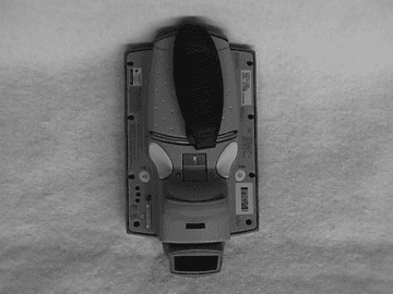
Click to zoom
Application Details
- Equipment Class
- DSS - Part 15 Spread Spectrum Transmitter
- Date of Grant
- May 04, 2000
- Application Purpose
- Original Equipment
- Date of Application
- Feb 29, 2000
- Frequency Range
- 2414.00000000 - 2462.00000000
- Company
- Symbol Technologies Inc
- Country
- United States
Documents & Files
Document Text
Text extracted from the exhibit documents filed with the FCC. Open a document above to read the original.
Users Manual
The following regulatory information will be added to the final version of the User’s manual. Regulatory Addendum Radio Frequency Interference Requirements This device has been tested and found to comply with the limits for a Class A digital device pursuant to Part 15 of the Federal Communications Rules and Regulation. These limits are designed to provide reasonable protection against harmful interference when the equipment is operated in a commercial environment. This equipment generates, uses, and can radiate radio frequency energy and, if not installed and used in accordance with the instruction manual, may cause harmful interference to radio communications. Operation of this equipment in a residential is likely to cause harmful interference in which case the user will be required to correct the interference at his own expense. However, there is no guarantee that interference will not occur in a particular installation. If the equipment does cause harmful interference to radio or television reception, which can be determined by turning the equipment off and on, the user is encouraged to try and correct the interference by one of the following measures: • Re-orient or relocate the receiving antenna. • Increase the separation between the equipment and receiver. • Connect the equipment into an outlet on a circuit different from that which the receiver is connected. • Consult the dealer or an experienced radio/TV technician for help. This device complies with FCC Part 15. Operation is subject to the following two conditions: (1) this device may not cause harmful interference and (2) this device must accept any interference received, including interference that may cause undesired operation.” Radio Frequency Interference Requirements- Canada This device complies with RSS 210 of Industry & Science Canada. Operation is subject to the following two conditions: (1) this device may not cause harmful interference and (2) this device must accept any interference received, including interference that may cause undesired operation.” This Class A digital apparatus meets the requirements of the Industry Canada Standard ICES-003. Cet appareil numerique de la Classe A est conforme a la norme NMB-003 du Canada. CE Marking and European Union Compliance Products intended for sale within the European Union are marked with the CE Mark which indicates compliance to applicable Directives and European Normes (EN), as follows, Amendments to these Directives or ENs are included: Applicable Directives • Electromagnetic Compatibility Directive 89/336/EEC • Low Voltage Directive 73/23/EEC Applicable Standards • EN 55022-Limits and Methods of Measurement of Radio Interference Characteristics of Information technology Equipment • EN 55024:1998; Information technology equipment-Immunity characteristics-Limits and methods of measurement. • IEC 1000-4-2(1995-01)-Electromagnetic Compatibility (EMC) – Part 4: Testing and measurement techniques-Section 2: Electrostatic Discharge immunity test. • IEC 1000-4-3(1995-03)-Electromagnetic Compatibility (EMC) –Part 4: Testing and measurement techniques-Section 3: Radiated, radio-frequency electromagnetic field immunity test. • IEC 1000-4-4(1995-01)-Electromagnetic Compatibility (EMC) –Part 4: Testing and measurement techniques-Section 4: E lectrical Fast transient /burst immunity test. • EN 60 950+Amd1 + Amd @-Safety of Information Technology Equipment Including Electrical Business Equipment • EN 60 825-1 (EN 60 825)- Safety of Devices Containing Lasers Laser Devices Symbol products using lasers comply with US 21 CFR1040.10, Subchapter J and IEC 825/EN 60 825 (or IEC 825-1/EN 60 825-1, depending on the date of manufacture). The laser classification is marked on one of the labels on the product. Class 1 Laser devices are not considered hazardous when used for their intended purpose. The following statement is required to comply with US and international regulations: Caution: Use of controls, adjustments or performance of procedures other than those specified herein may result in hazardous laser light exposure. Class 2 laser scanners use a low power visible light diode. As with any very bright light source such as the sun, the user should avoid staring directly into the light beam. Momentary exposure to a Class 2 laser is not known to be harmful. RF Devices Symbol’s RF products are designed to be compliant with the rules and regulations in the locations into which they are sold and will be labeled as required. The majority of Symbol’s RF devices are type approved and do not require the user to obtain license or authorization before using the equipment. Any changes or modifications to Symbol Technologies equipment not expressly approved by Symbol Technologies could void the user’s authority to operate the equipment.
Users Manual
WaveLAN/IEEE Turbo 11 Mb PC Cardi You can find the most recent software and user documentation for all WaveLAN products on our internet site. If you encounter problems when installing or using this product, or would like information about our other WaveLAN products, please contact your local Authorized WaveLAN Reseller or regional Lucent Technologies Sales Office. You can find their address and phone numbers on the WaveLAN website. In case no local or regional support is available, you can reach us at the addresses or telephone numbers listed below. When contacting WaveLAN Support, please complete the WaveLAN Problem Report form and include it with your email or fax. The form (report.txt) is available on the WaveLAN Software CD-ROM, and on the WaveLAN Support pages of the WaveLAN website. Software and Documentation World Wide Webhttp://www.wavelan.com FTP Serverftp://ftp.wavelan.com/pub WaveLAN Regional Support U.S.A / [email protected] Caribbean/ Latin [email protected] Europe/ Middle-East/ [email protected] Asia/ [email protected] WaveLAN Global Support U.S.A / CanadaVoice:+1 800 WAVELAN-3 Caribbean/ Latin America Technical Support iiWaveLAN/IEEE Turbo 11 Mb PC Card Wireless Interoperability The IEEE 802.11 WaveLAN products are designed to be inter-operable with any wireless LAN product that is based on Direct Sequence Spread Spectrum (DSSS) radio technology, and is compliant to the IEEE 802.11 Standard on Wireless LANs (Revision B), as defined and approved by the Institute of Electrical and Electronics Engineers. WaveLAN and your Health WaveLAN, like other radio devices, emits radio frequency electromagnetic energy. The level of energy emitted by WaveLAN devices however is far much less than the electromagnetic energy emitted by wireless devices like for example mobile phones. Because WaveLAN operates within the guidelines found in radio frequency safety standards and recommendations, Lucent Technologies believes WaveLAN is safe for use by consumers. These standards and recommendations reflect the consensus of the scientific community and result from deliberations of panels and committees of scientists who continually review and interpret the extensive research literature. In some situations or environments, the use of WaveLAN may be restricted by the proprietor of the building or responsible representatives of the organization. These situations may for example include: •Using the WaveLAN equipment on board of airplanes, or •In any other environment where the risk of interference to other devices or services is perceived or identified as harmful. If you are uncertain of the policy that applies on the use of wireless devices in a specific organization or environment (e.g. airports), you are encouraged to ask for authorization to use the WaveLAN device prior to turning on the equipment. Information to the User WaveLAN/IEEE Turbo 11 Mb PC Cardiii The IEEE 802.11 WaveLAN PC Card must be installed and used in strict accordance with the manufacturer’s instructions. This device complies with the following radio frequency and safety standards. Canada - Industry Canada (IC) This device complies with RSS 210 of Industry Canada. Europe - EU Declaration of Conformity This device complies with the specifications listed below, following the provisions of the EMC Directive 89/336/EEC: •ETS 300-826 General EMC requirements for Radio equipment. •ETS 300-328 Technical requirements for Radio equipment. USA - Federal Communications Commission (FCC) This device complies with Part 15 of FCC Rules. Operation of the devices in a WaveLAN System is subject to the following two conditions: •This device may not cause harmful interference. •This device must accept any interference that may cause undesired operation. Exposure to Radio Frequency Radiation. Exposure to Radio Frequency Radiation. The radiated output power of the IEEE 802.11 WaveLAN PC Card is far below the FCC radio frequency exposure limits. Nevertheless, the WaveLAN PC Card shall be used in such a manner that the potential for human contact during normal operation is minimized. When using this device in combination with WaveLAN Outdoor Antenna products, a certain separation distance between antenna and nearby persons has to be kept to ensure RF exposure compliance. Refer to the Regulatory Statements as identified in the documentation that comes with those products for additional information. Regulatory Information Regulatory Information ivWaveLAN/IEEE Turbo 11 Mb PC Card Interference Statement This equipment has been tested and found to comply with the limits for a Class B digital device, pursuant to Part 15 of the FCC Rules. These limits are designed to provide reasonable protection against harmful interference in a residential installation. This equipment generates, uses, and can radiate radio frequency energy. If not installed and used in accordance with the instructions, it may cause harmful interference to radio communications. However, there is no guarantee that interference will not occur in a particular installation. If this equipment does cause harmful interference to radio or television reception, which can be determined by turning the equipment off and on, the user is encouraged to try and correct the interference by one or more of the following measures: •Reorient or relocate the receiving antenna. •Increase the distance between the equipment and the receiver. •Connect the equipment to an outlet on a circuit different from that to which the receiver is connected. •Consult the dealer or an experienced radio/TV technician for help. Lucent Technologies is not responsible for any radio or television interference caused by unauthorized modification of the devices included with this IEEE 802.11 WaveLAN Kit, or the substitution or attachment of connecting cables and equipment other than specified by Lucent Technologies. The correction of interference caused by such unauthorized modification, subs…
Text truncated - open the document above for the full version.
Attestation Statements
Sandy Mazzola Symbol Technologies, Inc. 1 Symbol Plaza Holtsville, N.Y. 11742 Voice : (516) 738-5373 Fax: (516) 738-3318 Letter of Confidentiality Request Dear Reviewer, Symbol Technologies (“Symbol”), requests that the Block Diagram, Schematics, and operational Description exhibits of the referenced application be withheld from routine availability for public inspection pursuant to Section 0.459 of the Commissions Rules an Freedom of Information Act (“FOIA) Exemption 4, 5 U.S.C. 552 (b) (4). These exhibits consist of “trade secrets (or) commercial or financial information obtained from a person and privileged or confidential” 5 U.S.C. 552 (b) (4), and is therefore entitled to protection from disclosure under FOIA. The documents in question contain trade secrets: detailed technical descriptions, specifications and schematics for a product to be offered for sale. These materials provide particulars on the product design. This information would give Symbol’s competitors an unearned and unwarranted competitive advantage. The documents contain “commercial information” within the scope of FOIA exemption 4. This information is the product of Symbol’s investment of money, personnel, and other resources. The result of the investment is a fairly earned position in the marketplace. Premature release of the information threatens substantial and unwarranted harm to Symbol’s competit ive posit ion. For these reasons, Symbol has taken pains to keep this technical information confidential, and intends to continue doing so. Symbol customarily witholds this information from persons outside the employ of Symbol and certain of its suppliers and contractors, and even within these groups routinely limits access to persons having a particular need for the information. If the Commissions were to make these documents public, it would be giving away hard won fruits of Symbols labors without compensation. The filing fee that is required for this confidentiality request is included in the check that accompanies this application. If there are any questions about this request, please call me at the number above. Thank you for your attention. Respectfully submitted, Sandy Mazzola
Cover Letter(s)
√ √√ √ Retlif Testing Laboratories 795 Marconi Avenue, Ronkonkoma, N.Y. 11779 (631) 737-1500 - FAX (631) 737-1497 (Branch Office) 101 New Boston Road, Goffstown, N.H. 03045 (603) 497-4600 - FAX (603) 497-5281 After electronically adding attachments for FCC ID H9PPPT4600SOHWEW9, Confirmation No. EA96908, I realized that I neglected to check the confidentiality boxes for the block diagrams and the operational description. ®
Cover Letter(s)
√ √√ √ Retlif Testing Laboratories 795 Marconi Avenue, Ronkonkoma, N.Y. 11779 (631) 737-1500 - FAX (631) 737-1497 (Branch Office) 101 New Boston Road, Goffstown, N.H. 03045 (603) 497-4600 - FAX (603) 497-5281 After electronically filing the 731 form for FCC ID H9PPPT4600SOHWEW9, Confirmation No. EA96908. I printed it out and saw that part of the frequency range was placed incorrectly in the “Rated RF power output”. The frequency range should be 2414 to 2462 MHz. ®
ID Label/Location Info
Sample FCC Label Symbol Technologies Inc. FCC ID: H9PPPT4600SOHWEW9 This device complies with Part 15 of the FCC rules. Operation is subject to the following two conditions: (1) this device may not cause harmful interference and (2) this device must accept any interference received, including interference that may cause undesired operation. This is a sample draft of the label that will be located on the underside of the product. Sandy Mazzola
Internal Photos
Antenna Alone, Front Close Up Antenna Alone, Front Full View Antenna Alone, Rear Close Up Antenna Alone, Rear Full View
Parts List/Tune Up Info
The content of this document is "LUCENT TECHNOLOGIES’ intellectual property" and is the property of LUCENT TECHNOLOGIES. It is to be treated as strictly confidential and is not to be disclosed, reproduced or used, except as authorised in writing by LUCENT TECHNOLOGIES in connection with the manufacture, maintenance and use of the LUCENT TECHNOLOGIES equipment to which it pertains. Copyright © 1999 LUCENT TECHNOLOGIES . CHANGES:NEXT ASSY (A) New SHEET234567891011 12 13 14 15 SIZEA4A4 A4 A3 A3 REV.AAAAA ADR0367611/99 REVDR-NUMBERINIT.DATE LUCENT TECHNOLOGIES NEDERLAND B.V. / WCND DESIGNER:J WielsmaDATE:UNIT: WaveLAN/IEEE PC Card type 2 16 bit 3V/5V CCK INTEGRATED for OEM SUPSD.BY:SUPSDS:NAME: BOARD ASSY SHEET:1 OF 6SCALE: COMCODE:DOC. NO.: 012427 ITEMPART/DWG #REQ'DNAME AND DESCRIPTIONNOTES LUCENT TECHNOLOGIES NEDERLAND B.V. / WCND012427 UNIT: WaveLAN/IEEE PC Card type 2 16 bit 3V/5V CCK INTEGRATED for OEM SCALE:REV. A NAME : BOARD ASSY SHEET 2 OF 6 10000042RFCON_PCCARD, CONNJ4 J5 20000352B3629, AIC, SIEMENS, B39351B3629Z10U13 U14 30000381MIC2920A-3.3BS, AIC, MICREL, MIC2920A-3.3BSU205 40008453CAP, 10uF, MURATA, GRM230Y5V106Z10C7 C283 C284 50017482CAP, 1uF, MURATA, GRM40X5R105K10C3 C37 60017491CAP, 2.2uF, MURATA, GRM40Y5V225Z10C10 70019064IND, 10uH, MURATA, LQG21C100N00L201 L203 L204 L205 80020522RES, 1.00, KOA, RK73H1JT1R00FR314 R315 90022361RES, 82.5, KOA, RK73H1JT82R5FR225 100027372CAP, 22nF, MURATA, GRM39X7R223K25C5 C250 110027481CAP, 1uF, MURATA, GRM39Y5V105Z10C240 120028512IND, 1.8nH, COILCRAFT, 0603CS-1N8XKBCL209 L210 130028611IND, 39nH, COILCRAFT, 0603CS-39NXJBCL15 140028824IND, 12nH, TOKO, LL1608-FH12NJL5 L6 L8 L14 150028853IND, 22nH, TOKO, LL1608-FH22NJL4 L10 L11 160028861IND, 27nH, TOKO, LL1608-FH27NJL18 170028872IND, 33nH, TOKO, LL1608-FH33NJL206 L207 180028891IND, 47nH, TOKO, LL1608-FH47NJL17 190028911IND, 68nH, TOKO, LL1608-FH68NJL208 200028931IND, 100nH, TOKO, LL1608-FHR10JL1 210032443RES, 100, KOA, RK73H1ETP1000FR234 R240 R312 220032831RES, 255, KOA, RK73H1ETP2550FR303 230032902RES, 301, KOA, RK73H1ETP3010FR29 R31 240032961RES, 348, KOA, RK73H1ETP3480FR305 250033024RES, 402, KOA, RK73H1ETP4020FR212 R213 R220 R221 260033112RES, 499, KOA, RK73H1ETP4990FR210 R238 270033192RES, 604, KOA, RK73H1ETP6040FR313 R320 280033342RES, 866, KOA, RK73H1ETP8660FR211 R214 290033408RES, 1.00k, KOA, RK73H1ETP1001FR19 R22 R23 R30 R32 R40 R235 R323 300033461RES, 1.15k, KOA, RK73H1ETP1151FR231 310033574RES, 1.50k, KOA, RK73H1ETP1501FR13 R25 R239 R242 320033698RES, 2.00k, KOA, RK73H1ETP2001FR18 R26 R27 R28 R206 R208 R237 R245 330033961RES, 3.83k, KOA, RK73H1ETP3831FR249 340034021RES, 4.42k, KOA, RK73H1ETP4421FR1 350034051RES, 4.75k, KOA, RK73H1ETP4751FR228 360034121RES, 5.62k, KOA, RK73H1ETP5621FR250 3700343611 RES, 10.0k, KOA, RK73H1ETP1002FR216 R224 R227 R232 R236 R241 R254 R256 R307 R308 R310 380034531RES, 15.0k, KOA, RK73H1ETP1502FR244 390034658RES, 20.0k, KOA, RK73H1ETP2002FR33 R200 R202 R215 R263 R264 R265 R272 400034859RES, 32.4k, KOA, RK73H1ETP3242FR2 R3 R4 R205 R207 R218 R226 R252 R306 410034931RES, 39.2k, KOA, RK73H1ETP3922FR233 420034962RES, 42.2k, KOA, RK73H1ETP4222FR5 R6 430035325RES, 100k, KOA, RK73H1ETP1003FR15 R203 R209 R217 R324 440036535CAP, 1.0pF, MURATA, GRM36COG1R0C50C9 C12 C23 C57 C271 450036585CAP, 2.2pF, MURATA, GRM36COG2R2C50C43 C44 C49 C64 C270 ITEMPART/DWG #REQ'DNAME AND DESCRIPTIONNOTES LUCENT TECHNOLOGIES NEDERLAND B.V. / WCND012427 UNIT: WaveLAN/IEEE PC Card type 2 16 bit 3V/5V CCK INTEGRATED for OEM SCALE:REV. A NAME : BOARD ASSY SHEET 3 OF 6 460036592CAP, 2.7pF, MURATA, GRM36COG2R7C50C233 C235 470036623CAP, 3.9pF, MURATA, GRM36COG3R9C50C26 C61 C263 480036713CAP, 8.2pF, MURATA, GRM36COG8R2C50C17 C35 C245 490036733CAP, 10pF, MURATA, GRM36COG100C50C48 C66 C269 5000367520 CAP, 12pF, MURATA, GRM36COG120J50C16 C21 C22 C24 C28 C29 C32 C38 C45 C50 C51 C59 C215 C216 C238 C241 C242 C246 C256 C279 5100368117 CAP, 22pF, MURATA, GRM36COG220J50C41 C42 C46 C47 C52 C58 C247 C248 C249 C251 C252 C259 C261 C262 C264 C265 C266 520036832CAP, 27pF, MURATA, GRM36COG270J50C204 C208 530036892CAP, 47pF, MURATA, GRM36COG470J50C30 C34 540036998CAP, 120pF, MURATA, GRM36COG121J50C56 C207 C232 C234 C237 C253 C254 C257 5500371415 CAP, 1nF, MURATA, GRM36X7R102K50C18 C20 C65 C200 C202 C205 C206 C210 C212 C217 C219 C228 C229 C260 C278 560037151CAP, 1.2nF, MURATA, GRM36X7R122K50C255 570037191CAP, 2.7nF, MURATA, GRM36X7R272K50C53 580037211CAP, 3.9nF, MURATA, GRM36X7R392K50C2 590037261CAP, 10nF, MURATA, GRM36X7R103K16C277 600037273CAP, 15nF, MURATA, GRM36Y5V153Z50C201 C222 C224 6100373130 CAP, 100nF, MURATA, GRM36Y5V104Z16C4 C19 C25 C36 C54 C55 C60 C62 C203 C209 C211 C214 C218 C220 C223 C227 C230 C231 C236 C239 C244 C258 C267 C272 C273 C274 C275 C280 C281 C282 620038561IND, 2.7nH, TOKO, LL1005-FH2N7SL13 630038591IND, 4.7nH, TOKO, LL1005-FH4N7KL211 640038662IND, 18nH, TOKO, LL1005-FH18NKL12 L16 6500505112 RES, 0, KOA, RM73Z1ETDR8 R38 R99 R230 R253 R257 R268 R269 R273 R311 R316 R317 660050765RES, 10, KOA, RM73B1ETP10RJR9 R35 R219 R309 R318 670050832RES, 20, KOA, RM73B1ETP20RJR222 R223 680050932RES, 51, KOA, RM73B1ETP51RJR243 R302 690051071RES, 200k, KOA, RM73B1ETP2003JR16 700051251RES, 1.0, KOA, RK73H2A1R0FR11 710051391RES, 3.9, KOA, RK73H2A3R9FR10 720100011SA2420, AIC, PHILIPS, SA2420U204 730100021SA1630B, AIC, PHILIPS, SA1630BU201 740100032BFP420, TRANSISTOR, SIEMENS, Q62702-F1591Q3 Q207 75010004_1MA-LC22.000MHz, AIC, USI, MA-LC22.000MHzU8 760100051SI2301DS, TRANSISTOR, SILICONIX, (TEMIC)Q1 770100061MQE901_704, AIC, MURATA, MQE901-704U6 780100091BFP450, TRANSISTOR, SIEMENS, Q62702-F1590Q4 ITEMPART/DWG #REQ'DNAME AND DESCRIPTIONNOTES LUCENT TECHNOLOGIES NEDERLAND B.V. / WCND012427 UNIT: WaveLAN/IEEE PC Card type 2 16 bit 3V/5V CCK INTEGRATED for OEM SCALE:REV. A NAME : BOARD ASSY SHEET 4 OF 6 790100113BC847BW, TRANSISTOR, PHILIPS, BC847BWQ200 Q201 Q206 800100121BC857BW, TRANSISTOR, PHILIPS, BC857BWQ205 810100141CON_68_POLIG, CONN, PCMCIA_ITT, 1215820032J3 820100151UMA1021M, AIC, PHILIPS, UMA1021MU203 830…
Text truncated - open the document above for the full version.
RF Exposure Info
15.247(b)(4) The device does not operate in such a manner that causes the public to be exposed to levels in excess of the commissions guidelines. The devices maximum output power at the antenna terminal is 34.7mWatts, as measured by a peak power meter. The patch antenna used in the device has a maximum gain of 0dBi in all directions (See file Antinfo.pdf contained in the operational description exhibit for Spec sheet). The device may operate within 20cm of a user and does not exceed the MPE as outlined in OET Bulletin 65, Supplement C, therefore, SAR evaluation is deemed unnecessary.
Test Report
Nederland B.V. WCND FCC ID: WLPC24H/WLPCE24H Report No. 011734, Rev. B TEST REPORT Subject: Processing Gain For WaveLAN IEEE PC CARD type 2 HS Ref.: FCC Rules 47 CFR Part 15, Section 5.247d Report Prepared by: Maarten Visee May 6, 1999 Name Signature Date Concurrence: 1. Director of Engineering Bruce Tuch May 6, 1999 Name Signature Date 2. Team Captain Frans Hoekstra May 6, 1999 Name Signature Date FCC Processing Gain Measurements Results, FCCID WLPC24H/WLPCE24H, Report No. 011734, Rev. B. Lucent WCND Confidential ©1999 2 Lucent WCND Confidential Information ©1999 FCC Processing Gain Measurements Results, FCCID WLPC24H/WLPCE24H, Report No. 011734, Rev. B. Lucent WCND Confidential ©1999 i Date Section Description 04/16/99, Rev. A Initial release. 05/6/99, Rev. B 2 Changed spreading gain into processing gain. 4.1 For data rates of 5.5 and 11 Mbit/s changed processing gain requirements of 9 dB into 10 dB. 4.2 Changed description for demodulated data availability at the interconnection between RF and DSP into the interconnection between DSP and digital circuits. Changed spreading gain into processing gain. 7.2, 7.3 Changed sub sections Measurement Results and Measurement Conclusion. Annex A Updated flow chart. Change History: FCC Processing Gain Measurements Results, FCCID WLPC24H/WLPCE24H, Report No. 011734, Rev. B. Lucent WCND Confidential ©1999 1 This document describes the Receiver Processing Gain verification measurements performed at the WaveLAN-II PC-Card Type 2, according to Ref.[2]. The Lucent WaveLAN-II PC-Card Type 2 product confirms to the minimum required 10 dB processing gain, as set forth by the FCC for operation in the 2.4 GHz ISM band. 1- Document FCC 97-114, Appendix C, Guidance on Measurements for Direct Sequence Spread Spectrum Systems. 2- Hardware Functional Specification for WaveLAN-II Embedded, High Speed, Doc. No. 011735, Rev. A, Source Organization Lucent Technologies WCND Utrecht. 3- Viterbi, A. J., Principles of Coherent Communications, New York, McGraw-Hill 1966. 4- Proakis, J.G., Digital Communications, New York, McGraw-Hill 1989, page 270. 4.1 Test introduction - FCC requirements: Part of FCC certification for the Lucent WaveLAN IEEE 802.11 High Speed compliant Network Interface Card (NIC) is a processing gain test. This test proves that the receiver of the tested product employs a true spread spectrum device receiver structure, taking full advantage of the direct sequence spread spectrum modulation technique. This test verifies the receiver processing gain to be 10 dB or more for a data rate of 1, 2, 5.5 and 11 Mbit/s, by monitoring the Bit Error Rate (BER) of the product under test for each data rate, while operating under strict defined received signal conditions. Several methods of showing compliance to the rules are possible, from a stepped CW jammer to a continuous sweeping CW interferer. For this test the discrete stepped CW jammer method was chosen, as described in Ref.[1]. 1.Summary: 2.Conclusion: 3.References: 4.Measurement description: FCC Processing Gain Measurements Results, FCCID WLPC24H/WLPCE24H, Report No. 011734, Rev. B. Lucent WCND Confidential ©1999 2 Therefore a receiver input signal is applied to the product under test, in the presence of a Continuous Wave (CW) interference source, also referred to as CW jammer. The test takes place at the product Functional Specification (Ref.[2]) specified conditions for BER rate measurements, specifying a BER equal or better than 10^-8 at a receiver input level of -55 dBm. For practical reasons these test are performed at -55 dBm or -53 dBm. This small deviation from the Functional Specification should not cause any deviation from the specified Bit Error Rate, since the received levels are well above the thermal noise. The test criteria for meeting the minimal processing gain is such that it takes the theoretical calculated SNR for the applied modulation technique and specified BER as a reference. From this given SNR the processing gain is subtracted, yielding the CW Jammer to Signal ratio J/S. From Ref. [4], likewise as Ref.[3] consulted in Ref. [1], it is determined that for a BER of 10^-8 the SNR (S/N)o equals: 13 dB @ 1 Mbit/s, 15 dB @ 2 Mbit/s, 15 dB @ 5.5 Mbit/s, 18 dB @ 11 Mbit/s. Thus the J/S ratio for a processing gain of 10 dB that must be met is calculated as: -13 + 10 = -3 dB @ 1 Mbit/s (DBPSK), -15 + 10 = -5 dB @ 2 Mbit/s (DQPSK), -15 + 10 = -5 dB @ 5.5 Mbit/s (CCK), -18 + 10 = -8 dB @ 11 Mbit/s (CCK). Two types of measurement corrections are allowed for as described in Ref.[1]. The first taking into account 2 dB implementation losses, thus increasing the absolute J/S ratio by 2 dB. The second correction allows for deleting the 20% worst- case frequencies in the processing gain test that causes the test at that CW interference to fail. This implies that for the considered 14 MHz wide measurement interval the worst case 57 CW jammer frequencies can be ignored, being those that result in FCC Processing Gain Measurements Results, FCCID WLPC24H/WLPCE24H, Report No. 011734, Rev. B. Lucent WCND Confidential ©1999 3 received data errors/missing frames (20% of 14 MHz *(1 MHz/50 KHz) + 1 = (20% * 281) + 1 = 57). FCC Processing Gain Measurements Results, FCCID WLPC24H/WLPCE24H, Report No. 011734, Rev. B. Lucent WCND Confidential ©1999 4 4.2 Test sequence: The measurements are performed at a 50 KHz CW jammer raster. For each CW jammer frequency 10^8 bits are transmitted by the reference transmitter, and received by the product under test. For practical reasons 50.000 messages are transmitted. After blanking out frame overhead 1927 bits per frame are monitored. This results in 50.000 * 1927 = 9650000 transmitted bits for a BER test, which is a mere 1.4% less than the targeted 10^8 bits. Though it would be more elegant to show BER compliance for at least say ten times 10^8 transmitted/received bits, the time involved with this grows significantly. Since the CW interferer is stepped in a 50 KHz raster, cov…
Text truncated - open the document above for the full version.
Test Report
Test Report Number R-8392-1 APPLICANT Symbol Technologies Inc One Symbol Plaza Holtsville, NY 11742 MANUFACTURER Lucent Technologies TEST SPECIFICATION:FCC Rules and Regulations Part 15, Subpart C TEST PROCEDURE:ANSI C63.4:1992 TEST SAMP LE DESCRIP TION BRANDNAME:Symbol MODEL:PPT4600 FCC ID:H9PPPT4600SOHWEW9 TYPE:2.4 GHz Direct Sequence Spread Spectrum Transceiver FREQUENCY RANGE:2412 to 2462 MHz POWER REQUIREMENTS: Internal Nicad Batteries or 11 VDC derived from Symbol AC Adapter, P/N: 50-14000-045 TESTS P ERFORMED - 15.207(a)Conducted Emissions, AC Power - 15.247(a)(2)Occupied Bandwidth - 15.247(b)(1)Power Output - 15.247(c)Spurious Emissions, Antenna Conducted Emissions, Forbidden Band Radiated Emissions - 15.247(c)Radiated Emissions, Transit Mode - 15.247(d)Power Density - 15.247(e)Processing Gain Data Test Report Number R-8392-1 REPORT OF MEASUREMENTS Applicant:Symbol Technologies, Inc. Device:2.4 GHz Direct Sequence Spread Spectrum Transceiver FCC ID:H9PPPT4600SOHWEW9 Power Requirements:Internal Nicad Batteries or 11 VDC derived from Symbol AC Adapter, P/N: 50-14000-045 Applicable Rule Section:Part 15, Subpart C, Section 15.247 TEST RESULTS 15.207(a):The radio frequency voltage that was conducted back on to the AC power line on any frequency/frequencies within the bandwidth of 450kHz to 30MHz did not exceed 250 microvolts. 15.247(a)(2): The minimum 6dB bandwidth was no less than 500 kHz. 15.247(b)(1): The maximum peak output power of the transmitter did not exceed 1 watt. The test sample=s peak power measured 29.5mW. 15.247(b)(4) The device does not operate in such a manner that causes the public to be exposed to levels in excess of the commissions guidelines. The devices maximum output power at the antenna terminal is 29.5mW. The patch antenna used in the device has a maximum gain of 0dBi in all directions. The device may operate within 20cm of a user and does not exceed the MPE as outlined in OET Bulletin 65, Supplement C, therefore, SAR evaluation is deemed unnecessary. 15.247(c):The antenna conducted emissions were found to be at least 20dB down from the fundamental frequencies. All other emissions outside these bands did not exceed the general radiated emissions limits specified in 15.209(a). 15.247(d):The power density did not exceed 8dBm in any 3 kHz bandwidth averaged over 1 second. 15.247(e)The process gain information was supplied by Symbol and can be found as a separate e-file attachment named Lucent Processing Gain.doc. Test Report Number R-8392-1 GENERAL NOTES 1.All readings were taken using a peak detector function at a distance of 3 meters. 2. The duty cycle was applied to the peak readings in order to determine the average value of emissions. 3.All measurements were made with the device operating on the AC Power Adapter, Symbol P/N: 50-14000-045. 4. The frequency range was scanned form 30 MHz to 25 GHz. All emissions not reported were more than 10dB below the specified limit. Tes…
Text truncated - open the document above for the full version.
Contact Information
Applicant
Qianlin Zhou(Regulatory Specialist)
Technical Contact
Retlif Testing LaboratoriesThomas J Schneider
[email protected]631-737-1500
795 Marconi Avenue · Ronkonkoma, New York · United States
Non-Technical Contact
Retlif Testing LaboratoriesMichelle Tirado
[email protected]631-737-1500
Technical Specifications
| # | Rule Parts | Frequency Range | Power Output |
|---|---|---|---|
| 1 | 15C | 2.41 GHz - 2.46 GHz | 34.70 mW |
Other Applications from Symbol Technologies Inc

H9PCCHUB1
Jun 30, 2015Customer Concierge
Equipment Class
NII - Unlicensed National Information Infrastructure TX
H9PAP7562
May 10, 2015802.11 abgn/ac Access Point
Equipment Class
DTS - Digital Transmission System
H9PTC75AH
Mar 26, 2015Touch Computer
Equipment Class
NII - Unlicensed National Information Infrastructure TX
H9PRA1202
Sep 24, 2014UHF Narrowband Radio Module
Equipment Class
TNB - Licensed Non-Broadcast Station Transmitter
H9PEMG101
Aug 26, 2014802.15.4 Gateway
Equipment Class
DTS - Digital Transmission System