H9PRF1224Multi-protocol UHF RFID reader
Symbol Technologies Inc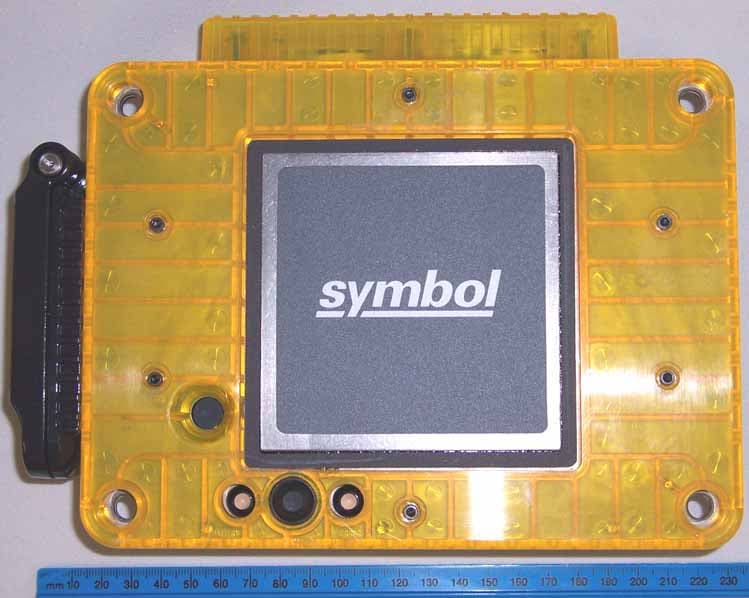
Click to zoom
Application Details
- Equipment Class
- DSS - Part 15 Spread Spectrum Transmitter
- Date of Grant
- Jul 30, 2006
- Application Purpose
- Original Equipment
- Date of Application
- Jul 17, 2006
- Equipment Note
- Multi-protocol UHF RFID reader
- Frequency Range
- 902.91000000 - 927.29000000
- Company
- Symbol Technologies Inc
- Country
- United States
Documents & Files
Document Text
Text extracted from the exhibit documents filed with the FCC. Open a document above to read the original.
Users Manual
LEDs / Ports © 2006 SYMBOL TECHNOLOGIES, INC. All rights reserved. Symbol reserves the right to make changes to any product to improve reliability, function, or design. Symbol does not assume any product liability arising out of, or in connection with, the application or use of any product, circuit, or application described herein. No license is granted, either expressly or by implication, estoppel, or otherwise under any patent right or patent, covering or relating to any combination, system, apparatus, machine, material, method, or process in which Symbol products might be used. An implied license exists only for equipment, circuits, and subsystems contained in Symbol products. Symbol and the Symbol logo are registered trademarks of Symbol Technologies, Inc. Other product names mentioned in this manual may be trademarks or registered trademarks of their respective companies and are hereby acknowledged. Symbol Technologies, Inc. One Symbol Plaza Holtsville, N.Y. 11742-1300 http://www.symbol.com Reference Documents Supporting documents, including the latest version of this guide are available for viewing/download from the Symbol documentation web site: http://www.symbol.com/manuals Software updates, SDKs, development support and related documents are available from the Symbol Devzone web site: http://devzone.symbol.com Patents This product is covered by one or more of the patents listed on the web site: http://www.symbol.com/patents Warranty For the complete Symbol hardware product warranty statement, go to: http://www.symbol.com/warranty Service Information Contact information is provided on the Symbol contact web site: http://www.symbol.com/contactsupport LED / PortsDescription Battery LEDGreen - Battery charge is good Flash Red - Battery needs charging. Amber Flash - Battery is charging Solid Amber - Battery is fully charged Error LEDFlash Red - Error, replace unit. External Antenna PortRF1000-FL - Supports up to one external antenna. USB Client PortUSB client connection. External Power PortSee Power Supply for the Symbol approved power supply information. USB Client Port External Power Port External Antenna Port Mounting Holes (4) Battery Door Power Button Error LED Physical Connections Battery LED 72-XXXXX-01 Revision A — July 2006 RF1000-FL Quick Reference Quide Microsoft ® CE .NET 5.0 Introduction This Quick Reference Guide (QRG) provides the required information for all product models in the RF1XXX Series of RFID readers. The user documents use the RF1000-FL model number to generically reference all of the RFID readers in the series. The QRG includes LED definitions, port descriptions, and mounting information. For details, refer to the RF1000-FL Integrator Guide P/N 72E-XXXXX-XX, available at: http://www.symbol.com/manuals Product Description The RF1000-FL is an intelligent, multi-protocol UHF RFID reader with RFID read performance that provides real-time, seamless EPC-compliant tags processing. Features: •UHF Generation 2 support •EPC Class 0 and Class 1 •Intel XScale ® processor with Windows ® CE •Support for custom or third-party applications •Feature set for event and tag management. Firmware Updates The RF1000-FL is shipped with the current firmware version. To install the latest upgrade refer to the RF1000-FL Integrator Guide P/N 72E-XXXXX-XX, available from: http://www.symbol.com/manuals Installation/Mounting For details on the required procedures and detailed installation instructions refer to the RF1000-FL Integrator Guide P/N 72E- XXXXX-XX, available from: http://www.symbol.com/manuals Prior to installation/mounting the following procedures must be performed: •The mounting brackets (or mounting platform) must be secured. •The LAN administrator must configure the RF1000-FL to communicate with the local LAN network and must set up the application interface software for the local LAN environment. •The battery must be fully charged. Mounting 1.Insert the rubber shock mounts into the mounting holes. 2.Position the RF1000-FL on the mounting brackets (or mounting platform). Ensure the clearance on all sides. 3.Insert the mounting bolts through the rubber shock mounts and through the bracket holes. 4.Attach the nuts onto the mounting bolts and tighten to 2.8 ft.-lbs to secure the RF1000-FL to the mounting brackets. Operation Press power button to toggle power on/off. The battery LED lights green to indicate the battery is good. If the Error LED flashes red, remove the unit and return to the network administrator. Regulatory Information All Symbol devices are designed to be compliant with rules and regulations in locations they are sold and will be labeled as required. If local language translations are available, they are provided at: http://www.symbol.com/services/manuals. Any changes or modifications to Symbol Technologies equipment, not expressly approved by Symbol Technologies, could void the user's authority to operate the equipment. Antennas: Use only the supplied or an approved replacement antenna. Unauthorized antennas, modifications, or attachments could cause damage and may violate regulations Caution: Only use Symbol approved and UL Listed accessories, battery packs and battery chargers. Do NOT attempt to charge damp/wet units or batteries. All components must be dry before connecting to an external power source. Products Equipped with Bluetooth® Wireless Technology This device can contain the following Bluetooth® qualified subsystems: • BTID: B01825 • BTID: B02413. Country Approvals Regulatory markings are applied to the device signifying country approvals, see notes 1 and 2 Please refer to the Symbol Declaration of Conformity (DoC) for details. This is available at http://www2.symbol.com/doc/. Note 1: The use of 5GHz RLAN's have varying restrictions of use; please refer to the Symbol Declaration of Conformity (DoC) for details. Note 2: The use of RFID Devices have varying restrictions of use; please refer to the Symbol Declaration of Conformity (DoC) for details. …
Text truncated - open the document above for the full version.
Cover Letter(s)
One Symbol Plaza, Holtsville, NY 11742-1300 • 1.631.738.2400 • www.symbol.com Confidentiality Request: Symbol Technologies June 16th 2006 Federal Communications Commission Authorization and Evaluation Division FCC ID: H9PRF1224 Pursuant to Sections 0.457 and 0.459 of the Commission’s Rules, the Applicant hereby requests confidential treatment of information accompanying this Application as outlined below: • Bill of Materials • Block Diagram • Schematics • Theory of Operation The above materials contain trade secrets and proprietary information not customarily released to the public. The public disclosure of these matters might be harmful to the Applicant and provide unjustified benefits to its competitors. The Applicant understands that pursuant to Rule 0.457, disclosure of this Application and all accompanying documentation will not be made before the date of the Grant for this application Sincerely yours, Alan Parrish Director, Regulatory Symbol Technologies Inc. 1 Symbol Plaza Holtsville, NY 11742
Cover Letter(s)
American Telecommunications Certification Body Inc. 6731 Whittier Ave, McLean, VA 22101 July 5, 2006 RE: FCC ID: H9PRF1224_ATCB003685 Attention: Gregory M. Snyder / Brian J. Dettling I have a few comments on this Application. Please note that further comments may arise in response to answers provided to the questions below. 1. Please note that the application indicates that this device is intended for use in “hand held computers”. This indicates the use of this device in a host that may be worn on the Body, yet no SAR testing was done in any host. Please explain how this device is used in a hand held computer and how that hand held computer cannot be worn on the body thus not requiring SAR testing. If the device is to be used in a host that can be worn on the body, please identify these type devices and provide SAR data in each type hand held computer in which the device would be used. 2. Please note that the manual states that a ‘stand alone’ external antenna configuration exists where a 25cm separation distance must be maintained. The manual also states the device is compliant to SAR requirements (indicating portable use). Please correct the manual as needed and please be consistent on the rf exposure configurations associated with this device. 3. Please note that the manual states that firmware can be updated. Please also note that the manual states that correct frequency operation in the associated countries is controlled by firmware. Please confirm that a US user cannot download or update firmware in the US that will allow the device to operate on non-US frequencies. 4. Please note that the MPE report and EMC report indicates simultaneous transmission on all bands. However, it is not clear from the manual or operational description if simultaneous transmission on different frequency bands is possible in this device. Please confirm if simultaneous transmission is an appropriate mode for this device. 5. Is this a modular approval or a Limited Modular Approval? If so, please provide a letter stating how the device complies with the modular approval requirements of D001407. 6. Please note that while the reports state that ANSI C63.4 was used as the test method, spread spectrum devices under 15.247 and UNII devices under 15.407 do not use ANSI C63.4 except in setup configurations. This type device uses specific test procedures established by the FCC. Please confirm that the appropriate approved test method was used to test this device. 7. Please note that the MPE data in the EMC report (pages 28 through 30 and 56 through 58) are not correct. The separate MPE report however, does have the correct information. Please either correct the MPE pages 28 through 30 and 56 through 58 of the EMC report or please remove this incorrect section. 8. Please provide a pseudo-random hopping list of the 902-928 FHSS device. 9. Please note that the 802.11a data provide in report “RF1224 Test Report - 802.11a.pdf” is almost 2 years old and is for a different FCC ID number. The FCC has stated that while they will accept data up to a year old, they will not accept data more than one year old. Please provide test data that is within the allowable time limit and please provide the relevance of test data not specifically issued for this device. Dennis Ward mailto:[email protected] The items indicated above must be submitted before processing can continue on the above referenced application. Failure to provide the requested information may result in application termination. z Page 2 July 5, 2006 Correspondence should be considered part of the permanent submission and may be viewed from the Internet after a Grant of Equipment Authorization is issued. Please do not respond to this correspondence using the email reply button. In order for your response to be processed expeditiously, you must submit your documents through the AmericanTCB.com website. Also, please note that partial responses increase processing time and should not be submitted. Any questions about the content of this correspondence should be directed to the sender.
Cover Letter(s)
Response to ATCB Comments FCC ID: H9PRF1224 1 Washington Laboratories, Ltd. 7560 LINDBERGH DRIVE GAITHERSBURG, MD 20879 (301) 417 – 0220 FAX # (301) 417 - 9069 July 17, 2006 Mr. Dennis Ward American Telecommunications Certification Body Inc. 6731 Whittier Ave McLean, VA 22101 RE: Comments of July 5, 2006 APPLICATION: H9PRF1224 Symbol Technologies, Inc. Dear Mr. Ward: Below are the comments that you have provided regarding the application for certification referenced above. Our responses to those comments are in bold italic. Many responses refer you to additional exhibit(s) which has been uploaded to the application folder at the ATCB website. Thank you for your attention. Please feel free to contact us for any additional information that you may require. Regards, Gregory M. Snyder Chief EMC Engineer, Wireless/Telco Services Manager Brian J. Dettling Documentation Specialist WLL Project: 9197 1) Please note that the application indicates that this device is intended for use in “hand held computers”. This indicates the use of this device in a host that may be worn on the Body, yet no SAR testing was done in any host. Please explain how this device is used in a hand held computer and how that hand held computer cannot be worn on the body thus not requiring SAR testing. If the device is to be used in a host that can be worn on the body, please identify these type devices and provide SAR data in each type hand held computer in which the device would be used. R. The RF1224 APEX unit is a finished system containing an RFID module, WLAN card, and Bluetooth module for mounting on a forklift. There is no hand-held or body worn configuration. 2) Please note that the manual states that a ‘stand alone’ external antenna configuration exists where a 25cm separation distance must be maintained. The manual also states the device is compliant to SAR Response to ATCB Comments FCC ID: H9PRF1224 2 requirements (indicating portable use). Please correct the manual as needed and please be consistent on the rf exposure configurations associated with this device. R. The manual has been corrected. Please see exhibit “RF1224 User Manual Rev 2”. 3) Please note that the manual states that firmware can be updated. Please also note that the manual states that correct frequency operation in the associated countries is controlled by firmware. Please confirm that a US user cannot download or update firmware in the US that will allow the device to operate on non-US frequencies. R. The firmware is factory set and cannot be changed by the end user to operate on non-US frequencies. 4) Please note that the MPE report and EMC report indicates simultaneous transmission on all bands. However, it is not clear from the manual or operational description if simultaneous transmission on different frequency bands is possible in this device. Please confirm if simultaneous transmission is an appropriate mode for this device. R. The unit will support simultaneous transmissions for the WLAN, Bluetooth and RFID. Section 7 of the APEX Pt2. Test Report discusses the collocation testing performed. 5) Is this a modular approval or a Limited Modular Approval? If so, please provide a letter stating how the device complies with the modular approval requirements of D001407. R. This is not a modular approval. Some of the devices contained in the unit (WLAN and RFID) have been approved as modules. 6) Please note that while the reports state that ANSI C63.4 was used as the test method, spread spectrum devices under 15.247 and UNII devices under 15.407 do not use ANSI C63.4 except in setup configurations. This type device uses specific test procedures established by the FCC. Please confirm that the appropriate approved test method was used to test this device. R. The appropriate procedures set out by the FCC were followed when testing the UNII and DTS parts of the APEX. 7) Please note that the MPE data in the EMC report (pages 28 through 30 and 56 through 58) are not correct. The separate MPE report however, does have the correct information. Please either correct the MPE pages 28 through 30 and 56 through 58 of the EMC report or please remove this incorrect section. R. The MPE data in the RFID EMC Report is not to be used with the RF1224 APEX approval. Only the conducted data at the antenna port is to be used for this application. The report was not altered as per the copyright information contained in the 8) Please provide a pseudo-random hopping list of the 902-928 FHSS device. R. Please see exhibit “WJ MPR7XXX Operational Desc- Freq Hop”. 9) Please note that the 802.11a data provide in report “RF1224 Test Report - 802.11a.pdf” is almost 2 years old and is for a different FCC ID number. The FCC has stated that while they will accept data up to a year old, they will not accept data more than one year old. Please provide test data that is within the allowable time limit and please provide the relevance of test data not specifically issued for this device. Response to ATCB Comments FCC ID: H9PRF1224 3 R. The 802.11a card is a Symbol manufactured card. No changes are made to the module other than a new antenna. The data for the existing module is still valid and new radiated emissions data with the new antenna has been provided.
ID Label/Location Info
PROD FAM: RF1224 DESCRIPTION: LBL:LCD, RF1224 (R) APEX CTRY CODE:US/CAN COUNTRY:US/CAN SN POOL: STANDARD LBL STOCK PN: 63-84786-01 SEE NOTE 2 LBL SCRIPT : XXXXX01X *SEE NOTE 1 CCG1: F501 E DR 69-X X X X X -01A S/N: XXXXXXXXXXX P/N: XXXXXXXXXXXXXXXX 11-16 V --- 2A SYMBOL TECHNOLOGIES INC., HOLTSVILLE N.Y. 1 1742 SEE NOTE 7 SEE NOTE 8 SEE NOTE 6 SEE NOTE 9 SEE NOTE 4 S/N: BAR CODE LISTED ACCESSORY I.T .E. 9B97 ® MADE IN XXXXXX XXXXXXXXXXXXXXXXXX MFD: XXXXXXX X XXXX FCC ID: H9PRF1224 IC: 1549D-RF1224 MODEL:RF1224 NOTES: UNLESS OTHERWISE SPECIFIED 1. SCRIPT FILE TO BE CREATED BY MANUFACTURING. SCRIPT FILE MUST MATCH THIS DOCUMENT EXACTLY AND HAVE SAME REVISION. 2. LABEL STOCK P/N IS SUBJECT TO CHANGE. CHECK BOM FOR ACTUAL P ART NUMBER. 3. IN ALL CASES "XXX......" REPRESENTS VARIABLE FIELDS IN SCRIPT FILE. ACTUAL NUMBER OF CHARACTERS IN SCRIPT FILE MAY V ARY. 4. SERIAL NUMBER MUST BE 4PT MINIMUM CHARACTER HEIGHT IN SCRIPT FILE. 5. PART NUMBER MAY OR MAY NOT HAVE DASH BEFORE COUNTRY CODE. SEE BOM FOR ACTUAL MODEL DESCRIPTION. 6. "MFD:" REPRESENTS MANUFACTURE DAY, MONTH, YEAR AND REVISION OF PART NUMBER(IE: 12SEP03 X) 7. COUNTRY OF ORIGIN REQUIRED 8. ADD VARIABLE FIELD FOR PLANT CODE 9. LEAVE SPACE FOR FUTURE VARIABLE FIELD THIS DEVICE COMPLIES WITH PART 15 OF THE FCC RULES. OPERATION IS SUBJECT TO THE FOLLOWING TWO CONDITIONS:(1) THIS DEVICE MAY NOT CAUSE HARMFUL INTERFERENCE AND (2) THIS DEVICE MUST ACCEPT ANY INTERFERENCE RECEIVED INCLUDING INTERFERENCE THAT MAY CAUSE UNDESIRED OPERATION. THIS CLASS B DIGITAL APPARATUS COMPLIES WITH CANADIAN ICES-003. CET APPAREIL NUMÉRIQUE DE LA CLASSE B EST CONFORME À LA NORME NMB-003 DU CANADA. SEE PRODUCT GUIDE FOR RADIO AND PATENT INFO. PRELIMINARY 5/31/06 Label Location
Internal Photos
FCC ID: H9P2121160 SYMBOL TECHNOLOGIES INC 802.11a/b/g RLAN Module 2004 Not to be reproduced without the permission of TÜV Product Service LtdPage 1 of 4 PHOTOGRAPHS OF EQUIPMENT Internal View 1 21-21160-01 FCC ID: H9P2121160 SYMBOL TECHNOLOGIES INC 802.11a/b/g RLAN Module 2004 Not to be reproduced without the permission of TÜV Product Service LtdPage 2 of 4 PHOTOGRAPHS OF EQUIPMENT Internal View 2 21-21160-01 FCC ID: H9P2121160 SYMBOL TECHNOLOGIES INC 802.11a/b/g RLAN Module 2004 Not to be reproduced without the permission of TÜV Product Service LtdPage 3 of 4 PHOTOGRAPHS OF EQUIPMENT Internal View 3 21-21160-02 FCC ID: H9P2121160 SYMBOL TECHNOLOGIES INC 802.11a/b/g RLAN Module 2004 Not to be reproduced without the permission of TÜV Product Service LtdPage 4 of 4 PHOTOGRAPHS OF EQUIPMENT Internal View 4 21-21160-02
Internal Photos
WJ Communications Inc. 1.0 Watt RFID Reader Internal Photographs
RF Exposure Info
Document PRX9176-MPE FCC ID: H9PRF1224 RF Exposure Test Report Washington Laboratories, Ltd June 2006 Maximum Permissible Exposure Evaluation for Symbol Technologies, Inc. RF1224 FCC ID: H9PRF1224 IC: 1549D-RF1224 June 21, 2006 WLL PROJECT #: 9197 This report may not be reproduced, except in full, without the prior written consent of Washington Laboratories, Ltd. RF Exposure Evaluation Document PRX9176-MPE FCC ID: H9PRF1224 RF Exposure Test Report Washington Laboratories, Ltd June 2006 1 Maximum Permissible Exposure Test Report for FCC ID: H9PRF1224 IC: 1549D-RF1224 1.0 Introduction This report has been prepared on behalf of SYMBOL TECHNOLOGIES, INC. RF1224. Transmitter to show compliance with the RF exposure requirements as defined in FCC §1.1307. This device will operate with three radio frequency transmitters operating under the requirements of Pat 15.247 and 15.407: • RFID, 902M – 928MHz • Bluetooth, 2.4GHz • WLAN: 2.4G and 5 GHz 1.1 Requirements Three different categories of transmitters are defined by the FCC in OET Bulletin 65. These categories are fixed installation, mobile, and portable and are defined as follows: Fixed Installations: fixed location means that the device, including its antenna, is physically secured at a permanent location and is not able to be easily moved to another location. Additionally, distance to humans from the antenna is maintained to at least 2 meters. Mobile Devices: a mobile device is defined as a transmitting device designed to be used in other than fixed locations and to be generally used in such a way that a separation distance of at least 20 centimeters is normally maintained between the transmitter's radiating structures and the body of the user or nearby persons. Transmitters designed to be used by consumers or workers that can be easily re-located, such as a wireless modem operating in a laptop computer, are considered mobile devices if they meet the 20 centimeter separation requirement. The FCC rules for evaluating mobile devices for RF compliance are found in 47 CFR §2.1091. Portable Devices: a portable device is defined as a transmitting device designed to be used so that the radiating structure(s) of the device is/are within 20 centimeters of the Document PRX9176-MPE FCC ID: H9PRF1224 RF Exposure Test Report Washington Laboratories, Ltd June 2006 2 body of the user. Portable device requirements are found in Section 2.1093 of the FCC's Rules (47 CFR§2.1093). The FCC also categorizes the use of the device as based upon the user’s awareness and ability to exercise control over his or her exposure. The two categories defined are Occupational/ Controlled Exposure and General Population/Uncontrolled Exposure. These two categories are defined as follows: Occupational/Controlled Exposure: In general, occupational/controlled exposure limits are applicable to situations in which persons are exposed as a consequence of their employment, who have been made fully aware of the potential for exposure and can exercise control over their exposure. This exposure category is also applicable when the exposure is of a transient nature due to incidental passage through a location where the exposure levels may be higher than the general population/uncontrolled limits, but the exposed person is fully aware of the potential for exposure and can exercise control over his or her exposure by leaving the area or by some other appropriate means. Awareness of the potential for RF exposure in a workplace or similar environment can be provided through specific training as part of a RF safety program. If appropriate, warning signs and labels can also be used to establish such awareness by providing prominent information on the risk of potential exposure and instructions on methods to minimize such exposure risks. General Population/Uncontrolled Exposure: The general population / uncontrolled exposure limits are applicable to situations in which the general public may be exposed or in which persons who are exposed as a consequence of their employment may not be made fully aware of the potential for exposure or cannot exercise control over their exposure. Members of the general public would come under this category when exposure is not employment-related; for example, in the case of a wireless transmitter that exposes persons in its vicinity. Warning labels placed on low-power consumer devices such as cellular telephones are not considered sufficient to allow the device to be considered under the occupational/controlled category, and the general population/uncontrolled exposure limits apply to these devices. The SYMBOL TECHNOLOGIES, INC. RF1224 is evaluated to the General Population/Uncontrolled Exposure limits. 1.2 Radio Frequency Radiation Exposure Evaluation The MPE shall be calculated to show compliance with the power density limit for each radio and frequency individually at the minimum mounting distance. The total percentage of allowable RF Exposure will be calculated for each radio and then added to ensure the overall percentage does not exceed 100%. The following formula was used to calculate the Power Density fro each radio: Document PRX9176-MPE FCC ID: H9PRF1224 RF Exposure Test Report Washington Laboratories, Ltd June 2006 3 2 4R PG S π = Where: S = Power Density P = Output Power at the Antenna Terminals G = Gain of Transmit Antenna (linear gain) R = Distance from Transmitting Antenna For multiple transmitters, the powers are summed proportionate to the percentage of power from each transmitter compared to their respective limits. Transmitter Data: Transmitter Frequency System Description Power Output dBm Maximum Antenna Gain dB 902.7 MHz RFID 29.98 6 2.4 GHz Bluetooth 2.43 2 2.4 GHz 802.11b/g 19.4 -2.2 5 GHz 802.11a 18.95 -3.2 The following tables are the individual exposure calculations for each radio within the device. Document PRX9176-MPE FCC ID: H9PRF1224 RF Exposure Test Report Washington Laboratories, Ltd June 2006 4 RFID Radio: Tra nsmitte r #1 F…
Text truncated - open the document above for the full version.
Test Report
FCC ID: H9P2121160 Issued on Sep. 09, 2004 Report No.: F453101 SPORTON International Inc. TEL : 886-2-2696-2468 FAX : 886-2-2696-2255 FCC TEST REPORT CATEGORY : Module for Portable Host PRODUCT NAME : 802.11a/b/g RLAN module FCC ID. : H9P2121160 FILING TYPE : Certification – Class II Permissive Change BRAND NAME : SYMBOL TYPE NO. : 21-21160 MODEL OF HOST : MC3090 (with 11a/b/g module) APPLICANT : SYMBOL Technologies, Inc. One Symbol Plaza Holtsville, New York, 11742-1300 U.S.A MANUFACTURER : Universal Scientific Industrial Co., Ltd. 141, Lane 351, Taiping Road, Sec.1, Tsao Yuen, Nan-Tou, Taiwan, R.O.C. ISSUED BY : SPORTON INTERNATIONAL INC. 6F, No. 106, Sec. 1, Hsin Tai Wu Rd., His Chih, Taipei Hsien, Taiwan, R.O.C. Statements: This test report is only for the 802.11b/g part of the product, test result of 802.11a is in another separate test report. The test result in this report refers exclusively to the presented test model / sample. Without written approval of SPORTON, the test report shall not be reproduced except in full. Certificate or Test Report could not be used by the applicant to claim the product endorsement by CNLA, NVLAP or any agency of U.S. government. The test equipment used to perform the test are calibrated and traceable to NML/ROC or NIST/USA. Dr. Alan Lane Vice General Manager Sporton International Inc. Lab Code: 200079-0 FCC ID: H9P2121160 Issued on Sep. 09, 2004 Report No.: F453101 SPORTON International Inc. Page No. : i TEL : 886-2-2696-2468 Issued Date : Sep. 09, 2004 FAX : 886-2-2696-2255 Table of Contents History of this test report....................................................................................................................................ii 1. General Description of Equipment under Test.............................................................................................3 1.1. Applicant..........................................................................................................................................................................................3 1.2. Manufacturer ...................................................................................................................................................................................3 1.3. Basic Description of Equipment under Test ....................................................................................................................................3 1.4. Features of Equipment under Test..................................................................................................................................................3 1.5. Table for Carrier Frequencies .........................................................................................................................................................4 2. Test Configuration of the Equipment under Test.........................................................................................5 2.1. Description of the Test ....................................................................................................................................................................5 2.2. Frequency Range Investigated .......................................................................................................................................................5 2.3. Test Modes......................................................................................................................................................................................5 2.4. Description of Test Supporting Units...............................................................................................................................................6 2.5. Connection Diagram of Test System ..............................................................................................................................................6 2.6. Test Software ..................................................................................................................................................................................7 3. Test Location and Standards .........................................................................................................................8 3.1. Test Location...................................................................................................................................................................................8 3.2. Test Conditions ...............................................................................................................................................................................8 3.3. Standards for Methods of Measurement .........................................................................................................................................8 3.4. DoC Statement...............................................................................................................................................................…
Text truncated - open the document above for the full version.
Contact Information
Applicant
Qianlin Zhou(Regulatory Specialist)
Test Firm
Washington Laboratories, Ltd.Michael Violette
Technical Specifications
| # | Rule Parts | Frequency Range | Power Output |
|---|---|---|---|
| 2 | 15C | 902.91 MHz - 927.29 MHz | 955.00 mW |
Other Applications from Symbol Technologies Inc

H9PCCHUB1
Jun 30, 2015Customer Concierge
Equipment Class
NII - Unlicensed National Information Infrastructure TX
H9PAP7562
May 10, 2015802.11 abgn/ac Access Point
Equipment Class
DTS - Digital Transmission System
H9PTC75AH
Mar 26, 2015Touch Computer
Equipment Class
NII - Unlicensed National Information Infrastructure TX
H9PRA1202
Sep 24, 2014UHF Narrowband Radio Module
Equipment Class
TNB - Licensed Non-Broadcast Station Transmitter
H9PEMG101
Aug 26, 2014802.15.4 Gateway
Equipment Class
DTS - Digital Transmission System