H9PVC5090Vehicle Computer
Symbol Technologies Inc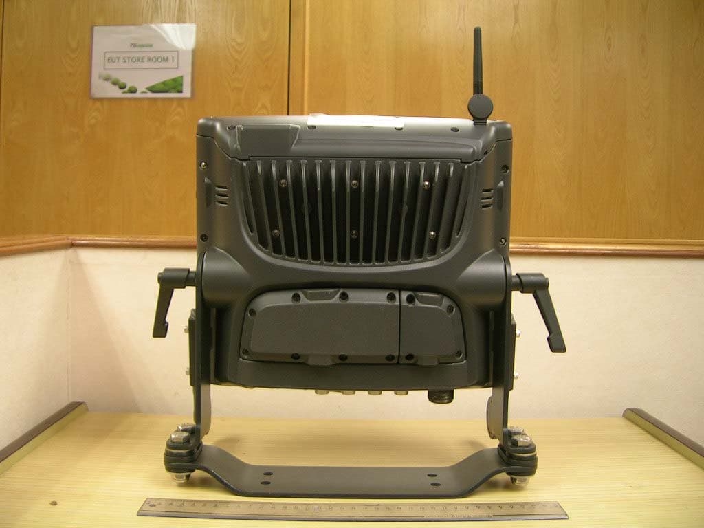
Click to zoom
Application Details
- Equipment Class
- DTS - Digital Transmission System
- Date of Grant
- Apr 11, 2006
- Application Purpose
- Original Equipment
- Date of Application
- Apr 11, 2006
- Equipment Note
- Vehicle Computer
- Frequency Range
- 5825.00000000 - 5830.00000000
- Company
- Symbol Technologies Inc
- Country
- United States
Documents & Files
Document Text
Text extracted from the exhibit documents filed with the FCC. Open a document above to read the original.
Users Manual
Quick Reference Guide VC5090 Vehicle Computer PRELIMINARY 2VC5090 Vehicle Computer © 2006 SYMBOL TECHNOLOGIES, INC. All rights reserved. Symbol reserves the right to make changes to any product to improve reliability, function, or design. Symbol does not assume any product liability arising out of, or in connection with, the application or use of any product, circuit, or application described herein. No license is granted, either expressly or by implication, estoppel, or otherwise under any patent right or patent, covering or relating to any combination, system, apparatus, machine, material, method, or process in which Symbol products might be used. An implied license exists only for equipment, circuits, and subsystems contained in Symbol products. Symbol and the Symbol logo are registered trademarks of Symbol Technologies, Inc. Other product names mentioned in this manual may be trademarks or registered trademarks of their respective companies and are hereby acknowledged. Symbol Technologies, Inc. One Symbol Plaza Holtsville, N.Y. 11742-1300 http://www.symbol.com Warranty Subject to the terms of Symbol’s hardware warranty statement, the VC5090 Vehicle Computer products are warranted against defects in workmanship and materials for a period of one year from the date of shipment. For the complete Symbol hardware product warranty statement, go to: http://www.symbol.com/warranty. Patents This product is covered by one or more patents. For patent information go to: http://www.symbol.com/patents . Quick Reference Guide3 Introduction The VC5090 Vehicle Computer is a vehicle or fixed-mount computer. The VC5090 has two configurations: a full-screen computer with optional keyboard and a half screen configuration with a built in keyboard. You can enter data using the touch screen, the keyboard, an optional bar code scanner, or a combination of the three. The data is transmitted wireless to a host computer. The vehicle computer features: • Ergonomic design with color LCD touch screen • Internal wide-range power supply (9 - 72 VDC) to accommodate propane, gasoline, and electric-powered forklifts • Internal antennas with external antenna port • Interfaces with scanners, printers, audio devices and other peripherals • Continuous operation at -30 °C (-22°F) (cold storage terminals) • Pre-loaded with terminal emulation software. About This Guide This guide contains the following: •Features on page 4 •Unpacking on page 5 •Optional Accessories on page 6 •Charging the Internal Backup Battery on page 20 •Calibrating the Touch Screen on page 21 •Resetting the Vehicle Computer on page 21 •Programmable Keys on page 22 •Connecting Accessories on page 22 •Maintenance on page 23 •Troubleshooting on page 24. For more information including installation instructions, refer to the VC5090 Product Reference Guide, p/n 72E-76347-xx available at http://www.symbol.com/manuals. 4VC5090 Vehicle Computer Features Optional Keyboard Angle Adjustment Knob Power LED Antenna Port for Optional External Antenna Display Built-In Keyboard Control Button Main Power Switch User Programmable Buttons Power Button Control LED WLAN COMM LED Mounting Bracket Quick Reference Guide5 Unpacking You should find the following items in the box: • VC5090 vehicle computer • mounting bracket • hardware bag • desiccant kit • three fuses and three fuse holders • power cable • non-abrasive screen protector • four 3/8 x 6 x 2” cap screws, eight flat washers, eight lock washers and four hex nuts • this guide. Optional Accessories • Heated keyboard with bracket assembly • Scanners and cables • Headsets • Vehicle Motion Detector Kit Desiccant Door COM1 Port Connector COM2 Port Connector USB Keyboard Connector UPS/Storage Card Door Audio Connector USB Ports Client or Host) Power Connector 6VC5090 Vehicle Computer • Printer cables • RS-232 and USB ActiveSync cables • AC power supply • Uninterruptable power supply (UPS) • Replacement desiccant bag kit. Refer to the VC5090 Product Reference Guide for information on installation the vehicle computer in a vehicle or mounted on a wall. Mounting Bracket Installation NOTEThe vehicle computer and bracket must be firmly secured to a surface that can support the vehicle computer’s weight. CAUTIONSymbol requires that the Symbol Mounting Bracket be used when mounting the vehicle computer. Mounting Bracket Flat Washer Lock Washer Friction Pad Ergonomic Handle Friction Pad Mounting Area Quick Reference Guide7 Installing the Desiccant Bags 1.Remove the tape securing the desiccant door to the back housing. 2.Open the desiccant package and remove the six desiccant bags. 3.Place three desiccant bags in the desiccant well. 4.Place the other three desiccant bags in the back of the desiccant door. 5.Carefully place the desiccant door onto the back housing. Ensure that the desiccant packets do not interfere with placement of the door. 6.Secure the door to the back housing using the four screws. Torque to 8 ± 0.5 kgf.cm. Installing the VC5090 in a Forklift Follow the instructions below to properly install the VC5090 in a forklift. • Determine the best location for mounting the vehicle computer taking into consideration the driver’s field of view and ease of accessing the vehicle computer. • Install the appropriate mounting hardware. • Connect the vehicle computer to the vehicle’s wiring system. Positioning the Vehicle Computer • Determine the best position for the vehicle computer and all the associated components. If a similar vehicle computer was previously installed, check to see if the position it used is suitable for the VC5090. • Test the installation for at least 30 minutes before installing on another vehicle. Record all details: 8VC5090 Vehicle Computer -Check that the positions of the vehicle computer does not obstruct vehicle controls. -Check that the vehicle computer does not obstruct the driver's view. -Check the position of the vehicle computer for user comfort over long periods. -Check positioning to avoid extreme wr…
Text truncated - open the document above for the full version.
Cover Letter(s)
March 7, 2006 Timco Engineering, Inc. 849 NW State Road 45 P.O. Box 370 Newberry, Florida 32669 To: Federal Communications Commission Equipment Approval Service Attn: Authorization and Evaluation Division Reference: FCC ID: H9PVC5090 To Whom It May Concern: Pursuant to Sections 0.457 (d) (1) (ii) and 0.459 of the commission rules, the Applicant hereby requests confidential treatment of Symbol Technologies, Inc. Supplied information accompany this application. The confidential information includes the following: 1. Schematic drawing, 2. Block Diagram, 3. Bill of Material (BOM) The materials contain trade secrets and propriety information mot customarily released to the public. Public disclosure of this information might be harmful to Symbol Technologies, Inc, and provide unjustified benefits to our competitors. Sincerely, ________________ Andrew Ho Regulatory Manager Symbol Technologies Asia, Inc. Tel: (65) 6796 9635 Email: [email protected] Symbol Technologies, Inc. | One Symbol Plaza Holtsville NY 11742-1300 USA +1.631.738.2400 phone | +1.631.738.4680 fax | www.symbol.com
External Photos
Front View (With External Antenna Attached) Rear View (With External Antenna Attached) EUT PHOTOGRAPHS Front View (With External Antenna Removed) Rear View (With External Antenna Removed) EUT PHOTOGRAPHS Antenna Port on the EUT EUT's External Antenna
ID Label/Location Info
Size: 40mm X 16mm FCC Label Label location:
Internal Photos
EUT PHOTOGRAPHS EUT Internal View 1 EUT PHOTOGRAPHS EUT Internal View 2 EUT PHOTOGRAPHS EUT's Internal Antennas EUT PHOTOGRAPHS PCB Component Side - LCD Display Board EUT PHOTOGRAPHS PCB Trace Side - LCD Display Board EUT PHOTOGRAPHS PCB Component Side - Mother Board WLAN 802.11b/g/a Module Bluetooth Module EUT PHOTOGRAPHS PCB Trace Side - Mother Board EUT PHOTOGRAPHS WLAN (802.11a/b/g) Module (With RF Shield) EUT PHOTOGRAPHS WLAN (802.11a/b/g) Module (With RF Shield Removed) EUT PHOTOGRAPHS Bluetooth Module EUT PHOTOGRAPHS PCB Component Side - Power Supply EUT PHOTOGRAPHS PCB Trace Side - Power Supply
Operational Description
Page 1/4 Date: 03 March 2006 VC5090 Vehicle Computer Preliminary Operation Description Revision 1.0 Page 2/4 1. INTRODUCTION This document is technical operation description of the vehicle computer VC5090. The architecture of VC5090 is designed to support a Forklift terminal application operation in the Windows CE 5.0 environment. Shakespeare is a wireless data terminal which can run in industrial environment. The primary design goals of VC5090 Terminal are: • Processor: Intel X-scale Bulverde processor PXA270 624MHz • Real-Time Clock: Internal RTC built in the Processor which will be a year 2000 compliant RTC with a minimum resolution of 0.1 second and accuracy of ± 1 minute per 24 hours. The Shakespeare will automatically shut down and maintain the RTC integrity for at least 72 hours which is powered by internal backup battery when both external power supply and UPS is absent or UPS insufficient power. • Memory a) Strata Flash Memory for OS: scalable 32MB/64MB b) SDRAM: Base 64MB, upgradeable to 256MB c) NAND Flash Memory for file system: 64MB d) Flash Memory for file System: up to 224MB (Expansion using Symbol approved SD card) • Secure Digital Slots: One (1) SD/MMC card slot of which SDIO card will provide 4-bit support • PCMCIA Slot: a debug port is for catering of the debug board (Symbol Part Number: DV24- 66218-01) • I/O Ports a) Two (2) standard RS232 with 5Vdc (500mA) power output controlled by software b) One (1) USB host port c) One (1) USB OTG (On-The-Go) port which connects a USB host connector and a slave connector, but these two ports could not function at same time. d) Wireless LAN: A 802.11b/g module Photon Radio is integrated in Shakespeare e) Audio port: Support Audio-headset (external earpiece and microphone), external speaker • Keypad: a) One (1) integrated a 65 alphanumeric keypad (Juliet Version Only) b) One (1) quick access keypad with 5 keys (Power ON/OFF, back light up/down, and 3 user programmable keys) Page 3/4 • Display: Shakespeare Mother board supports Full size 12.1” SVGA (800x600 pixel resolution) colour display or Romeo model and half size SVGA (800x320 pixel resolution) colour display for Juliet model. • Touch Panel: A 4-wire resistive touch panel with H-3 hardness for a graphic digitizer overlaying the entire display available. • Status Indicators: a. Power indication: LED on user interface board and task tray b. Battery level and battery charging status: task tray indication c. Shift and other keyboard modes indication: LED in keyboard. d. RF association, activity, and signal strength indication: task tray • Power a) Peripheral power: Each serial port has a 5V/500mA power supply to power external device b) Internal PSU: The input for PSU is 9~72Vdc and output is 12Vdc with 5.5A when the temperature is higher than 10°C and 9A when the temperature lower than 10°C. c) Back up battery: A 3-cells in serial of Ni-MH rechargeable battery pack (3.6V/0.7A) is designed in to maintain the RTC and memory for a minimum of 72 hours when both external main power and UPS battery are removed. The battery is charged automatically when the power come back. d) UPS backup Batteries and Charger (Option): A daughter module is designed for UPS backup battery pack charging and voltage boost up. Two (2) cells of Li-Ion battery in series (7.4V/2A) to keep the unit operating for at least 15 minutes (1 hour preferred) when external power is removed. The rapid charging time for the UPS is two hours. e) Power Management: Power management is implemented to provide the required operating time while maintaining the mobility functionality including maintaining radio state during low power modes. When the external power absence is detected, the system will limit the peripherals’ power such as limiting LCD backlight brightness and turn OFF the heaters. • Heater a) Keyboard heater: a thermostat controlled heater is designed in the keyboard to avoid the build up of ice to maintain optimal performance in freezer environments b) Display heater: a thermostat controlled heater is designed on mother board to maintain the display to work in its specified temperature range while the terminal is in an ambient -30°C environment. Page 4/4 • WLAN: Photon Radio is integrated in Shakespeare system to provide 802.11b & g wireless local area network (WLAN). • WPAN (Bluetooth): A Bluetooth module specified by customer is integrated on mother board for WPAN. • Radio Antennas: a) WLAN antenna: two 802.11 b/g internal patch antenna are designed in Shakespeare system to support WLAN diversity. There is an external SMA RF connector to support a Patch Antenna for improved RF performance. When plugging the external antenna into the terminal the radio should automatically switch out one diversity antenna and use the external antenna. b) Bluetooth antenna: Blue tooth antenna is built in Bluetooth module. • RFID (Option): A RFID daughter module specified by customer is designed in Shakespeare through a serial port. • Sound a. Internal Speakers: two internal speakers are designed for both beeper functionality and voice functionality. b. External audio interface: an external audio interface support a headset and pair of speaker. • Humidity Sensor Interface
Test Report
TEST REPORT Your Ref: Date: 14 Mar 2006 Our Ref: 55S052712/01Page: 1 of 126 DID: +65-6885 1459Fax: +65-6774 1459 NOTE: This report is issued subject to PSB Corporation's "Terms and Conditions Governing Technical Services". The terms and conditions governing the issue of this report are set out as attached within this report. LA-2001-0212-A LA-2001-0213-F LA-2001-0214-E LA-2001-0215-B LA-2001-0216-G LA-2001-0217-G The results reported herein have been performed in accordance with the laboratory’s terms of accreditation under the Singapore Accreditation Council - Singapore Laboratory Accreditation Scheme. Tests marked "Not SAC-SINGLAS Accredited" in this Report are not included in the SAC-SINGLAS Accreditation Schedule for our laboratory. Head Office: PSB Corporation • Testing Group • 1 Science Park Drive Singapore 118221 • Hotline:+65 6885 1333 • Fax:+65 6775 9725 • Email: [email protected] • Website: www.psbcorp.com Reg. No. : 199002667R • Regional Offices: Bangkok • Guangzhou • Jakarta • Kuala Lumpur • Qingdao • Shanghai • Tianjin FORMAL REPORT ON TESTING IN ACCORDANCE WITH FCC Parts 15B, C & E : 2006 OF A VEHICLE MOUNTED MOBILE COMPUTER [ Model : VC5090 ] [ FCC ID : H9PVC5090 ] TEST FACILITY Telecoms & EMC, Testing Group, PSB Corporation Pte Ltd 1 Science Park Drive, Singapore 118221 FCC REG. NO. 90937 (3m & 10m OATS) 99142 (10m Anechoic Chamber) 871638 (5m Anechoic Chamber) 325572 (10m Anechoic Chamber) IND. CANADA REG. NO. IC 4257 (10m Anechoic Chamber) PREPARED FOR Mr. Andrew Ho Symbol Technologies, Inc. One Symbol Plaza Holtsville. N.Y. 11742-1300 Tel : +65-6796-9635Fax : +65-6796-7198 JOB NUMBER 55S052712 TEST PERIOD 26 Nov 2005 – 14 Mar 2006 PREPARED BYAPPROVED BY ____________________ Quek Keng Huat Associate Engineer ____________________ Lim Cher Hwee Product Manager 55S052712/01 Symbol Technologies, Inc.Page 2 of 126 Vehicle Mounted Mobile Computer [ Model : VC5090 ] [ FCC ID : H9PVC5090 ] TABLE OF CONTENTS TEST SUMMARY PRODUCT DESCRIPTION SUPPORTING EQUIPMENT DESCRIPTION EUT OPERATING CONDITIONS PART 1 (ITE) - CONDUCTED EMISSION TEST - RADIATED EMISSION TEST PART 2 (BLUETOOTH) - CONDUCTED EMISSION TEST - RADIATED EMISSION TEST - CARRIER FREQUENCY SEPARATION TEST - SPECTRUM BANDWIDTH (20dB BANDWIDTH MEASUREMENT) TEST - NUMBER OF HOPPING FREQUENCIES TEST - AVERAGE FREQUENCY DWELL TIME TEST - MAXIMUM PEAK POWER TEST - RF CONDUCTED SPURIOUS EMISSIONS TEST - BAND EDGE COMPLIANCE TEST - PEAK POWER SPECTRAL DENSITY TEST PART 3 (WLAN 802.11b/g) - CONDUCTED EMISSION TEST - RADIATED EMISSION TEST - MAXIMUM PEAK POWER TEST - BAND EDGE COMPLIANCE TEST PART 4 (WLAN 802.11a) - CONDUCTED EMISSION TEST - RADIATED EMISSION TEST - MAXIMUM PEAK POWER TEST - BAND EDGE COMPLIANCE TEST PART 5 (WLAN 802.11a - ISM BAND) - CONDUCTED EMISSION TEST - RADIATED EMISSION TEST - MAXIMUM PEAK POWER TEST - BAND EDGE COMPLIANCE TEST PART 6 (BLUETOOTH + WLAN 802.1a/b/g) - MAXIMUM PERMISSIBLE EXPOSURE (MPE) TEST - DUTY CYCLE FACTOR COMPUTATION ANNEX A- EUT PHOTOGRAPHS / DIAGRAMS ANNEX B- FCC LABEL & POSITION ANNEX C- USER MANUAL, TECHNICAL DESCRIPTION, BLOCK & CIRCUIT DIAGRAMS 55S052712/01 Symbol Technologies, Inc.Page 3 of 126 Vehicle Mounted Mobile Computer [ Model : VC5090 ] [ FCC ID : H9PVC5090 ] TEST SUMMARY The product was tested in accordance with the customer's specifications. Test Results Summary (Bluetooth) Test StandardDescriptionPass / Fail FCC Part 15: 2006 15.107(a), 15.207Conducted EmissionsPass 15.109(a), 15.205, 15.209 Radiated Emissions (Spurious Emissions inclusive Restricted Bands Requirement) Pass Carrier Frequency SeparationPass15.247(a)(1) Spectrum Bandwidth (20dB Bandwidth Measurement) Pass Number of Hopping FrequenciesPass15.247(a)(1)(iii) Average Frequency Dwell TimePass 15.247(b)(1)Maximum Peak PowerPass 15.247(d)RF Conducted Spurious EmissionsPass 15.247(d)Band Edge CompliancePass 15.247(e)Peak Power Spectral DensityPass 1.1310Maximum Permissible Exposure Pass 15.35(c)Duty Cycle Factor ComputationRefer to page 125 for details Notes 1.Three channels as listed below, which respectively represent the lower, middle and upper channels of the Equipment Under Test (EUT) were chosen and tested. For each channel, the EUT was configured to operate in the test mode. Transmit Channel Frequency (GHz) Bluetooth02.402 392.441 782.480 2.All the measurements in section 15.247 for Bluetooth module were done based on conducted measurements. 3.The EUT is a Class B device when in non-transmitting state and meets the FCC Part15B Class B requirements. Modifications 1.No modifications were made. 55S052712/01 Symbol Technologies, Inc.Page 4 of 126 Vehicle Mounted Mobile Computer [ Model : VC5090 ] [ FCC ID : H9PVC5090 ] TEST SUMMARY The product was tested in accordance with the customer's specifications. Test Results Summary (WLAN 802.11b/g) Test StandardDescriptionPass / Fail FCC Part 15: 2006 15.107(a), 15.207Conducted EmissionsPass 15.109(a), 15.205, 15.209 Radiated Emissions (Spurious Emissions inclusive Restricted Bands Requirement) Pass 15.247(a)(2)Spectrum Bandwidth (6dB Bandwidth Measurement) Not Tested * See Note 1 15.247(b)(3)Maximum Peak PowerPass 15.247(d)RF Conducted Spurious EmissionsNot Tested * See Note 1 15.247(d)Band Edge CompliancePass 15.247(e)Peak Power Spectral DensityNot Tested * See Note 1 1.1310Maximum Permissible Exposure Pass 15.35(c)Duty Cycle Factor ComputationSee Note 5 Notes 1.The WLAN module is a FCC certified RF module, which bears the FCC ID: H9P2121160. Only limited tests were conducted which are critical to ensure the compliance of FCC requirements once the module is integrated into the product system. Other RF parameters of the module were not tested, as these RF characteristics remain unchanged upon module integration into the product system. 2.The channels as listed below were tested for both WLAN 802.11b and WLAN 802.11g. For both configurations, the worst case data rate of 11Mbps and 6Mbps were respectively used for WLAN 802.11b and WALN 802.11g. Transmit Channel Fre…
Text truncated - open the document above for the full version.
Test Setup Photos
Conducted Emissions Test Setup (Front View) Conducted Emissions Test Setup (Rear View) Radiated Emissions Test Setup (Front View) Radiated Emissions Test Setup (Rear View) Conducted Emissions Test Setup (Front View) Conducted Emissions Test Setup (Rear View) Radiated Emissions Test Setup (Front View) Radiated Emissions Test Setup (Rear View) Carrier Frequency Separation Test Setup Spectrum Bandwidth (20dB Bandwidth Measurement) Test Setup 55S052712 55S052712 Number of Hopping Frequencies Test Setup Average Frequency Dwell Time Test Setup 55S052712 55S052712 Maximum Peak Power Test Setup RF Conducted Spurious Emissions Test Setup 55S052712 55S052712 Band Edge Compliance Test Setup Peak Power Spectral Density Test Setup 55S052712 55S052712 Conducted Emissions Test Setup (Front View) Conducted Emissions Test Setup (Rear View) Radiated Emissions Test Setup (Front View) Radiated Emissions Test Setup (Rear View) Maximum Peak Power Test Setup Band Edge Compliance Test Setup Conducted Emissions Test Setup (Front View) Conducted Emissions Test Setup (Rear View) Radiated Emissions Test Setup (Front View) Radiated Emissions Test Setup (Rear View) Maximum Output Power Test Setup Band Edge Compliance Test Setup Conducted Emissions Test Setup (Front View) Conducted Emissions Test Setup (Rear View) Radiated Emissions Test Setup (Front View) Radiated Emissions Test Setup (Rear View) Maximum Peak Power Test Setup Band Edge Compliance Test Setup Maximum Permissible Exposure (MPE) Test Setup
Contact Information
Applicant
Qianlin Zhou(Regulatory Specialist)
Test Firm
TUV SUD PSB Pte LtdHarold Tan
Technical Specifications
| # | Rule Parts | Frequency Range | Power Output |
|---|---|---|---|
| 2 | 15C | 5.83 GHz - 5.83 GHz | 75.00 mW |
Other Applications from Symbol Technologies Inc

H9PCCHUB1
Jun 30, 2015Customer Concierge
Equipment Class
NII - Unlicensed National Information Infrastructure TX
H9PAP7562
May 10, 2015802.11 abgn/ac Access Point
Equipment Class
DTS - Digital Transmission System
H9PTC75AH
Mar 26, 2015Touch Computer
Equipment Class
NII - Unlicensed National Information Infrastructure TX
H9PRA1202
Sep 24, 2014UHF Narrowband Radio Module
Equipment Class
TNB - Licensed Non-Broadcast Station Transmitter
H9PEMG101
Aug 26, 2014802.15.4 Gateway
Equipment Class
DTS - Digital Transmission System