H9PWSAP5030UNII Wireless RLAN and host
Symbol Technologies Inc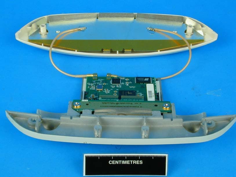
Click to zoom
Application Details
- Equipment Class
- NII - Unlicensed National Information Infrastructure TX
- Date of Grant
- Oct 22, 2003
- Application Purpose
- Original Equipment
- Date of Application
- Oct 22, 2003
- Equipment Note
- UNII Wireless RLAN and host
- Frequency Range
- 5725.00000000 - 5825.00000000
- Company
- Symbol Technologies Inc
- Country
- United States
Documents & Files
Document Text
Text extracted from the exhibit documents filed with the FCC. Open a document above to read the original.
Users Manual
- 1 -Model 5030 Access Port Quick Reference Guide DRAFT V3 Symbol IEEE 802.11A/B Access Port (Model WSAP-5030-100-WW) Hardware Quick Reference Guide Draft March 2003 - 2 -Model 5030 Access Port Quick Reference Guide DRAFT V3 To The Installer ................................................................................................................................ 4 Purpose ....................................................................................................................................... 4 Document Conventions................................................................................................................ 4 Warnings:..................................................................................................................................... 4 Introduction ...................................................................................................................................... 5 Technical Specifications .............................................................................................................. 5 Radio Characteristics................................................................................................................... 6 Overview .......................................................................................................................................... 7 LED Indicators ............................................................................................................................. 7 Mounting hardware included:....................................................................................................... 7 Surface Mounting ........................................................................................................................... 11 Wall Mounting ............................................................................................................................ 11 Attaching the Access Port to the Mounting Bracket .............................................................. 11 Plaster Wall Board Ceiling Mount .............................................................................................. 12 Attaching the Access Port to the Mounting Bracket .............................................................. 12 Above Suspended Ceiling Tile (Plenum) Mount ........................................................................ 13 Attaching the Access Port to the Mounting Bracket .............................................................. 13 Below Suspended Ceiling (T-Bar) Mount................................................................................... 14 Attaching the Access Port to the Suspended Ceiling Mounting Bracket ............................... 14 Available Options ........................................................................................................................... 16 Customer Support .......................................................................................................................... 17 North American Contacts........................................................................................................... 17 International Contacts ................................................................................................................ 17 Symbol Developer Program Web Site ....................................................................................... 17 Legal Information ........................................................................................................................... 19 Regulatory Information............................................................................................................... 19 Applying the Regulatory Country Stamp.................................................................................... 19 - 3 -Model 5030 Access Port Quick Reference Guide DRAFT V3 If the appropriate stamp(s)is not provided, please contact your supplier..... 19 To apply the country stamp:.................................................................................................. 19 FCC RF Exposure Guidelines ....................................................................................... 20 Safety Information ..................................................................................................................... 20 Remote and Standalone Antenna Configurations. .................................................................... 20 Power Supply ............................................................................................................................ 20 Radio Frequency Interference Requirements ................................................................................ 21 Radio Frequency Interference Requirements – Canada ............................................................... 22 Statement of Compliance .......................................................................................................... 22 Other Countries ......................................................................................................................... 23 Copyright........................................................................................................................................ 24 Patents ...................................................................................................................................... 24 - 4 -Model 5030 Access Port Quick Reference Guide DRAFT V3 To the Installer This guide is intended for the technician responsible for installing Symbol Technologies IEEE 802.11a Access Port. It is assumed that the technician is familiar with Ethernet LAN-based networking, terms and concepts. The installing technician should also have a working knowledge of mechanical assembly as well as an understanding of local building codes. Purpose The purpose of this document is to provide specifications, features and guidelines for the installer to…
Text truncated - open the document above for the full version.
Users Manual
Regulatory compliance Symbol Technologies, Inc. Page 1 of 1 Hydra FCC RF Exposure Sept 03 Hydra (WSAP-5030) and FCC RF Exposure FCC ID: H9PWSAP5030. The User Guide for the WSAP5030 will be amended as follows: Delete: “It is advisable to use the device only in the normal operating position and it is recomended that no part of the human body be allowed to come too close to the antenna during operation of the equipment”. Add: “It is advisable to use the device only in the normal operating position”. Maintain: “To comply with FCC RF exposure requirements, antennas that are mounted externally at remote locations or operating near users at stand-alone desktop of similar configurations must operate with a minimum separation distance of 20 cm from all persons” I trust the information I have provided will enable an FCC Grant to be obtained. Signed for Symbol Technologies Inc. Alan Parrish Director, Regulatory
Users Manual
Regulatory compliance Symbol Technologies, Inc. Page 1 of 1 Hydra FCC Accessories Sept 03 Hydra (WSAP-5030) and Approved Accessories FCC ID: H9PWSAP5030. Symbol Technologies designs, manufacturers and supplies product into International Markets. The User Guide for the WSAP5030 is Generic and therefore covers all the intended International markets that Symbol Technologies will supply into. The user Guide includes accessories that may not be available in all markets. To control this situation and to ensure only approved accessories are supplied into the particular country, Symbol has a release process. Products can only be shipped into a country when released. A release will only be granted when approval has been gained in the particular country for that particular accessory. To further ensure only approved products are shipped and operated, Symbol Regulatory are part of and required to “sign-off” a products for release. This will ensure only approved products will be shipped and operated. I trust the information I have provided will enable an FCC Grant to be obtained. Signed for Symbol Technologies Inc. Alan Parrish Director, Regulatory
Cover Letter(s)
Symbol Technologies, Inc. • One Symbol Plaza, Holtsville, NY 11742-1300 • 1.631.738.5134 • www.symbol.com December 23, 2004 Regulatory Engineering FCC Correspondence Reference Number:16131 FCC ID: H9PWSAP5030 Subject: Country of Use 1) There is a complaint from a competitor that this device can have the user select the country of use codes. This is not permitted since the Japan frequencies would permit operation in the restricted bands if improperly selected. I reviewed the application concerning this issue and am not clear on how you restrict operation of the Japan frequencies for US operation. The User's Manual is titled Quick Reference Guide and may not be the final complete version. Some exhibits say that the device should be installed by a technician but does not distinctly say "professional installation required." The Grant condition does not state professional installation. In addition you state that the device can be configured with accessories that are only marketed to countries that would permit their use. I thought that this was the method used to prevent unauthorized operation but am not clear. In addition you state that there are country stamps that must be placed on the device which lends me to believe that the device is configured to operate in all countries including use of the Japanese frequencies. Please clarify that the user cannot use a country selectable code to select the frequency plan. How is this controlled? Symbol Response to Correspondence Reference Number:16131 Dear Mr Leimer, Following the FCC query to the ITI Trade Association on the ability of consumers to select and configure Wi-Fi access points outside the authorized band. Symbol (Dornu Narnor and Mark Luksich) met with the FCC (Rich Fabina, Rashmi Doshi, and Tim Harrington) to discuss this issue. At the meeting, Symbol demonstrated a Symbol Access Point and the set-up process. The following conditions are used by Symbol and met with the FCC’s approval: 1. Configuration of the System is by the installer and requires password access. 2. There are warning screens displayed when the system is being configured. 3. The “User” has no access to the System configuration. The particular unit that you are referencing (WSAP-5030) is an RF Port that is connected to a Wireless Switch. The system configuration is managed through the Wireless Switch. It should be noted that these systems are professionally installed and maintained by Symbol or under contract by ‘Symbol Certified’ companies. The 3 conditions listed above have been implemented in the wireless switch software. This type of product is targeted at the industrial users such as: Target, Sears, Avis, Wal-Mart and not the consumer market through outlets such as KMART and Best Buy. Respectfully, Mark S. Luksich Director, Regulatory Engineering 631-738-5134 [email protected]
External Photos
Exhibit 3 Please see TUVPS report nos. OR610776-04 and OR610776-06
ID Label/Location Info
Regulatory compliance Symbol Technologies, Inc. Page 1 of 1 Hydra FCC Statements Sept 03 Hydra (WSAP-5030 & WSM-5030) and FCC statements Reference FCC Rule 15.19 (a) (5) FCC ID: H9PWSAP5030. The WSAP-5030 is a Wireless LAN (Local Area Network) offering dual mode IEEE 802.11b and IEEE 802.11a Technologies operating at 2.4 and 5GHZ frequency bands. Given the complexity of this product and requirement to operate continuously at relatively high temperatures, the face available for Regulatory Markings and Manufacturing Information is severely restricted, as we required a maximum amount of surface area for heat sinking. With regard the required FCC statements, given the situation described above, we have placed the required statements into the product User Guide. The product will exhibit the FCC Logo and the FCC ID: H9PWSAP5030. FCC ID: H9PWSM5030. The WSM-5030 is a Module for use with the WSAP-5030 delivering the IEEE 802.11b Technology part operating at 2.4GHz. Given size of this plug in module the space available for Regulatory Markings and Manufacturing Information is severely restricted. With regard the required FCC statements, given the situation described above, we have placed the required statements into the product User Guide. The product will exhibit the FCC Logo and the FCC ID: H9PWSM5030. I trust the information I have provided will enable an FCC Grant to be obtained. Signed for Symbol Technologies Inc. Alan Parrish Director, Regulatory
Internal Photos
Exhibit 9 Please see TUVPS report nos. OR610776-04 and OR610776-06
Internal Photos
BABT Product Service Ltd, Segensworth Road, Titchfield Fareham, Hampshire, United Kingdom, PO15 5RH Tel: +44(0) 1329 443459, Fax: +44(0) 1329 443331 www.tuvps.co.uk BABT Product Service Reference Number OR610776 Page 1 of 7 FCC ID: H9PWSM5030 Re:FCC ID:H9PWSAP5030 Applicant: Symbol Technologies Inc Correspondence Reference Number: 10077 731 Confirmation Number: TC459537 Date of Original Email: 11/10/2003 Question:- Item 4) Filing does not include sufficient user manual, external photo, and/or test setup photos to determine how 2.4ghz card module relates to AP case with 4 antennas, and how card is installed and used. Please clarify. Response:- The photograph in test report OR610776 page 165 shows both "rubber duck" antenna installed for WSAP5030 The photograph in test report OR610776 page 169 shows UNII internal antenna installed. The photograph in test report OR610776 page 170 shows both "rubber duck" antenna the pair on the right are the 2.4GHz antenna. The following photographs show how the 2.4GHZ module relates to the AP case with 4 antennas. BABT Product Service Ltd, Segensworth Road, Titchfield Fareham, Hampshire, United Kingdom, PO15 5RH Tel: +44(0) 1329 443459, Fax: +44(0) 1329 443331 www.tuvps.co.uk BABT Product Service Reference Number OR610776 Page 2 of 7 FCC ID: H9PWSM5030 Photo 1; WSAP5030 External Antenna connections BABT Product Service Ltd, Segensworth Road, Titchfield Fareham, Hampshire, United Kingdom, PO15 5RH Tel: +44(0) 1329 443459, Fax: +44(0) 1329 443331 www.tuvps.co.uk BABT Product Service Reference Number OR610776 Page 3 of 7 FCC ID: H9PWSM5030 Photo 2; WSAP5030 External Antenna connections 2.4GHz module un-iinstalled BABT Product Service Ltd, Segensworth Road, Titchfield Fareham, Hampshire, United Kingdom, PO15 5RH Tel: +44(0) 1329 443459, Fax: +44(0) 1329 443331 www.tuvps.co.uk BABT Product Service Reference Number OR610776 Page 4 of 7 FCC ID: H9PWSM5030 Photo 3; WSM5030 2.4GHz Integral Antenna Outside Case Rear BABT Product Service Ltd, Segensworth Road, Titchfield Fareham, Hampshire, United Kingdom, PO15 5RH Tel: +44(0) 1329 443459, Fax: +44(0) 1329 443331 www.tuvps.co.uk BABT Product Service Reference Number OR610776 Page 5 of 7 FCC ID: H9PWSM5030 Photo 4; WSM5030 2.4GHz Integral Antenna Outside Case Rear Showing Connection to WSAP5030 BABT Product Service Ltd, Segensworth Road, Titchfield Fareham, Hampshire, United Kingdom, PO15 5RH Tel: +44(0) 1329 443459, Fax: +44(0) 1329 443331 www.tuvps.co.uk BABT Product Service Reference Number OR610776 Page 6 of 7 FCC ID: H9PWSM5030 Photo 5; WSM5030 2.4GHz Integral Antenna Outside Case Front Showing Connection to WSAP5030 BABT Product Service Ltd, Segensworth Road, Titchfield Fareham, Hampshire, United Kingdom, PO15 5RH Tel: +44(0) 1329 443459, Fax: +44(0) 1329 443331 www.tuvps.co.uk BABT Product Service Reference Number OR610776 Page 7 of 7 FCC ID: H9PWSM5030 Photo 6; Internal of Integral Antenna
RF Exposure Info
BABT. Segensworth Road, Titchfield Fareham, Hampshire, United Kingdom, PO15 5RH Tel: +44(0) 1329 443300, Fax: +44(0) 1329 443331 www.babt.com Page 1 of 2 FCC ID H9PWSAP5030 MPE Calculation For Symbol Hydra Wireless LAN The Symbol Hydra device consists of a 2.4GHz and a 5GHz transmitter. The far field regions below are calculated for both the 2.4GHz and 5GHz frequencies. To establish the worst-case scenario, it is assumed that there is an additive effect of the 2.4GHz and 5GHz powers. Firstly, the worst-case distance to be in the far field is established for both frequencies: 5GHz The wavelength of the equipment is: 3x10 8 = 0.05m 5805 x10 6 Thus, the far field region is defined as being: λ = 0.05 = 0.008m or 8mm 2p 6.283 2.4GHz The wavelength of the equipment is: 3x10 8 = 0.12m 2462 x10 6 Thus, the far field region is defined as being: λ = 0.12 = 0.019m or 19mm 2p 6.283 So, taking both maximum power readings and combining: 50.7mW + 69.18mW = 119.88mW Therefore, the formula below is applicable for distances that are in the far field. Thus, predicting the worst case RF Power Density at 20cm from the antenna would be: S = P x G = 119.88 x 1.58 =0.038mW/cm 2 4pR 2 12.57 x 20 2 where: P = power measured in mW G = antenna gain as numeric gain, (1.58 numeric / 2.0dBi) R = distance in cm BABT. Segensworth Road, Titchfield Fareham, Hampshire, United Kingdom, PO15 5RH Tel: +44(0) 1329 443300, Fax: +44(0) 1329 443331 www.babt.com Page 2 of 2 FCC ID H9PWSAP5030 MPE Calculation For Symbol Hydra Wireless LAN - continued MPE for Occupational/Controlled Exposure at 2462MHz is 5mW/cm 2 MPE for General Population/Uncontrolled Exposure at 2462MHz is 1mW/cm 2 MPE for Occupational/Controlled Exposure at 5280MHz is 5mW/cm 2 MPE for General Population/Uncontrolled Exposure at 5280MHz is 1mW/cm 2 Therefore, the unit under test has a power density, which is less than both the General Population and Occupational exposure limits whilst both transmitters are operating. This is deemed the worst-case configuration for the equipment under test.
RF Exposure Info
BABT. Segensworth Road, Titchfield Fareham, Hampshire, United Kingdom, PO15 5RH Tel: +44(0) 1329 443300, Fax: +44(0) 1329 443331 www.babt.com Page 1 of 2 FCC ID H9PWSAP5030 MPE Calculation For Symbol Hydra Wireless LAN A 5GHz Spread Spectrum device has a measured output power of 69.18mW with a worst- case antenna gain of 2.5dBi. The equipment can operate in the bands listed in the table below. The equipment is proposed as meeting the OET65 requirements for use at 20cm. The wavelength of the equipment is: 3x10 8 = 0.05m 5805 x10 6 Thus, the far field region is defined as being: λ = 0.05 = 0.008m or 8mm 2p 6.283 Therefore, the formula below is applicable as any distance greater than 8mm is in the far field. Thus, predicting the worst case RF Power Density at 20cm from the antenna would be: S = P x G = 40.74x 1.78 = 0.014mW/cm 2 4pR 2 12.57 x 20 2 where: P = power measured in mW G = antenna gain as numeric gain, (1.78 numeric / 2.5dBi) R = distance in cm MPE for Occupational/Controlled Exposure at 5805MHz is 5mW/cm 2 MPE for General Population/Uncontrolled Exposure at 5805MHz is 1mW/cm 2 Therefore, the unit under test has a power density, which is less than both the General Population and Occupational exposure limits. This is the case for the equipment under test in all conditions of operation. The table below shows the Power Density result for each channel and antenna configuration. Antenna Gain Frequency (MHz) Measured Conducted Power (mW) dBi Numeric Power Density (mW/cm 2 ) 5180 46.24 2.5 1.78 0.016 5180 46.24 2 1.58 0.015 5220 48.02 2.5 1.78 0.017 5220 48.02 2 1.58 0.015 5240 48.08 2.5 1.78 0.017 5240 48.08 2 1.58 0.015 BABT. Segensworth Road, Titchfield Fareham, Hampshire, United Kingdom, PO15 5RH Tel: +44(0) 1329 443300, Fax: +44(0) 1329 443331 www.babt.com Page 2 of 2 FCC ID H9PWSAP5030 MPE Calculation For Symbol Hydra Wireless LAN - continued Antenna Gain Frequency (MHz) Measured Conducted Power (mW) dBi Numeric Power Density (mW/cm 2 ) 5260 68.39 2.5 1.78 0.024 5260 68.39 2 1.58 0.021 5280 69.18 2.5 1.78 0.024 5280 69.18 2 1.58 0.022 5320 60.26 2.5 1.78 0.021 5320 60.26 2 1.58 0.019 Antenna Gain Frequency (MHz) Measured Conducted Power (mW) dBi Numeric Power Density (mW/cm 2 ) 5745 46.24 2.5 1.78 0.016 5745 46.24 2 1.58 0.015 5805 40.74 2.5 1.78 0.014 5805 40.74 2 1.58 0.013
Test Report
TEST REPORT FCC Part 15 E Testing in support of an Application for Grant of Equipment Authorisation of a Symbol WSAP-5030 Access Port FCC ID: H9PWSAP5030 Report Number: OR610776/04/Issue 2October 2003 BABT. Segensworth Road, Titchfield Fareham, Hampshire, United Kingdom, PO15 5RH Tel: +44(0) 1329 443300, Fax: +44(0) 1329 443331 www.babt.com Report Number OR610776/04/Issue 2Page 1 of 174 REPORT ONFCC Part 15 E Testing in support of an Application for Grant of Equipment Authorisation of a Symbol WSAP-5030 Access Port FCC ID: H9PWSAP5030 Report No OR610776/04/Issue 2 October 2003 EQUIPMENT:WSAP-5030 Access Port FCC ID:H9PWSAP5030 SPECIFICATION:47 CFR 15 Subpart E, 2002-08 PREPARED FOR:Symbol Technologies Inc One Symbol Plaza Holtsville NY 11742-1300 New York United States of America MANUFACTURERS REPRESENTATIVE:Mr Alan Parrish APPROVED BY: C Gould UKAS Signatory DATED:10-10-03 DISTRIBUTIONSymbol TechnologiesCopy 1 (CD) TÜV Product ServiceCopy 2 Copy No Total No of Pages 174 Report Number OR610776/04/Issue 2Page 2 of 174 FCC ID: H9PWSAP5030 Table of Contents Page No STATUS...........................................................................................................................................................4 TEST RATIONALE .........................................................................................................................................5 SYSTEM CONFIGURATION ......................................................................................................................... 6 TEST SETUP PHOTOGRAPHS....................................................................................................................7 EQUIPMENT INFORMATION........................................................................................................................9 PART 1 – 5.15-5.25GHz RADIATED EMISSION MEASUREMENT AT THE BAND EDGE (MARKER DELTA METHOD).............13 PEAK OUTPUT POWER ...............................................................................................................................15 PEAK POWER SPECTRAL DENSITY..........................................................................................................16 EMISSION BANDWIDTH ...............................................................................................................................23 FREQUENCY STABILITY UNDER TEMPERATURE VARIATIONS ..........................................................30 SPURIOUS CONDUCTED EMISSIONS.......................................................................................................31 PEAK EXCURSION. .......................................................................................................................................35 SPURIOUS RADIATED EMISSIONS............................................................................................................42 PART 2 – 5.25-5.35GHz RADIATED EMISSION MEASUREMENT AT THE BAND EDGE (MARKER DELTA METHOD).............46 PEAK OUTPUT POWER ...............................................................................................................................48 PEAK POWER SPECTRAL DENSITY..........................................................................................................49 EMISSION BANDWIDTH ...............................................................................................................................56 FREQUENCY STABILITY UNDER TEMPERATURE VARIATIONS ..........................................................63 SPURIOUS CONDUCTED EMISSIONS.......................................................................................................64 PEAK EXCURSION. .......................................................................................................................................99 SPURIOUS RADIATED EMISSIONS............................................................................................................ 106 Report Number OR610776/04/Issue 2Page 3 of 174 FCC ID: H9PWSAP5030 Table of Contents-continued Page No PART 3 – 5.725-5.825GHz RADIATED EMISSION MEASUREMENT AT THE BAND EDGE (MARKER DELTA METHOD)............. 110 PEAK OUTPUT POWER ............................................................................................................................... 112 PEAK POWER SPECTRAL DENSITY.......................................................................................................... 113 EMISSION BANDWIDTH ............................................................................................................................... 120 FREQUENCY STABILITY UNDER TEMPERATURE VARIATIONS .......................................................... 127 SPURIOUS CONDUCTED EMISSIONS....................................................................................................... 128 PEAK EXCURSION. ....................................................................................................................................... 153 SPURIOUS RADIATED EMISSIONS............................................................................................................ 160 PHOTOGRAPHS OF EQUIPMENT .............................................................................................................. 163 MEASUREMENT UNCERTAINTY ................................................................................................................ 173 COPYRIGHT STATEMENT .......................................................................................................................... 174 FCC SITE COMPLIANCE LETTERS....................................................................................Annex A Report Number OR610776/04/Issue 2Page 4 of 174 FCC ID: H9PWSAP5030 STATUS OBJECTIVETo undertake measurements to determine the Equipment Under Test's (EUT's) compliance with the specification. MANUFACTURING DESCRIPTIONAccess Port APPLICANTSymbol Technologies Symbol Place Winnersh T…
Text truncated - open the document above for the full version.
Test Report
TEST REPORT Limited FCC Parts 15 C and E Testing (Co-Located Transmitters) for a Symbol WSAP-5030 Access Port and WSM-5030 RF Module FCC ID: H9PWSAP5030 & H9PWSM5030 Report Number: OR610776/06/Issue 2October 2003 BABT. Segensworth Road, Titchfield Fareham, Hampshire, United Kingdom, PO15 5RH Tel: +44(0) 1329 443300, Fax: +44(0) 1329 443331 www.babt.com Report Number OR610776/06/Issue 2Page 1 of 46 REPORT ONLimited FCC Parts 15 C and E Testing (Co-Located Transmitters) for a Symbol WSAP-5030 Access Port and WSM- 5030 RF Module Report No OR610776/06/Issue 2 October 2003 EQUIPMENT:WSAP-5030 Access Port and WSM-5030 RLAN Radio Module FCC ID:H9PWSAP5030 & H9PWSM5030 SPECIFICATION:47 CFR 15 Subparts C & E PREPARED FOR:Symbol Technologies Inc One Symbol Plaza Holtsville NY 11742-1300 New York United States of America MANUFACTURERS REPRESENTATIVE:Mr Alan Parrish APPROVED BY: C Gould UKAS Signatory DATED:10-10-03 DISTRIBUTIONSymbol TechnologiesCopy 1 (CD) TÜV Product ServiceCopy 2 Copy No Total No of Pages 46 Report Number OR610776/06/Issue 2Page 2 of 46 FCC ID: H9PWSAP5030 Table of Contents Page No STATUS...........................................................................................................................................................3 TEST RATIONALE..........................................................................................................................................4 SYSTEM CONFIGURATION ......................................................................................................................... 5 TEST SETUP PHOTOGRAPHS ....................................................................................................................6 EQUIPMENT INFORMATION........................................................................................................................8 PART 1 – 2.437GHz and 5.180GHz SPURIOUS CONDUCTED EMISSIONS....................................................................................................... 12 UNDESIRABLE AND SPURIOUS RADIATED EMISSIONS. ...................................................................... 14 PART 2 – 2.437GHz and 5.280GHz SPURIOUS CONDUCTED EMISSIONS....................................................................................................... 19 UNDESIRABLE AND SPURIOUS RADIATED EMISSIONS. ...................................................................... 21 PART 3 – 2.437GHz and 5.830GHz SPURIOUS CONDUCTED EMISSIONS....................................................................................................... 26 UNDESIRABLE AND SPURIOUS RADIATED EMISSIONS. ...................................................................... 28 PHOTOGRAPHS OF EQUIPMENT .............................................................................................................. 32 MEASUREMENT UNCERTAINTY ................................................................................................................ 45 COPYRIGHT STATEMENT .......................................................................................................................... 46 FCC SITE COMPLIANCE LETTERS....................................................................................Annex A Report Number OR610776/06/Issue 2Page 3 of 46 FCC ID: H9PWSAP5030 STATUS OBJECTIVETo undertake measurements to determine the Equipment Under Test's (EUT's) compliance with the specification. MANUFACTURING DESCRIPTIONAccess Port and RLAN Radio Module APPLICANTSymbol Technologies Symbol Place Winnersh Triangle Berkshire RG41 5TP MANUFACTURERS TYPE NUMBERWSAP-5030 and WSM-5030 MANUFACTURERS PART NUMBERWSAP-5030 and WSM-5030 SERIAL NUMBERNo 5 HARDWARE REVISIONDVT3.1 TEST SPECIFICATION NUMBERFCC Part 15 Subparts C and E, 2002-08 REGISTRATION NUMBEROR610776 QUANTITY OF ITEMS TESTEDOne SECURITY CLASSIFICATION OF EUTUnclassified INCOMING RELEASEDeclaration of Build Status SERIAL NUMBER610776 DATE29 th June 2003 DISPOSALHeld pending disposal REFERENCE NUMBERN/A DATEN/A START OF TEST5 th July 2003 FINISH OF TEST15 th August 2003 TEST ENGINEERSBob Bennett Anthony Guy Phil Harrison Graeme Lawler Malcolm Terry RELATED DOCUMENTSANSI C63.4 200…
Text truncated - open the document above for the full version.
Contact Information
Applicant
Qianlin Zhou(Regulatory Specialist)
Test Firm
TUV SUD Product ServiceJensen Adams
Technical Specifications
| # | Rule Parts | Frequency Range | Power Output |
|---|---|---|---|
| 3 | 15E | 5.72 GHz - 5.83 GHz | 46.20 mW |
Other Applications from Symbol Technologies Inc

H9PCCHUB1
Jun 30, 2015Customer Concierge
Equipment Class
NII - Unlicensed National Information Infrastructure TX
H9PAP7562
May 10, 2015802.11 abgn/ac Access Point
Equipment Class
DTS - Digital Transmission System
H9PTC75AH
Mar 26, 2015Touch Computer
Equipment Class
NII - Unlicensed National Information Infrastructure TX
H9PRA1202
Sep 24, 2014UHF Narrowband Radio Module
Equipment Class
TNB - Licensed Non-Broadcast Station Transmitter
H9PEMG101
Aug 26, 2014802.15.4 Gateway
Equipment Class
DTS - Digital Transmission System