H9PWWC1002SW86S12400 MHz Wireless Printer
Symbol Technologies Inc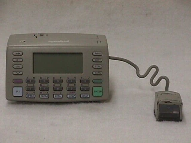
Click to zoom
Application Details
- Equipment Class
- DXX - Part 15 Low Power Communication Device Transmitter
- Date of Grant
- May 04, 1999
- Application Purpose
- Original Equipment
- Date of Application
- Mar 11, 1999
- Equipment Note
- 2400 MHz Wireless Printer
- Frequency Range
- 2481.90000000 - 2481.90000000
- Company
- Symbol Technologies Inc
- Country
- United States
Documents & Files
Document Text
Text extracted from the exhibit documents filed with the FCC. Open a document above to read the original.
Users Manual
WSS 1000 Quick Reference Quick Reference 1997 SYMBOL TECHNOLOGIES, INC. All rights reserved. Symbol reserves the right to make changes to any product to improve reliability, function, or design. Symbol does not assume any product liability arising out of, or in connection with, the application or use of any product, circuit, or application described herein. No license is granted, either expressly or by implication, estoppel, or otherwise under any patent right or patent, covering or relating to any combination, system, apparatus, machine, material, method, or process in which Symbol products might be used. An implied license only exists for equipment, circuits, and subsystems contained in Symbol products. Symbol Technologies, Inc. One Symbol Plaza Holtsville, N.Y. 11742-1300 1 Introduction The WSS 1000 is a wearable data entry system consisting of a laser bar code scanner (RS 1) worn on the operator ’ s fingers, and a wrist computer (WWC 1000) worn on the operator ’s forearm. The detachable components work equally well for right- and left-handed individuals. Detachable personal mounts allow multiple operators to share both ring scanner and wrist computer without having to use the same mount. About This Guide This guide presents information on system components, assembling the system, battery installation and charging, attaching the system, using the keyboard and scanner, and disassembly for use by others. 2 Quick Reference Parts of the WSS 1000 System Keyboard Display Speaker Battery Latch Power Switch Battery Charging Contacts Lithium-Ion Battery WWC 1000 Top WWC 1000 (Wrist Computer) Front Adjustable Straps Snap-On Bar WWC 1000 Wrist Mount 3 Scan Window Scan Trigger Mount Release Button Scan/Decode LED Interface Port RS 1 (Ring Scanner) Front RS 1 Back RS 1 Moun Ring Mount Straps 4 Quick Reference Installing and Charging the Battery The wrist computer and scanner are powered by a Lithium-Ion battery pack. The pack provides power for a typical 8-hour shift. Note:Before using the wrist computer, install and ful- ly charge the Lithium-Ion battery pack. To install the battery pack in the WWC 1000: 1. Insert the battery pack, base first, in the battery compartment. 2. Line up the pack’s locking mechanism with the notch in the battery compartment wall by sliding the battery latch, and press the pack into place. 3. Release the battery latch to lock in place. Battery Latch Notch Battery Compartment Battery Pack Base 5 Charging the Battery in WWC 1000 To charge the Lithium-Ion battery in the WWC 1000: 1. Place the WWC 1000 in the cradle as shown below: 2. The cradle’s CHARGING light illuminates (RED) if the WWC 1000 is properly seated and the battery is charging. 3. The battery requires approximately 2 hours to charge fully. The CHARGING light changes to GREEN when the battery is fully charged. 4. To remove the WWC 1000 from the cradle, tilt the WWC 1000 upward and pull out. For more information on the CS 1000 Cradle, refer to the CS 1000 4-Slot Cradle QRG, p/n 70-17661-0X. 6 Quick Reference Charging the Spare Battery Spare battery packs can be charged separate from the WWC 1000. To charge a spare battery pack in the cradle: 1. Insert the pack in the cradle’s spare charging slot. 2. The CHARGING light illuminates red. 3. The spare pack is charged in approximately two hours, even if the WWC 1000 is charging at the same time. The CHARGING light changes to green when the battery is fully charged. 7 Assembling the WSS 1000 System To assemble the WWC 1000 (wrist computer): 1. Place the WWC 1000 wrist computer onto the wrist mount, facing you. Be sure the mount is oriented so that the longer strap will be further up the forearm. 2. Snap the bar over the WWC 1000 using the snaps on either side of the mount. The straight part of the bar should lay across the front of the WWC 1000; the curved part in back. 8 Quick Reference Note:The snaps on the wrist mount act as a tear-away device allowing the wrist computer to detach from the mount if it catches on an object. To assemble the RS 1 (ring scanner): 1. Adjust the strap of the ring mount to fit your right or left index and middle fingers: a. Slip the mount onto your right or left index and middle fingers, oriented so the trigger is next to your thumb. b. If necessary, adjust the strap so that the mount fits comfortably. c. Remove the mount. 9 2. Insert the ring scanner in the ring mount, depending on right- or left-handed use. a. Determine whether the scanner will be used on the right or left arm. b. Orient the ring scanner to the mount so that the trigger is next to the operato r’s thumb. c. Slide the ring scanner backwards into the mount. 3. Plug the cable connector from the WWC 1000 in the interface port on the back of the ring scanner, with the arrow on the top of the cable facing up. 10 Quick Reference Place the WSS 1000 system on your arm: 1. Slide the wrist mount on your arm, so that the WWC 1000 wrist computer faces you. 2. Pull the straps through the buckles so the wrist mount is secure but not tight. 3. Use the Velcro to secure the straps. 11 4. Slide the ring mount and scanner on your right or left index and middle fingers with the trigger next to your thumb. 12 Quick Reference Power Once the battery pack is fully charged, you are ready to use the wrist computer. To power the wrist computer on, press the power switch on top of the WWC 1000. Display Light and Contrast To turn the display light and keypad backlight on, press LAMP (Left Alpha and Help). To adjust the contrast: •press FUNC and SPACE to darken the contrast, •press FUNC and BKSP to lighten the contrast. 13 Communicating with the Host Using the Cradle The CS 1000 cradle is used to perform communications with a host PC. To set up the cradle for operation: 1. Plug one end of a null modem cable (p/n 59846-03- 00) into the communications port located on the left end of the cradle. 2. Connect the other end of the cable to the host computer ’s serial (COMM) port. 3. Provide power to the c…
Text truncated - open the document above for the full version.
Users Manual
Regulatory Addendum Radio Frequency Interference Requirements This device has been tested and found to comply with the limits for a Class A digital device pursuant to Part 15 of the Federal Communications Rules and Regulation. These limits are designed to provide reasonable protection against harmful interference when the equipment is operated in a commercial environment. This equipment generates, uses, and can radiate radio frequency energy and, if not installed and used in accordance with the instruction manual, may cause harmful interference to radio communications. Operation of this equipment in a residential is likely to cause harmful interference in which case the user will be required to correct the interference at his own expense. However, there is no guarantee that interference will not occur in a particular installation. If the equipment does cause harmful interference to radio or television reception, which can be determined by turning the equipment off and on, the user is encouraged to try and correct the interference by one of the following measures: • Re-orient or relocate the receiving antenna. • Increase the separation between the equipment and receiver. • Connect the equipment into an outlet on a circuit different from that which the receiver is connected. • Consult the dealer or an experienced radio/TV technician for help. This device complies with FCC Part 15. Operation is subject to the following two conditions: (1) this device may not cause harmful interference and (2) this device must accept any interference received, including interference that may cause undesired operation.” Radio Frequency Interference Requirements- Canada This device complies with RSS 210 of Industry & Science Canada. Operation is subject to the following two conditions: (1) this device may not cause harmful interference and (2) this device must accept any interference received, including interference that may cause undesired operation.” This Class A digital apparatus meets the requirements of the Industry Canada Standard ICES-003. Cet appareil numerique de la Classe A est conforme a la norme NMB-003 du Canada. CE Marking and European Union Compliance Products intended for sale within the European Union are marked with the CE Mark which indicates compliance to applicable Directives and European Normes (EN), as follows, Amendments to these Directives or ENs are included: Applicable Directives • Electromagnetic Compatibility Directive 89/336/EEC • Low Voltage Directive 73/23/EEC Applicable Standards • EN 55022-Limits and Methods of Measurement of Radio Interference Characteristics of Information technology Equipment • EN 50 082-1:1997-Electromagnetic Compatibility-Generic Immunity Standard, Part 1: Residential, commercial, Light Industry. • IEC 1000-4-2(1995-01)-Electromagnetic Compatibility (EMC) – Part 4: Testing and measurement techniques-Section 2: Electrostatic Discharge immunity test. • IEC 1000-4-3(1995-03)-Electromagnetic Compatibility (EMC) –Part 4: Testing and measurement techniques-Section 3: Radiated, radio-frequency electromagnetic field immunity test. • IEC 1000-4-4(1995-01)-Electromagnetic Compatibility (EMC) –Part 4: Testing and measurement techniques-Section 4: Electrical Fast transient /burst immunity test. • EN 60 950+Amd1 + Amd @-Safety of Information Technology Equipment Including Electrical Business Equipment • EN 60 825-1 (EN 60 825)- Safety of Devices Containing Lasers Laser Devices Symbol products using lasers comply with US 21 CFR1040.10, Subchapter J and IEC 825/EN 60 825 (or IEC 825-1/EN 60 825-1, depending on the date of manufacture). The laser classification is marked on one of the labels on the product. Class 1 Laser devices are not considered hazardous when used for their intended purpose. The following statement is required to comply with US and international regulations: Caution: Use of controls, adjustments or performance of procedures other than those specified herein may result in hazardous laser light exposure. Class 2 laser scanners use a low power visible light diode. As with any very bright light source such as the sun, the user should avoid staring directly into the light beam. Momentary exposure to a Class 2 laser is not known to be harmful. RF Devices Symbol’s RF products are designed to be compliant with the rules and regulations in the locations into which they are sold and will be labeled as required. The majority of Symbol’s RF devices are type approved and do not require the user to obtain license or authorization before using the equipment. Any changes or modifications to Symbol Technologies equipment not expressly approved by Symbol Technologies could void the user’s authority to operate the equipment.
Attestation Statements
Sandy Mazzola Symbol Technologies, Inc. 1 Symbol Plaza Holtsville, N.Y. 11742 Voice : (516) 738-5373 Fax: (516) 738-3318 Letter of Confidentiality Request Dear Reviewer, Symbol Technologies (“Symbol”), requests that the Block Diagram, Schematics, and operational Description exhibits of the referenced application be withheld from routine availability for public inspection pursuant to Section 0.459 of the Commissions Rules an Freedom of Information Act (“FOIA) Exemption 4, 5 U.S.C. 552 (b) (4). These exhibits consist of “trade secrets (or) commercial or financial information obtained from a person and privileged or confidential” 5 U.S.C. 552 (b) (4), and is therefore entitled to protection from disclosure under FOIA. The documents in question contain trade secrets: detailed technical descriptions, specifications and schematics for a product to be offered for sale. These materials provide particulars on the product design. This information would give Symbol’s competitors an unearned and unwarranted competitive advantage. The documents contain “commercial information” within the scope of FOIA exemption 4. This information is the product of Symbol’s investment of money, personnel, and other resources. The result of the investment is a fairly earned position in the marketplace. Premature release of the information threatens substantial and unwarranted harm to Symbol’s competitive position. For these reasons, Symbol has taken pains to keep this technical information confidential, and intends to continue doing so. Symbol customarily witholds this information from persons outside the employ of Symbol and certain of its suppliers and contractors, and even within these groups routinely limits access to persons having a particular need for the information. If the Commissions were to make these documents public, it would be giving away hard won fruits of Symbols labors without compensation. The filing fee that is required for this confidentiality request is included in the check that accompanies this application. If there are any questions about this request, please call me at the number above. Thank you for your attention. Respectfully submitted, Sandy Mazzola
ID Label/Location Info
Sample FCC Label Symbol Technologies Inc. Model: WWC1002-SW86S1US FCC ID: H9PWWC1002SW86S1 This device complies with Part 15 of the FCC rules. Operation is subject to the following two conditions: (1) this device may not cause harmful interference and (2) this device must accept any interference received, including interference that may cause undesired operation. This is a sample draft of the label that will be located on the underside of the product. Sandy Mazzola
Parts List/Tune Up Info
REVISION (^=EXIT) ? *DATE? * LI,201,1.MDATAB40 SYMBOL TECHNOLOGIES, INC. ASK REL. 8.2 REQUESTOR: RACHMANL.BCSD .SYMBOLFRI, FEB 5, 1999, 12:40 PM INDENTED BILL OF MATERIAL PAGE NO: 1 ========================= AS OF 02/05/99 CLASS CODE GROUP: 1 PRODUCT LINECLASS CODE: 8707 UNCLASSIFIED OP: ORDER POLICY CODE WWC1002-SW86S1US OPCODE: 4 REV: .3 WU:BATCH-8L-640K-SRR 2.4GHZ WAMODEL: SOURCE: MECO NO: PPD43107DATE OF LAST ECO: 12/20/98 DAYS O ITEM QTY PER YIELD OFF REFERENCE EFFECTIV OBSOLETE PART NUMBER DESCRIPTION P RV NO. ASSEMBLY FACTR UM SC SET DESIGNATOR DATE DATE1-2-3-4-5-6-7-8-9----------------- ------------------------------ - -- ----- -------- ----- -- -- --- ---------- -------- --------#REV-1 0 0 .000 1.000 EA XX 0 PPD42102 10/20/98 99/99/99 #REV-2 0 0 .000 1.000 EA XX 0 PPD42674 11/21/98 99/99/99 #REV-3 0 0 .000 1.000 EA XX 0 PPD43107 12/20/98 99/99/99 31-10976-13 PSEUDO:SFW,NVM,S24,1.2M FLASH 0 *D 109 1.000 1.000 EA X 0 00/00/00 99/99/99 #REV-A 0 0 .000 1.000 EA XX 0 #EDR17696 03/26/96 99/99/99 #REV-B 0 0 .000 1.000 EA XX 0 D4207 03/02/97 99/99/99 #REV-C 0 0 .000 1.000 EA XX 0 D4314 03/22/98 99/99/99 #REV-D 0 0 .000 1.000 EA XX 0 D4331 05/10/98 99/99/99 63018-04-00 SFW:V3.03-03,S24N,63018-04.HEX 0 *A 1 .000 1.000 EA MX 0 05/10/98 99/99/9970-16727-07 SUPPL:SFW,FAT,S24 S3K 0 .A 3 .000 1.000 EA XX 0 05/10/98 99/99/99 31-16265-01 PSEUDO:KEYPAD,GENERIC 0 .B 104 1.000 1.000 EA X 0 00/00/00 99/99/99 #REV-A 0 0 .000 1.000 EA XX 0 #EDR19167 07/12/96 99/99/99 #REV-B 0 0 .000 1.000 EA XX 0 E3016 12/07/97 99/99/99 28-15965-05 KYPD:SCRND 27 POS-STD PARALYNE 3 .B 40 1.000 1.000 EA P 0 12/07/97 99/99/99 #REV-A 0 0 .000 1.000 EA XX 0 #EDR34811 10/13/97 99/99/99 #REV-B 0 0 .000 1.000 EA XX 0 E3238 12/07/97 99/99/99 28-15965-00 KEYPAD:27 POS,WRIST UNIT 3 .A 2 1.000 1.000 EA X 0 00/00/00 99/99/99 31-31288-01 PSEUDO:HSG SET 0 .B 102 1.000 1.000 EA X 0 00/00/00 99/99/99 #REV-1 0 0 .000 1.000 EA XX 0 PPD32732 04/28/97 99/99/99 #REV-2 0 0 .000 1.000 EA XX 0 PPD35906 11/10/97 99/99/99 #REV-A 0 0 .000 1.000 EA XX 0 #EDR38472 03/26/98 99/99/99 #REV-B 0 0 .000 1.000 EA XX 0 E4682A 11/01/98 99/99/99 10/01/98 11-15916-02 BUTTON:PWR SWITCH, MED GRY 3 .B 13 1.000 1.000 EA P 0 00/00/00 99/99/9921-31284-01 HSG ASSY:PL,BOTTOM,WRIST UNIT 3 .A 11 1.000 1.000 EA P 0 00/00/00 99/99/99 #REV-1 0 0 .000 1.000 EA XX 0 PPD32731 04/28/97 99/99/99 #REV-2 0 0 .000 1.000 EA XX 0 PPD35592 10/01/97 99/99/99 #REV-A 0 0 .000 1.000 EA XX 0 #EDR38472 03/26/98 99/99/99 11-31285-01 HSG:BOTTOM,WRIST,S24,MED GRY 0 .A 10 1.000 1.000 EA P 0 00/00/00 99/99/9912-16111-04 SPRING:EJECTOR 3 .A 11 1.000 1.000 EA P 0 10/01/97 99/99/9921-31284-XX HSG ASSY:VA,BOTTOM 0 .B 1 .000 1.000 EA XX 0 00/00/00 99/99/99 21-35380-02 HSG ASSY:PL,TOP,STND 3 .B 10 1.000 1.000 EA P 0 11/01/98 99/99/99 #REV-A 0 0 .000 1.000 EA XX 0 #EDR39436 07/14/98 99/99/99 #REV-B 0 0 .000 1.000 EA XX 0 E5344 11/08/98 99/99/99 11-08452-01 VENT:MEMBRANE,GORE-TEX 3 .C 13 1.000 1.000 EA P 0 00/00/00 99/99/9911-19521-01 BEZEL:DISPLAY 3 .A 12 1.000 1.000 EA X 0 00/00/00 99/99/9911-33688-02 HSG:TOP,WRIST,GRY MED 3 .A 10 1.000 1.000 EA P 0 11/08/98 99/99/99 11-33829-01 GASKET:SINGLE SIDE,COATED 3 .A 15 2.000 1.000 EA P 0 00/00/00 99/99/9916-17084-01 WINDOW:PLATE 3 .B 14 1.000 1.000 EA X 0 00/00/00 99/99/9921-35380-XX HSG ASSY:VA,TOP-TAPE 0 .A 1 .000 1.000 EA XX 0 00/00/00 99/99/9968-16563-01 PADPRINT:HSG,TOP,GENERIC 0 .B 11 .000 1.000 EA XX 0 00/00/00 99/99/99 LI,201,1.MDATAB40 SYMBOL TECHNOLOGIES, INC. ASK REL. 8.2 BOHEMIA - MANUFACTURING SYSTEMFRI, FEB 5, 1999, 12:40 PM INDENTED BILL OF MATERIAL PAGE NO: 2 ========================= AS OF 02/05/99 CLASS CODE GROUP: 1 PRODUCT LINECLASS CODE: 8707 UNCLASSIFIED OP: ORDER POLICY CODE WWC1002-SW86S1US OPCODE: 4 REV: .3 WU:BATCH-8L-640K-SRR 2.4GHZ WAMODEL: SOURCE: MECO NO: PPD43107DATE OF LAST ECO: 12/20/98 DAYS O ITEM QTY PER YIELD OFF REFERENCE EFFECTIV OBSOLETE PART NUMBER DESCRIPTION P RV NO. ASSEMBLY FACTR UM SC SET DESIGNATOR DATE DATE1-2-3-4-5-6-7-8-9----------------- ------------------------------ - -- ----- -------- ----- -- -- --- ---------- -------- --------31-31517-03 PSEUDO:COMMON PARTS,SATURN S24 0 .C 103 1.000 1.000 EA X 0 00/00/00 99/99/99 #REV-1 0 0 .000 1.000 EA XX 0 PPD38313 03/13/98 99/99/99 #REV-2 0 0 .000 1.000 EA XX 0 PPD38513 03/19/98 99/99/99 #REV-A 0 0 .000 1.000 EA XX 0 #EDR38472 03/26/98 99/99/99 #REV-A1 0 0 .000 1.000 EA XX 0 E4176 04/12/98 99/99/99 #REV-B 0 0 .000 1.000 EA XX 0 E4076 07/01/98 99/99/99 #REV-C 0 0 .000 1.000 EA XX 0 E4954A 10/16/98 99/99/99 11/1/98 11-16058-03 SPACER: 3 .B 27 2.000 1.000 EA P 0 07/01/98 99/99/9911-19195-02 WINDOW:INTERFACE 3 .A 39 1.000 1.000 EA P 0 00/00/00 99/99/9911-19679-01 BAFFLE:INTERFACE,WINDOW 3 .A 40 1.000 1.000 EA P 0 00/00/00 99/99/9911-33247-01 TAPE:BARRIER,ESD 3 .A 50 1.000 1.000 EA P 0 00/00/00 99/99/9911-33551-01 PAD:FOAM,SILICONE,.125THK 3 .A 60 1.000 1.000 EA P 0 00/00/00 99/99/9912-31569-04 SHIELD:ESD,SST 3 .B 31 1.000 1.000 EA P 0 10/16/98 99/99/99 #REV-2 0 0 .000 1.000 EA XX 0 PPD41046 08/20/98 99/99/99 #REV-A 0 0 .000 1.000 EA XX 0 #EDR41063 08/24/98 99/99/99 #REV-B 0 0 .000 1.000 EA XX 0 E5594 12/20/98 99/99/99 12-31569-01 SHIELD:ESD 3 .A 1 .000 1.000 EA P 0 00/00/00 99/99/99 20-16228-07 BTRY PACK ASSY:WRIST, AUTO 4 .C 36 1.000 1.000 EA P 0 00/00/00 99/99/99 #REV-A 0 0 .000 1.000 EA XX 0 #EDR19924 09/04/96 99/99/99 #REV-B 0 0 .000 1.000 EA XX 0 D9867 10/04/96 99/99/99 #REV-C 0 0 .000 1.000 EA XX 0 E3548 08/02/98 99/99/99 11-19104-02 HSG:BTRY BOTTOM,GRY MED 3 .C 11 1.000 1.000 EA X 0 00/00/00 99/99/9911-19380-02 BUTTON:BTRY LOCK,AUTO,GRY MED 3 .B 14 1.000 1.000 EA X 0 10/04/96 99/99/9912-16084-01 CONTACT:CLIP,BATTERY 3 .B 15 3.000 1.000 EA X 0 00/00/00 99/99/9912-17012-01 SPRING:BTRY BUTTON-BTRY PACK 3 .A 16 1.000 1.000 EA X 0 00/00/00 99/99/9920-16228-XX BTRY PACK ASSY:VA,WRIST UNIT 0 *B 1 .000 1.000 EA XX 0 00/00/00 99/99/9921-19090-03 HSG PADPRINT ASSY:PL,BTRY PACK 0 .A 10 1.000 1.000 EA X 0 00/00/00 99/99/99 #REV-A 0 0 .000 1.000 EA XX 0 #EDR19923 09/04/96 9…
Text truncated - open the document above for the full version.
Test Report
Test Report Number R-7961-1 APPLICANT Symbol Technologies Inc One Symbol Plaza Holtsville, NY 11742 MANUFACTURER Same as Applicant TEST SPECIFICATION:FCC Rules and Regulations Part 15, Subpart C TEST PROCEDURE: ANSI C63.4:1992 TEST SAMPLE DESCRIPTION BRANDNAME:Symbol MODEL:WWC1002-SW86S1US FCC ID:H9PWWC1002SW86S1 TYPE:2481.9 MHz Pulsed Transmitter FREQUENCY RANGE:2481.9 MHz POWER REQUIREMENTS: 5 VDC derived from rechargeable battery pack TESTS PERFORMED - 15.249(a)Radiated Emissions, Fundamental and Harmonics - 15.249(c)/15.209Out-of-Band Radiated Emissions - 15.249(c)Occupied Bandwidth Test Report Number R-7961-1 REPORT OF MEASUREMENTS Applicant:Symbol Technologies, Inc. Device: 2481.9 MHz Pulsed Transmitter FCC ID:H9PWWC1002SW86S1 Power Requirements:5 VDC derived from rechargeable battery pack Applicable Rule Section:Part 15, Subpart C, Section 15.249 TEST RESULTS 15.203:The intentional radiator is designed to ensure that no antenna other than that furnished by the applicant can be used with the device. 15.249(a):The unit operates in the 2400-2483.5MHz band. The field strength of the fundamental did not exceed 50mV/M AVERAGE. The field strength of the harmonics did not exceed 500μV/M AVERAGE. 15.249(b):Field strength readings were taken at three meters unless otherwise noted. 15.249(c):Emissions radiated outside the specified frequency band were attenuated in accordance with the general radiated emissions limits of 15.209. 15.249(d):The peak field strength of any emission did not exceed the maximum permitted average field strength by more than 20dB under any condition of modulation. GENERAL NOTES 1.All user accessible controls were adjusted to produce maximum emissions. 2. The device utilize a pulsed emission which has a worst case duty cycle of 50%. All readings above 1000 MHz were taken using a peak detector, were found to comply with the average limits. 3. The frequency range was scanned from 30MHz to 24.82 GHz. All emissions not reported were more than 20dB below the specified limit. Test Report Number R-7961-1 Test Report Number R-7961-1 EXHIBIT 4 Radiated Emissions, Fundamental & Harmonics Para. 15.249(a) Test Report Number R-7961-1 Test Method: FCC Part 15 Sub part C Radiated Emissions Paragraph 15.249 Customer: Symbol Technologies Job No. R-7961-1 Test Sample: Saturn cordless printing radio FCC ID: H9PWWC1002SW86S1 Model No.: WWC1002SW86S1US Serial No. N/A Operating Mode: Continuously Transmitter 2.4819 Ghz Signal Technician: Dennis Cortes Date: March 11,1999 Notes: Test Distance: 3 Meters Temp: 01C Humidity: 39% Detector: Peak Test Freq. Antenna Pol./Height EUT Orientation Meter Reading Correction Factor Corrected Reading Converted Reading Average Limit Mhz(V/H) / DegreesX / Y / Z dBuv DB dBuV/m uV/m uV/m 2.4819H / 1.5X88.30.288.526607.2550000 2.4819H / 1.0Y79.30.279.59440.6050000 2.4819H / 1.1Z81.50.281.712161.8650000 2.4819V / 1.0X80.30.280.510592.5450000 2.4819V / 1.0Y81.50.281.712161.8650000 2.4819V / 1.0Z83.00.283.214454.4050000 4.9638H / 1.4X50.22.953.1451.85500 4.9638H / 1.4Y50.02.952.9441.57500 4.9638H / 1.3Z45.12.948.0251.18500 4.9638V / 1.3X48.12.951.0354.81500 4.9638V / 1.4Y48.92.951.8389.04500 4.9638V / 1.3Z45.22.948.1254.09500 7.4457H / 1.0X43.1-4.039.1*90.157500 7.4457H / 1.0Y43.1-4.039.1*90.157500 7.4457H / 1.0Z43.1-4.039.1*90.157500 7.4457V / 1.0X43.1-4.039.1*90.157500 7.4457V / 1.0Y43.1-4.039.1*90.157500 7.4457V / 1.0Z43.1-4.039.1*90.157500 9.9276H / 1.0X42.0-1.140.9*110.91500 9.9276H / 1.0Y42.0-1.140.9*110.91500 9.9276H / 1.0Z42.0-1.140.9*110.91500 9.9276V / 1.0X42.0-1.140.9*110.91500 9.9276V / 1.0Y42.0-1.140.9*110.91500 9.9276V / 1.0Z42.0-1.140.9*110.91500 12.4095H / 1.0X42.32.244.5*167.88500 12.4095H / 1.0Y42.32.244.5*167.88500 12.4095H / 1.0Z42.32.244.5*167.88500 12.4095V / 1.0X42.32.244.5*167.88500 12.4095V / 1.0Y42.32.244.5*167.88500 12.4095V / 1.0Z42.32.244.5*167.88500 The frequency range was scanned from 30 Mhz to 25 Ghz. All emissions not recorded were more Than 10 dB below the specified limit. Emissions from the EUT do not exceed the specified limits. *=Noise Floor Measurements ( Minimum system sensitivity) Test Report Number R-7961-1 Test Method: FCC Part 15 Sub part C Radiated Emissions Paragraph 15.249 Customer: Symbol Technologies Job No. R-7961-1 Test Sample: Saturn cordless printing radio FCC ID: H9PWWC1002SW86S1 Model No.: WWC1002SW86S1US Serial No. N/A Operating Mode: Continuously Transmitter 2.4819 Ghz Signal Technician: Dennis Cortes Date: March 11,1999 Notes: Test Distance: 3 Meters Temp: 01C Humidity: 39% Detector: Peak Test Freq.Antenna Pol./Height EUT Orientation Meter Reading Correction Factor Corrected Reading Converted Reading Average Limit Mhz(V/H) / DegreesX / Y / Z dBuv dB dBuV/m uV/m uV/m 14.8914H / 1.0X45.0-0.644.4*165.95500 14.8914H / 1.0Y45.0-0.644.4*165.95500 14.8914H / 1.0Z45.0-0.644.4*165.95500 14.8914V / 1.0X45.0-0.644.4*165.95500 14.8914V / 1.0Y45.0-0.644.4*165.95500 14.8914V / 1.0Z45.0-0.644.4*165.95500 17.3733H / 1.0X46.00.246.2*204.17500 17.3733H / 1.0Y46.00.246.2*204.17500 17.3733H / 1.0Z46.00.246.2*204.17500 17.3733V / 1.0X46.00.246.2*204.17500 17.3733V / 1.0Y46.00.246.2*204.17500 17.3733V / 1.0Z46.00.246.2*204.17500 19.8552H / 1.0X34.416.951.3*367.28500 19.8552H / 1.0Y34.416.951.3*367.28500 19.8552H / 1.0Z34.416.951.3*367.28500 19.8552V / 1.0X34.416.951.3*367.28500 19.8552V / 1.0Y34.416.951.3*367.28500 19.8552V / 1.0Z34.416.951.3*367.28500 22.3371H / 1.0X31.017.148.1*254.09500 22.3371H / 1.0Y31.017.148.1*254.09500 22.3371H / 1.0Z31.017.148.1*254.09500 22.3371V / 1.0X31.017.148.1*254.09500 22.3371V / 1.0Y31.017.148.1*254.09500 22.3371V / 1.0Z31.017.148.1*254.09500 24.8190H / 1.0X31.117.548.6*269.15500 24.8190H / 1.0Y31.117.548.6*269.15500 24.8190H / 1.0Z31.117.548.6*269.15500 24.8190V / 1.0X31.117.548.6*269.15500 24.8190V / 1.0Y31.117.548.6*269.15500 24.8190V / 1.0Z31.117.548.6*269.15500 The frequency range was scanned from 30 Mhz to 25 Ghz. All emissions not recorded were more Test Report Number R-7961-1 Than 10 dB …
Text truncated - open the document above for the full version.
Contact Information
Applicant
Qianlin Zhou(Regulatory Specialist)
Technical Contact
Retlif Testing LaboratoriesThomas J Schneider
[email protected]516-737-1500
795 Marconi Avenue · Ronkonkoma, New York · United States
Non-Technical Contact
Retlif Testing LaboratoriesMichelle Tirado
[email protected]516-737-1500
Technical Specifications
| # | Rule Parts | Frequency Range | Power Output |
|---|---|---|---|
| 1 | 15C | 2.48 GHz - 2.48 GHz | - |
Other Applications from Symbol Technologies Inc

H9PCCHUB1
Jun 30, 2015Customer Concierge
Equipment Class
NII - Unlicensed National Information Infrastructure TX
H9PAP7562
May 10, 2015802.11 abgn/ac Access Point
Equipment Class
DTS - Digital Transmission System
H9PTC75AH
Mar 26, 2015Touch Computer
Equipment Class
NII - Unlicensed National Information Infrastructure TX
H9PRA1202
Sep 24, 2014UHF Narrowband Radio Module
Equipment Class
TNB - Licensed Non-Broadcast Station Transmitter
H9PEMG101
Aug 26, 2014802.15.4 Gateway
Equipment Class
DTS - Digital Transmission System