H9PWWC107CWearable Wrist Computer
Symbol Technologies Inc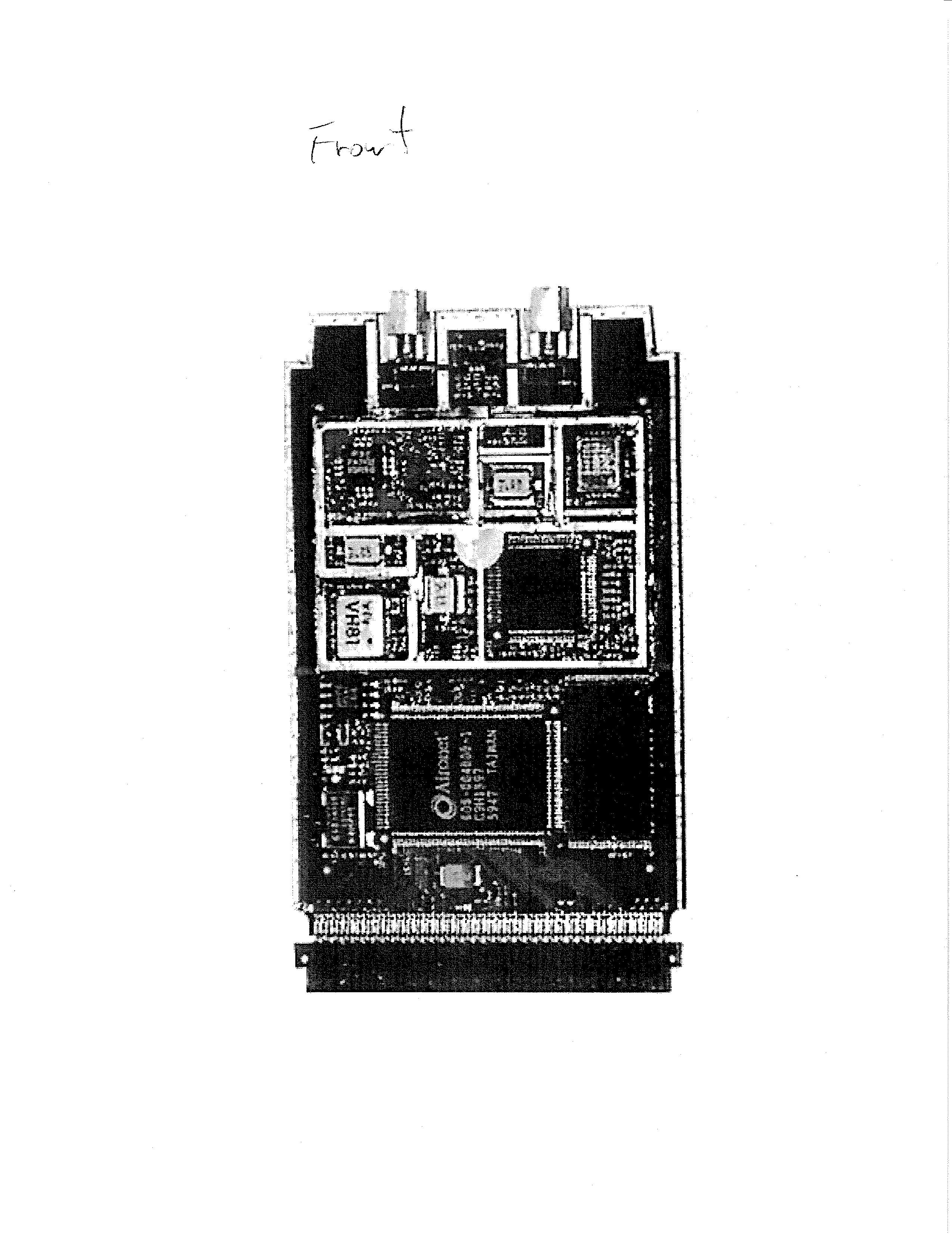
Click to zoom
Application Details
- Equipment Class
- DSS - Part 15 Spread Spectrum Transmitter
- Date of Grant
- Mar 04, 2003
- Application Purpose
- Original Equipment
- Date of Application
- Mar 04, 2003
- Equipment Note
- Wearable Wrist Computer
- Frequency Range
- 2412.00000000 - 2462.00000000
- Company
- Symbol Technologies Inc
- Country
- United States
Documents & Files
Document Text
Text extracted from the exhibit documents filed with the FCC. Open a document above to read the original.
Users Manual
WSS 1000 System WSS 1000 System 1999-2003 SYMBOL TECHNOLOGIES, INC. All rights reserved. Symbol reserves the right to make changes to any product to improve reliability, function, or design. Symbol does not assume any product liability arising out of, or in connection with, the application or use of any product, circuit, or application described herein. No license is granted, either expressly or by implication, estoppel, or otherwise under any patent right or patent, covering or relating to any combination, system, apparatus, machine, material, method, or process in which Symbol products might be used. An implied license exists only for equipment, circuits, and subsystems contained in Symbol products. Symbol and the Symbol logo are registered trademarks of Symbol Technologies, Inc. Other product names mentioned in this manual may be trademarks or registered trademarks of their respective companies and are hereby acknowledged. Symbol Technologies, Inc. One Symbol Plaza Holtsville, N.Y. 11742-1300 http://www.symbol.com Patents This product is covered by one or more of the following U.S. and foreign Patents: U.S. Patent No. 4,593,186; 4,603,262; 4,607,156; 4,652,750; 4,673,805; 4,736,095; 4,758,717; 4,760,248; 4,806,742; 4,816,660; 4,845,350; 4,896,026; 4,897,532; 4,923,281; 4,933,538; 4,992,717; 5,015,833; 5,017,765; 5,021,641; 5,029,183; 5,047,617; 5,103,461; 5,113,445; 5,130,520; 5,140,144; 5,142,550; 5,149,950; 5,157,687; 5,168,148; 5,168,149; 5,180,904; 5,216,232; 5,229,591; 5,230,088; 5,235,167; 5,243,655; 5,247,162; 5,250,791; 5,250,792; 5,260,553; 5,262,627; 5,262,628; 5,266,787; 5,278,398; 5,280,162; 5,280,163; 5,280,164; 5,280,498; 5,304,786; 5,304,788; 5,306,900; 5,324,924; 5,337,361; 5,367,151; 5,373,148; 5,378,882; 5,396,053; 5,396,055; 5,399,846; 5,408,081; 5,410,139; 5,410,140; 5,412,198; 5,418,812; 5,420,411; 5,436,440; 5,444,231; 5,449,891; 5,449,893; 5,468,949; 5,471,042; 5,478,998; 5,479,000; 5,479,002; 5,479,441; 5,504,322; 5,519,577; 5,528,621; 5,532,469; 5,543,610; 5,545,889; 5,552,592; 5,557,093; 5,578,810; 5,581,070; 5,589,679; 5,589,680; 5,608,202; 5,612,531; 5,619,028; 5,627,359; 5,637,852; 5,664,229; 5,668,803; 5,675,139; 5,693,929; 5,698,835; 5,705,800; 5,714,746; 5,723,851; 5,734,152; 5,734,153; 5,742,043; 5,745,794; 5,754,587; 5,762,516; 5,763,863; 5,767,500; 5,789,728; 5,789,731; 5,808,287; 5,811,785; 5,811,787; 5,815,811; 5,821,519; 5,821,520; 5,823,812; 5,828,050; 5,848,064; 5,850,078; 5,861,615; 5,874,720; 5,875,415; 5,900,617; 5,902,989; 5,907,146; 5,912,450; 5,914,478; 5,917,173; 5,920,059; 5,923,025; 5,929,420; 5,945,658; 5,945,659; 5,946,194; 5,959,285; 6,002,918; 6,021,947; 6,029,894; 6,031,830; 6,036,098; 6,047,892; 6,050,491; 6,053,413; 6,056,200; 6,065,678; 6,067,297; 6,082,621; 6,084,528; 6,088,482; 6,092,725; 6,101,483; 6,102,293; 6,104,620; 6,114,712; 6,115,678; 6,119,944; 6,123,265; 6,131,814; 6,138,180; 6,142,379; 6,172,478; 6,176,428; 6,178,426; 6,186,400; 6,188,681; 6,209,788; 6,209,789; 6,216,951; 6,220,514; 6,243,447; 6,244,513; 6,247,647; 6,308,061; 6,250,551; 6,295,031; 6,308,061; 6,308,892; 6,321,990; 6,328,213; 6,330,244; 6,336,587; 6,340,114; 6,340,115; 6,340,119; 6,348,773; 6,380,949; 6,394,355; D305,885; D341,584; D344,501; D359,483; D362,453; D363,700; D363,918; D370,478; D383,124; D391,250; D405,077; D406,581; D414,171; D414,172; D418,500; D419,548; D423,468; D424,035; D430,158; D430,159; D431,562; D436,104. Invention No. 55,358; 62,539; 69,060; 69,187, NI-068564 (Taiwan); No. 1,601,796; 1,907,875; 1,955,269 (Japan); European Patent 367,299; 414,281; 367,300; 367,298; UK 2,072,832; France 81/ 03938; Italy 1,138,713 rev. 06/02 Quick Reference 1 Introduction The WSS 1000 is a wearable data entry system consisting of a laser bar code scanner, usually worn on the operator’s fingers or back of hand, and a wrist computer (WWC 1000) worn on the operator’s forearm. The detachable components work equally well for right- and left-handed individuals. Detachable personal mounts allow multiple operators to share both scanner and wrist computer without having to use the same mount. About This Guide This guide presents information on system components, assembling the WWC 1000, battery installation and charging, attaching the system, using the keyboard, and disassembly for use by others. For wearable scanner information, refer to the WSS 1000 Product Reference Guide, or the Quick Reference Guide provided with your scanner. 2 WSS 1000 System Parts of the WSS 1000 System Keyboard Display Speaker Battery Latch Power Switch Battery Charging Contacts Lithium-Ion Battery WWC 1000 Top WWC 1000 (Wrist Computer) Front Adjustable Straps Snap-On Bar WWC 1000 Wrist Mount Quick Reference 3 Scanners for the WSS 1000 System SRS-1 RS-1 WS 1200 4 WSS 1000 System Installing and Charging the Battery The wrist computer and scanner are powered by a Lithium-Ion battery pack. The pack provides power for a typical 8-hour shift. Note:Before using the wrist computer, install and fully charge the Lithium-Ion battery pack. To install the battery pack in the WWC 1000: 1. Insert the battery pack, base first, in the battery compartment. 2. Line up the pack’s locking mechanism with the notch in the battery compartment wall by sliding the battery latch, and press the pack into place. 3. Release the battery latch to lock in place. Battery Latch Notch Battery Compartment Battery Pack Base Quick Reference 5 Charging the Battery in WWC 1000 To charge the Lithium-Ion battery in the WWC 1000: 1. Place the WWC 1000 in the cradle as shown be- low: 2. The cradle’s CHARGING light illuminates (RED) if the WWC 1000 is properly seated and the bat- tery is charging. 3. The battery requires approximately 2 hours to charge fully. The CHARGING light changes to GREEN when the battery is fully charged. 4. To remove the WWC 1000 from the cradle, tilt the WWC 1000 upward and pull out. For more information on the CS 1000 Cradle, re- fer to the CS 1000 Single-Slot Cradle QRG, p/n 70-16237-xx, or the …
Text truncated - open the document above for the full version.
Cover Letter(s)
Cisco Systems, Inc. 320 Springside Drive Akron, Ohio 44333 Phone: 330 664-7900 Fax: 330-664-7922 http://www.cisco.com Phone: (330) 664-7362 Fax: (330) 664-7301 E-Mail: [email protected] February 11, 2003 BABT 34 Molesey Road Walton on Thames Surrey KT12 4RQ Re: Symbol WSS-107C To Whom It May Concern: The following information is to be held confidential pursuant to 47 CFR Part 0 §0.457 and Section 552(b)(4) of the Freedom of Information Act, because the information provided is proprietary and contains trade secrets. If made public, the information might be used to the disadvantage of the Cisco Systems, Inc. in the market place. In addition, this information is to be withheld from the applicant, Symbol Technologies, Inc., as well. Bill of Material Block Diagram Schematic Diagrams Technical Description Best Regards, Jim Nicholson EMC Compliance Engineer
External Photos
Exhibit 3 External Photos Please see test report OR610739-2
ID Label/Location Info
NOTES: 1. SCRIPT FILE (S) TO BE CREATED BY MANUFACTURING AND MUST MATCH THIS DOCUMENT EXACTLY. 2. LABEL STOCK P/N IS SUBJECT TO CHANGE. CHECK BOM FOR ACTUAL P ART NUMBER. 3. IN ALL CASES "X's......" REPRESENT VARIABLE FIELDS IN SCRIPT FILE. ACTUAL NUMBER OF CHARACTERS MAY V ARY. 4. IN THE CASE OF MULTIPLE APPROVALS THE ID NUMBER AND TYPE NUMBERS APPEAR IN SAME ORDER. 5. PART NUMBER MAY OR MAY NOT HAVE DASH NUMBER BEFORE COUNTRY CODE. SEE BOM FOR EXACT MODEL NAME. 6. MONTH AND YEAR IF REQUIRED TO BE SHOWN . (IE: NOVEMBER, 2001) 7. COUNTRY OF ORIGIN REQUIRED. 8. CREATE VARIABLE FIELD FOR PLANT CODE. PROD FAM: SATURN WEARABLE, CISCO AIR-LMC352 RADIO DESCRIPTION: LBL:LCD, WWC107C OR WSS107C- WW CTRY CODE: WW COUNTRY: US, CANADA, SEE 21-40866-XX FOR LIST OF COUNTRIES SN POOL: STANDARD LBL STOCK PN: 63-32254-01 *SEE NOTE 2 LBL SCRIPT : 6104901B *SEE NOTE 1 CC1: M233 XXXX SEE NOTE 7 AND 8 MADE IN XXXXXX 69-61049-01B EC: 16818 SEE NOTE 5 MAY CALL OUT WWC107C OR WSS107C P/N: WXX107C-XXXX-WW (S)S/N A000004 BAR CODE SYMBOL TECHNOLOGIES, INC HOLTSVILLE N.Y. 1 1742 THIS DEVICE CONTAINS AN APPROVED RLAN MODULE THIS CLASS B DIGITAL APPARATUS COMPLIES WITH CANADIAN ICES-003. CET APPAREIL NUMÉRIQUE DE LA CLASSE B EST CONFORME À LA NORME NMB-003 DU CANADA. 0650 F C C I D : H 9 P W W C 1 0 7 C I C : 1 5 4 9 D - W W C 1 0 7 C T Y P E : L M C 3 5 2 F R E Q : 2 . 4 0 0 - 2 . 4 8 3 5 G H z
ID Label/Location Info
Exhibit 1: Label The placement of the label is shown on page 12 of test report OR610739/2 Issue 2. There is insufficient space for the statement required in Part 15.19 (a) (3) . This is included with the regulatory information in the QRG user guide.
Internal Photos
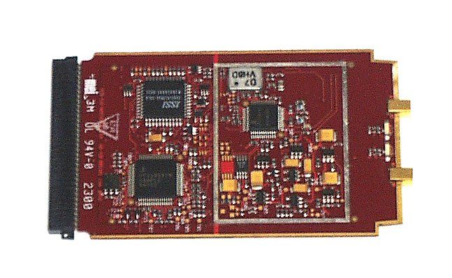
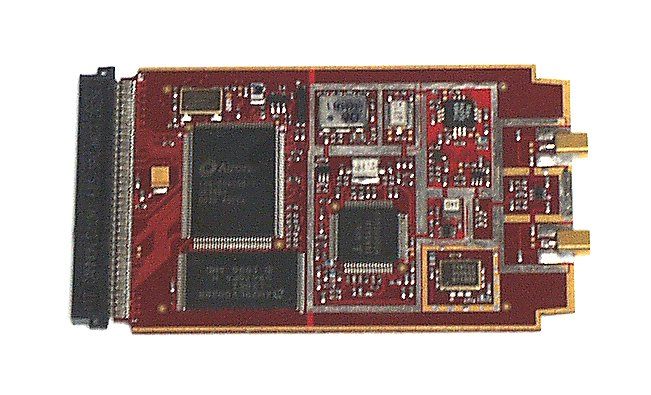
Exhibit 9 Internal Photos Please see test report OR610739-2
RF Exposure Info
TEST REPORT In support of the Application for Grant of Equipment Authorisation of the WWC-107C Wearable Wrist Computer FCC ID: H9PWSS107CMarch 2003 TUV Product Service Ltd. Segensworth Road, Titchfield Fareham, Hampshire, United Kingdom, PO15 5RH Tel: +44(0)1329 443300, Fax: +44(0)1329 443331 www.tuvps.co.uk Report Number WS610739 - Rev 1Page 1 of 28 REPORT ON:Specific Absorption Rate testing of the WWC-107C Wearable Wrist Computer Report No: WS601739 – Rev 1 FCC ID:H9PWWC107C PREPARED FOR: Symbol Technologies Symbol Place Winnersh Triangle Berkshire England RG41 5TP ATTESTATION:The wireless portable devices described within this report have been shown to be capable of compliance for localised specific absorption rate (SAR) for Occupational/Controlled Exposure Limits as defined in Supplement C (Edition 01-01) to OET Bulletin 65 (Edition 97-01) of 8.0 W/kg. The devices were tested in accordance with the measurement procedures specified in Supplement C (Edition 01-01) to OET Bulletin 65 (Edition 97-01) and IEEE1528-200x (Draft April 2002). I attest to the accuracy of data. All measurements reported herein were performed by me or were made under my supervision and are correct to the best of my knowledge and belief. I assume full responsibility for the completeness of these measurements. A. Miller SAR Test Engineer APPROVED BY: T Pither Quality Manager DATED:05 th March 2003 DISTRIBUTION:Symbol TechnologiesCopy No: 1 Symbol Technologies (CD ROM).Copy No(s): 2 BABT Copy No.: 3 Copy No.: 2 Note: The test results reported herein relate only to the item tested as identified above and on the Status Page. Report 610739 Re-issued to typographical errors on page 8 FCC ID: H9PWWC107C Report Number WS610739 - Rev 1Page 2 of 28 CONTENTS EXECUTIVE SUMMARY3 1.1Status4 1.2Summary5 1.3Test Result Summary6 TEST DETAILS7 2.1Test Equipment8 2.2Test Software8 2.3Dielectric Properties of Simulant Liquids9 2.4Test Conditions9 2.5Measurement Uncertainty10 2.6SAR Measuring System11 Probe and Amplifier Specification Probe Calibration SAR Measurement Procedure 2.7Test Positions16 2.8SAR Distributions (Area Scans – 2D)17 2.9Test Positional Photographs23 2.10Record Photographs24 2.11Manufacturer’s Label Drawing27 For copyright details see page 28 of 28. FCC ID: H9PWWC107C Report Number WS610739 - Rev 1Page 3 of 28 EXECUTIVE SUMMARY Specific Absorption Rate Testing of the WWC-107C Wearable Wrist Computer PROJECT MANAGER: A. BISHOP FCC ID: H9PWWC107C Report Number WS610739 - Rev 1Page 4 of 28 1.1STATUS MANUFACTURING DESCRIPTIONWWC-107C Wearable Wrist Computer STATUS OF TESTSpecific Absorption Rate Testing APPLICANTSymbol Technologies CLASSIFICATIONDSS (Direct Spread Spectrum Device) MANUFACTURERSymbol Technologies TYPE OR MODEL NUMBERWWC 107C HARDWARE VERSIONRev 2 SOFTWARE VERSIONNBASNGAA, Rev A SERIAL NUMBERMXA16552 BATTERY MANUFACTURERSYMBOL TYPE OR MODEL NUMBER20-16228-09 Rev B 3.6V 1450mAh Li-ion TEST SPECIFICATIONS: Federal Communications Commission, Code of Federal Regulations, Title 47 (CFR47), Vol. 1, Chapter 1, Part 2 (§2.1091 and §2.1093). Federal Communications Commission (FCC) OET Bulletin 65c, Edition 01-01, Evaluating Compliance with FCC Guidelines for Human Exposure to Radiofrequency Electromagnetic Fields – Additional Information for Evaluating Compliance of Mobile and Portable Devices with FCC Limits for Human Exposure to Radiofrequency Emissions REFERENCES: IEEE 1528 –200X: DRAFT Recommended Practice for Determining the Peak Spatial-Average Specific Absorption Rate (SAR) in the Human Body Due to Wireless Communications Devices: Experimental Techniques CENELEC EN 50360: July 2001, Product Standard to demonstrate the compliance of mobile phones with the basic restrictions related to human exposure electromagnetic (300 MHz - 3 GHz). CENELEC EN 50361: July 2001, Basic standard for the measurement of Specific Absorption Rate related to human exposure to electromagnetic fields from mobile phones (300 MHz - 3 GHz). Council Recommendations 1999/519/EC on the limitations of exposure of the general public to electromagnetic fields (0 Hz - 3 GHz) annex II. BABT REGISTRATION NUMBER:WS610739. RECEIPT OF TEST SAMPLES:19 th February 2003. START OF TEST:20 th February 2003. FINISH OF TEST:21 st February 2003. FCC ID: H9PWWC107C Report Number WS610739 - Rev 1Page 5 of 28 1.2SUMMARY The WWC-107C Wearable Wrist Computer supplied for Specific Absorption Rate (SAR) testing to the requirements of Supplement C (Edition 01-01) to OET Bulletin 65 (Edition 97-01) is a Body worn Direct Spread Spectrum Device. The equipment incorporates a PCMCIA radio card Model AIR-LMC352, manufactured by Cisco Systems Inc. FCC ID: LDK102040. It is designed to operate within the 2.4GHz band (2.4GHz to 2.4835GHz). It was found to be compliant with requirements for Occupational/Controlled Exposure for Mobile/Portable devices. The Partial- Body SAR limit of 1g volume averaged SAR is stated as 8.0W/kg. SAR testing was performed using a Flat Phantom dimensions 220mmx200mmx150mm and with a sidewall thickness of 2.0mm. The phantom was filled to a depth of 150mm with 2450MHz Body simulant liquid. The dielectric properties were in accordance with the requirements for the dielectric properties specified in Supplement C (Edition 01-01) to OET Bulletin 65 (Edition 97-01). The WWC-107C Wearable Wrist Computer had an integral antenna. The WWC-107C Wearable Wrist Computer was set to maximum transmit power using the onboard test software, with the following configurations: - F 2400 FF F XXXX (XXXX Frequency setting in MHz = 2412; 2442; 2462 & 2472) P B7 (B7 Max Power setting) A 0 (Antenna Port) TT 1 3 (Transmission Test: 1 modulation = CW and 3 Baud Speed = 11Mbs) The testing was performed with a fully charged battery for the positions for which higher SAR levels were recorded. No accessories were supplied with WWC-107C Wearable Wrist Computer. Note: for Body worn operation, the WWC-107C Wearable Wrist Computer has been tested and meets the FCC RF exposure guid…
Text truncated - open the document above for the full version.
RF Exposure Info
IMMERSIBLE SAR PROBE CALIBRATION REPORT Part Number: IXP – 050 S/N 0117 10 th October 2002 Indexsar Limited Oakfield House Cudworth Lane Newdigate Surrey RH5 5DR Tel: +44 (0) 1306 631 233 Fax: +44 (0) 1306 631 834 e-mail: [email protected] 2 INTRODUCTION This Report presents measured calibration data for a particular Indexsar SAR probe (S/N 0117) and describes the procedures used for characterisation and calibration. Indexsar probes are characterised using procedures that, where applicable, follow the recommendations of CENELEC [1] and IEEE [2] standards. The procedures incorporate techniques for probe linearisation, isotropy assessment and determination of liquid factors (conversion factors). Calibrations are determined by comparing probe readings with analytical computations in canonical test geometries (waveguides) using normalised power inputs. Each step of the calibration procedure and the equipment used is described in the sections below. CALIBRATION PROCEDURE 1. Equipment Used For the first part of the characterisation procedure, the probe is placed in an isotropy measurement jig as pictured in Figure 1. In this position the probe can be rotated about its axis by a non-metallic belt driven by a stepper motor. The probe is attached via its amplifier and an optical cable to a PC. A schematic representation of the test geometry is illustrated in Figure 2. A balanced dipole (900 MHz) is inserted horizontally into the bracket attached to a second belt (Figure 1). The dipole can also be rotated about its axis. A cable connects the dipole to a signal generator, via a directional coupler and power meter. The signal generator feeds an RF amplifier at constant power, the output of which is monitored using the power meter. The probe is positioned so that its sensors line up with the rotation center of the source dipole. By recording output voltage measurements of each channel as both the probe and the dipole are rotated, data are obtained from which the spherical isotropy of the probe can be optimised and its magnitude determined. The calibration process requires E-field measurements to be taken in air, in 900 MHz simulated brain liquid and at other frequencies/liquids as appropriate. 2. Linearising probe output The probe channel output signals are linearised in the manner set out in Refs [1] and [2]. The following equation is utilized for each channel: U lin = U o/p + U o/p 2 / DCP (1) where U lin is the linearised signal, U o/p is the raw output signal in voltage units and DCP is the diode compression potential in similar voltage units. DCP is determined from fitting equation (1) to measurements of U lin versus source feed power over the full dynamic range of the probe. The DCP is a characteristic of 3 the schottky diodes used as the sensors. For the IXP-050 probes with CW signals the DCP values are typically 0.10V (or 20 in the voltage units used by Indexsar software, which are V*200). 3. Selecting channel sensitivity factors to optimise isotropic response The basic measurements obtained using the calibration jig (Fig 1) represent the output from each diode sensor as a function of the presentation angle of the source (probe and dipole rotation angles). The directionality of the orthogonally-arranged sensors can be checked by analysing the data using dedicated Indexsar software, which displays the data in 3D format as in Figure 3. The left-hand side of this diagram shows the individual channel outputs after linearisation (see above). The program uses these data to balance the channel outputs and then applies an optimisation process, which makes fine adjustments to the channel factors for optimum isotropic response. The next stage of the process is to calibrate the Indexsar probe to a W&G EMR300 E- field meter in air. The principal reasons for this are to obtain conversion factors applicable should the probe be used in air and to provide an overall measure of the probe sensitivity. A multiplier is applied to factors to bring the magnitudes of the average E-field measurements as close as possible to those of the W&G probe. The following equation is used (where linearised output voltages are in units of V*200): E air 2 (V/m) = U linx * Air Factor x + U liny * Air Factor y + U linz * Air Factor z (2) It should be noted that the air factors are not separately used for normal SAR testing. The IXP-050 probes are optimised for use in tissue-simulating liquids and do not behave isotropically in air. 4. 900 MHz Liquid Calibration Conversion factors for use when the probes are immersed in tissue-simulant liquids at 900 MHz are determined either using a waveguide or by comparison to a reference probe that has been calibrated by NPL. Waveguide procedures are described later. The summary sheet indicates the method used for the probe S/N 0117. The conversion factor, referred to as the ‘liquid factor’ is also applied to the measurements of each channel. The following equation is used (where output voltages are in units of V*200): E liq 2 (V/m) = U linx * Air Factor x * Liq Factor x + U liny * Air Factor y * Liq Factor y + U linz * Air Factor z * Liq Factor z (3) A 3D representation of the spherical isotropy for probe S/N 0117 using these factors is shown in Figure 3. 4 The rotational isotropy can also determined from the calibration jig measurements and is reported as the 900MHz isotropy in the summary table. Note that waveguide measurements can also be used to determine rotational isotropy (Fig. 5). The design of the cells used for determining probe conversion factors are waveguide cells is shown in Figure 4. The cells consist of a coax to waveguide transition and an open-ended section of waveguide containing a dielectric separator. Each waveguide cell stands in the upright positition and is filled with liquid within 10 mm of the open end. The seperator provides a liquid seal and is designed for a good electrical transition from air filled guide to liquid filled guide. The choice of cell depends on …
Text truncated - open the document above for the full version.
Test Report
REPORT ON FCC Part 15 Testing of a WWC107C Wearable Wrist Computer FCC ID: H9PWWC107C Report No OR610739/2 Issue 2February 2003 TUV Product Service Ltd, Segensworth Road, Titchfield Fareham, Hampshire, United Kingdom, PO15 5RH Tel: +44(0)1329 443459, Fax: +44(0)1329 443331 www.tuvps.co.uk Report No OR610739/2 Issue 2Page 1 of 25 REPORT ONFCC Part 15C Testing of a WWC107C Wearable Wrist Computer FCC ID: H9PWWC107C Report No OR610739/2 Issue 2 February 2003 PREPARED FORSymbol Technologies Symbol Place Winnersh Triangle Berkshire RG41 5TP APPROVED BY K W Adsetts UKAS EMC Signatory DATED26 February 2003 DISTRIBUTIONSymbol TechnologiesCopy 1 Copy No. 2 (CD) TÜV Product ServiceCopy 3 Copy No Note: This report is re-issued to correct a typographical error on page 7 Total No of Pages 25 Report No OR610739/2 Issue 2FCC ID:H9PWWC107C Page 2 of 25 Table of Contents Page No STATUS ................................................................................................................................................3 TEST RATIONALE................................................................................................................................4 SYSTEM CONFIGURATION ............................................................................................................... 5 TEST SETUP PHOTOGRAPH .............................................................................................................6 EQUIPMENT INFORMATION .............................................................................................................7 RADIATED ELECTRIC FIELD EMISSIONS.........................................................................................8 MAXIMUM PEAK OUTPUT POWER................................................................................................... 10 PHOTOGRAPHS OF EQUIPMENT...................................................................................................... 11 MANUFACTURER’S LABEL DRAWING .............................................................................................. 22 FCC SITE COMPLIANCE LETTER ......................................................................................................23 SYSTEM MEASUREMENT UNCERTAINTY ....................................................................................... 24 COPYRIGHT STATEMENT .................................................................................................................. 25 Report No OR610739/2 Issue 2FCC ID:H9PWWC107C Page 3 of 25 STATUS OBJECTIVETo undertake measurements to determine the Equipment Under Test's (EUT's) compliance with the specification. MANUFACTURING DESCRIPTIONWearable Wrist Computer APPLICANTSymbol Techologies Inc One Symbol Plaza Holtsville MANUFACTURERS MODEL NUMBERWWC107C SERIAL NUMBERMXA16552 TEST SPECIFICATION NUMBERFCC Part 15 Subpart C REGISTRATION NUMBEROR610739 QUANTITY OF ITEMS TESTEDOne SECURITY CLASSIFICATION OF EUTUnclassified INCOMING RELEASEDeclaration of Build Status SERIAL NUMBEROR610739 DATE DISPOSALHeld pending disposal REFERENCE NUMBERN/A DATEN/A ORDER NUMBEREMEA 12600 DATE29 January 2003 START OF TEST10 February 2003 FINISH OF TEST13 February 2003 TEST ENGINEERSA R Hubbard A Blagg RELATED DOCUMENTSANSI C63.4 2001. Methods of Measurement of Radio-Noise Emissions from Low-Voltage Electrical and Electronic Equipment in the Range of 9 kHz to 40 GHz. Report No OR610739/2 Issue 2FCC ID:H9PWWC107C Page 4 of 25 TEST RATIONALE The equipment incorporates a PCMCIA radio card Model AIR-LMC352, manufactured by Cisco Systems Inc. FCC ID: LDK102040. Testing was carried out in accordance with the customer’s requirements. Section 3 of the report details testing carried out in accordance with: • FCC: Part 15.247(c), Radiated Electric Field Emissions • FCC: Part 15.247(b), Maximum Peak Output Power Report No OR610739/2 Issue 2FCC ID:H9PWWC107C Page 5 of 25 SYSTEM CONFIGURATION DURING EMC TESTING The WWC107C was set-up simulating a typical user installation on the Alternative Open Field Test Site identified on page 23, and tested in accordance with the specification. The EUT was set to transmit continuously on maximum output power during all testing. The EUT was powered from its integral battery, which was replaced with a freshly charged battery as required during the testing. Report No OR610739/2 Issue 2FCC ID:H9PWWC107C Page 6 of 25 TEST SETUP PHOTOGRAPH The photograph below shows the EUT configuration during Radiated Emission testing. Report No OR610739/2 Issue 2FCC ID:H9PWWC107C Page 7 of 25 EQUIPMENT INFORMATION Equipment under Test (EUT): Equipment: Wrist Worn Computer Manufacturer: Symbol Technologies Type No: WWC107C Serial No: MXA16552 Build Status: Rev 2 Software Status: NBASNGAA, Rev A Instrumentation used for Emission Testing: InstrumentManufacturerType NoEMC NoCal to EMI ReceiverHewlett Packard8542E228613 Dec 03 Bilog AntennaChaseCBL6143286011 Apr 03 Turntable & ControllerHD GmbHHD 0502528TU Antenna MastEmco10512182TU Antenna Mast ControllerEmco10502090TU Low Noise Amplifier (1-8GHz)MiteqAMF-3D-001080-18-13P2457TU Spectrum AnalyserHewlett Packard8562A142710 Jan 04 HornEMCO3115239729 Jun 03 Signal GeneratorRohde & SchwarzSMR40276823 Feb 03 Low Noise Amplifier (8-18GHz)AvantekAWT 180361081TU Low Noise Amplifier (18-26GHz)AvantekAMT-26177-332072TU HornFMI2024/201396TU Waveguide to Coax AdaptorFMI2093SF40S/N 595TU 4GHz High Pass FilterRLC ElectronicsF-100-4000-5-RINV 04468 TU Instrumentation used for Maximum Power measurements Spectrum AnalyzerRohde and ShwarzFSEM403416 Dec 03 Signal GeneratorHewlett PackardESG 4000A370921 Jan 04 DRG AntennaEMCO3115354929 Jun 03 Substitution DRG AntennaEMCO3115377720 Jan 04 CableReynolds Industries269-0088-3000CS0567TU CableRosenbergerFA210B-1-070MCS0535TU TU - Traceability Unscheduled Report No OR610739/2 Issue 2FCC ID:H9PWWC107C Page 8 of 25 RADIATED ELECTRIC FIELD EMISSIONS TEST PROCEDURE Testing was carried out to the requirements of FCC Part 15 Subpart C, Section …
Text truncated - open the document above for the full version.
Test Report
FCC ID: LDK102040 MFA p0040008, d0050047 Date: May 31, 2000 Federal Communications Commission Via: Electronic Filing Attention: Authorization & Evaluation Division Applicant: Cisco Systems Inc Equipment: AIR-LMC350 FCC ID: LDK102040 FCC Rules: 15.247 and Confidentiality Gentlemen: On behalf of the Applicant, enclosed please find Application Form 731, Engineering Test Report and all pertinent documentation, the whole for approval of the referenced equipment as shown. Filing fees are attached. We trust the same is in order. Should you need any further information, kindly contact the writer who is authorized to act as agent. Sincerely yours, Morton Flom, P. Eng. enclosure(s) cc: Applicant MF/cvr FCC ID: LDK102040 MFA p0040008, d0050047 LIST OF EXHIBITS (FCCCERTIFICATION(TRANSMITTERS) - REVISED 9/28/98) APPLICANT: Cisco Systems Inc FCC ID: LDK102040 BY APPLICANT: 1. LETTER OF AUTHORIZATION 2. IDENTIFICATION DRAWINGS ID LABEL LOCATION INFO ATTESTATION STATEMENT(S) LOCATION OF COMPLIANCE STATEMENT 3. DOCUMENTATION: 2.1033(b) (3) USER MANUAL(S) (4) OPERATIONAL DESCRIPTION (5) BLOCK DIAGRAM (5) SCHEMATIC DIAGRAM (7) EXTERNAL PHOTOGRAPHS INTERNAL PHOTOGRAPHS PARTS LIST ACTIVE DEVICES 4. DRAFT SPECIFICATION INFORMATION 5. PARTS LIST/TUNE UP INFO BY M.F.A. INC. A. TESTIMONIAL & STATEMENT OF CERTIFICATION B. STATEMENT OF QUALIFICATIONS FCC ID: LDK102040 MFA p0040008, d0050047 Sub-part 2.1033(c): EQUIPMENT IDENTIFICATION FCC ID: LDK102040 NAMEPLATE DRAWING ATTACHED, EXHIBIT 1. LOCATION AS PER LABEL DRAWING(S) DATE OF REPORT May 31, 2000 SUPERVISED BY: Morton Flom, P. Eng. FCC ID: LDK102040 MFA p0040008, d0050047 THE APPLICANT HAS BEEN CAUTIONED AS TO THE FOLLOWING: 15.21 INFORMATION TO USER. The users manual or instruction manual for an intentional radiator shall caution the user that changes or modifications not expressly approved by the party responsible for compliance could void the user's authority to operate the equipment. 15.27(a) SPECIAL ACCESSORIES. Equipment marketed to a consumer must be capable of complying with the necessary regulations in the configuration in which the equipment is marketed. Where special accessories, such as shielded cables and/or special connectors are required to enable an unintentional or intentional radiator to comply with the emission limits in this part, the equipment must be marketed with, i.e. shipped and sold with, those special accessories. However, in lieu of shipping or packaging the special accessories with the unintentional or intentional radiator, the responsible party may employ other methods of ensuring that the special accessories are provided to the consumer, without additional charge. Information detailing any alternative method used to supply the special accessories for a grant of equipment authorization or retained in the verification records, as appropriate. The party responsible for the equipment, as detailed in § 2.909 of this chapter, shall ensure that these special accessories are provided with the equipment. The instruction manual for such devices shall include appropriate instructions on the first page of text concerned with the installation of the device that these special accessories must be used with the device. It is the responsibility of the user to use the needed special accessories supplied with the equipment. FCC ID: LDK102040 MFA p0040008, d0050047 TABLE OF CONTENT…
Text truncated - open the document above for the full version.
Contact Information
Applicant
Qianlin Zhou(Regulatory Specialist)
Test Firm
TUV SUD Product ServiceJensen Adams
Technical Specifications
| # | Rule Parts | Frequency Range | Power Output | Emission |
|---|---|---|---|---|
| 1 | 15C | 2.41 GHz - 2.46 GHz | 100.00 mW | 11M0F1D |
Other Applications from Symbol Technologies Inc

H9PCCHUB1
Jun 30, 2015Customer Concierge
Equipment Class
NII - Unlicensed National Information Infrastructure TX
H9PAP7562
May 10, 2015802.11 abgn/ac Access Point
Equipment Class
DTS - Digital Transmission System
H9PTC75AH
Mar 26, 2015Touch Computer
Equipment Class
NII - Unlicensed National Information Infrastructure TX
H9PRA1202
Sep 24, 2014UHF Narrowband Radio Module
Equipment Class
TNB - Licensed Non-Broadcast Station Transmitter
H9PEMG101
Aug 26, 2014802.15.4 Gateway
Equipment Class
DTS - Digital Transmission System