HHC-115A00HAI Omni-Bus RF Transceiver
Home Automation Inc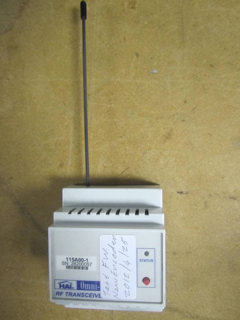
Click to zoom
Application Details
- Equipment Class
- DSR - Part 15 Remote Control/Security Device Transceiver
- Date of Grant
- Sep 26, 2012
- Application Purpose
- Original Equipment
- Date of Application
- Sep 26, 2012
- Equipment Note
- HAI Omni-Bus RF Transceiver
- Frequency Range
- 433.92000000 - 433.92000000
- Company
- Home Automation Inc
- Country
- United States
Documents & Files
Document Text
Text extracted from the exhibit documents filed with the FCC. Open a document above to read the original.
Users Manual
© 2012 Home Automation, Inc. www.homeauto.com Document: 115I00-1, Rev2.0 September 2012 BUS NETWORK CABLE (CAT5 UTP) TO NEXT DEVICE FROM PREVIOUS DEVICE Antenna HAI Omni-Bus RF Transceiver Model 115A00-1 Installation Instructions and User’s Guide Specifications o Bus side supply voltage: 15-24VDC (via bus network cable) o Bus side supply current: 50mA maximum o Ambient Temperature: 0 – 40 ºC (32 – 104 ºF) o Ingress Protection: IP20 o Dimensions: 70mm (width) x 58mm (height) x 86mm o Memory capacity (linked devices): 56 o RF Frequency: 433.92MHz o Transmit Range: Up to 30m (98 feet) Wiring Diagram Installation o Do not connect any mains wiring to the unit. The Transceiver connects directly to the HAI Omni-Bus network cable via 2 RJ45 connectors. o The Transceiver is designed for indoor use only. For outdoor use a suitable enclosure should be used. o Screw the supplied metal antenna into the top of the unit. o Do not bend or modify the antenna in any way. o For optimal performance the antenna should be kept clear of any metal objects or surfaces. o Do not install the Transceiver within 1m range of other Bus Transceivers or 433MHz receiving units. o Choose a location free of water, humidity, direct sunlight or heavy dust. o A safe isolation distance should be kept between all mains wiring and the Bus network cable o See the HAI Omni-Bus Network Installation Guide for more information on the Bus network wiring Setup o To link a device to the RF Transceiver without using the HAI OMNIBUS installation software: o Enter program mode by pressing and holding the button on the Transceiver until the Status LED starts flashing amber o For a Bus Wallswitch, press and hold the wallswitch button until the wallswitch LED flashes rapidly o For a RF Remote Control, execute an ADD command from the remote control (see remote control user instructions) o Press and release the Transceiver button to exit program mode o Setup from OMNIBUS installation software: o Enter the Transceiver setup by double clicking on the device in the device list after a LIST DEVICES o Use the Setup Tab to change the following device parameters: o Receive o Enable: Check to enable the RF receiver function on the unit. Packets received from any Omni-Bus remote control (6 or 16 channel keyring, Wallmount remote) will be placed onto the Bus network for control of Bus output devices (Bus Dimmers, Power Switches and Relay Modules) o Select the appropriate radio button to receive either all Omni-Bus remote controls or only remote controls added to the Transceiver Link list o Transmit o Enable: Check to enable the RF transmit function on the unit. Commands received from any Bus input unit (Bus Wallswitch or Switch Interface) on the same Bus Network as the RF Transceiver will be retransmitted via RF for control of wireless Omni-Bus devices. Select the appropriate radio button to transmit either all Omni-Bus Wallswitch buttons or only Wallswitch buttons added to the Transceiver Link list o Repeater Mode o When enabled, allows an Omni-Bus remote control packet received at one Transceiver, to be retransmitted at another Transceiver on the same Bus network. The receiving Transceiver must have its Receive function enabled for that remote control. The transmitting Transceiver must have its Repeater Mode enabled. Click on the Repeater Setup button to change additional settings regarding the repeater functionality. o Use the Links Tab to link input devices (wall switches and remote controls) to the transceiver. Status LED o Constant Green: Normal operation o Off flash while Green: Omni-Bus RF Packet received o Red flash: Omni-Bus RF packet transmitted o Flashing amber: Program mode active FCC ID: HHC-115A00-1 IC: 1516A-115A001 This device complies with Part 15 of the FCC Rules. Operation is subject to the following two conditions: (1) This device may not cause harmful interference, and (2) this device must accept any interference received, including interference that may cause undesired operation. Caution: Changes or modifications not expressly approved by the party responsible for compliance could void the user's authority to operate the equipment.
Cover Letter(s)
® www.homeauto.com HAI 4330 Michoud Blvd. New Orleans, LA 70129 Phone: 800-229-7256 Fax: 504-253-2955 December 20, 2011 Attention: Application Examiner Re: Request for confidentiality Applicant: Home Automation, Inc. FCC ID: HHC-115A00-1 To whom it may concern, Permanent Confidentiality Request is hereby submitted by Home Automation, Inc. to withhold permanently from public review certain portions of the application for equipment certification for the referenced FCC identifiers. This request for confidentiality is made pursuant to 47 CFR 0.457(d) and 0.459 of the FCC Rules. In particular, the following sections of the application are to be kept permanently confidential: Schematics Detailed Block diagrams Detailed Operational/Functional Description Parts list Rationale for request for confidentiality: Home Automation, Inc. has invested considerable time and materials in research and development to produce the referenced product. Disclosure of the permanently confidential portions of this application to competitors would not only give them significant competitive advantages in developing similar products, but would also disclose successful implementation of unpublished, leading edge technology developed by us. If you have questions or need further information, please contact the undersigned. Sincerely, Ron Gumina VP, Product Development Home Automation, Inc.
ID Label/Location Info
HAI Model: 115A00-1 FCC ID: HHC-115A00-1 IC: 1516A-115A001 This device complies with part 15 of the FCC Rules. Operation is subject to the following two conditions: (1) This device may not cause harmful interference, and (2) this device must accept any interference received, including interference that may cause undesired operation.
Test Report
This report is for the exclusive use of Intertek's Client and is provided pursuant to the agreement between Intertek and its Client. Intertek's responsibility and liability are limited to the terms and conditions of the agreement. Intertek assumes no liability to any party, other than to the Client in accordance with the agreement, for any loss, expense or damage occasioned by the use of this report. Only the Client is authorized to permit copying or distribution of this report and then only in its entirety. Any use of the Intertek name or one of its marks for the sale or advertisement of the tested material, product or service must first be approved in writing by Intertek. The observations and test results in this report are relevant only to the sample tested. This report by itself does not imply that the material, product, or service is or has ever been under an Intertek certification program. EMC Report for Home Automation Inc on the 115A00-1 Page 1 of 21 TEST REPORT Report Number: 100468650DAL-005c Project Number: G100468650 Report Issue Date: 7/30/12 Product Designation: 433.92 MHz RF Transceiver Din Rail Model: 115A00-1 Standards: 47 CFR Part 15, Subpart C (15.231 - Periodic operation in the band 40.66-40.70 MHz and above 70 MHz) RSS-210, Issue 8, 2010 Tested by: Client: Intertek Testing Services NA, Inc. 1809 10 th St. Plano TX 75074 Home Automation Inc. 4330 Michoud Blvd New Orleans, LA 70129 Report prepared by Report reviewed by William Cullen EMC Team Lead Jeremy O. Pickens EMC Manager Intertek Report Number: 100468650DAL-005c Issued: 07/30/2012 EMC Report for Home Automation Inc. on the 115A00-1 Page 2 of 21 TABLE OF CONTENTS (OPTIONAL) 1 Introduction and Conclusion .............................................................................................................. 3 2 Test Summary ...................................................................................................................................... 3 3 Description of Equipment Under Test ............................................................................................... 4 4 System setup including cable interconnection details, support equipment and simplified block diagram ........................................................................................................................................................ 5 5 Duty Cycle Determination (FCC 15A - 15.35(c)) ................................................................................ 6 6 Radiated emissions (E-field) for low power intentional radiators................................................. 10 7 Bandwidth Requirements (FCC 15C - 15.231(c))............................................................................. 16 8 Conducted emissions on AC power lines ....................................................................................... 18 9 Restrictions (FCC 15C - 15.231(a)) ................................................................................................... 18 10 Revision History ................................................................................................................................... 21 Intertek Report Number: 100468650DAL-005c Issued: 07/30/2012 EMC Report for Home Automation Inc on the 115A00-1 Page 3 of 21 1 Introduction and Conclusion The tests indicated in section 2.0 were performed on the product constructed as described in section 3.0. The remaining test sections are the verbatim text from the actual data sheets used during the investigation. These test sections include the test name, the specified test Method, a list of the actual Test Equipment Used, documentation Photos, Results and raw Data. No additions, deviations, or exclusions have been made from the standard unless specifically noted. Based on the results of our investigation, we have concluded the product tested complies with the requirements of the standard indicated. The results obtained in this test report pertain only to the item tested. 2 Test Summary Section Test full name Test date Result 3 Description of Equipment Under Test 4 System setup including cable interconnection details, support equipment and simplified block diagram 5 Duty Cycle Determination (FCC 15A - 15.35(c)) 07/11/12 Pass 6 Radiated emissions (E-field) for low power intentional radiators 05/16/12 Pass 7 Bandwidth Requirements (FCC 15C - 15.231(c)) 07/11/12 Pass 8 Conducted Emissions testing is not required as EUT is battery powered. N/A N/A 9 Restrictions (FCC 15C - 15.231(a)) 05/16/12 Pass 10 10 Revision History --- --- Intertek Report Number: 100468650DAL-005c Issued: 07/30/2012 EMC Report for Home Automation Inc on the 115A00-1 Page 4 of 21 3 Description of Equipment Under Test Equipment Under Test Description Manufacturer Model Number Serial Number RF Transceiver Din Rail Home Automation Inc 115A00-1 28200057 Receive Date: 4/25/12 Received Condition: Good Type: Production Description of Equipment Under Test (provided by client) EUT is a Low Power Wireless transceiver that transmits a 433.92 MHz signal to the Omni-Bus Control system and allows a home owner to adjust various applications around their home (i.e. lights, security system, etc.) Transmitter Overview: FCC Identifier HHC-115A00-1 IC Identifier 1516A-115A001 Frequency Range 433.92MHz Modulation ASK - OOK Antenna type (15.203) Antenna professionally installed. Equipment Under Test Power Configuration Rated Voltage Rated Current Rated Frequency Number of Phases 24VDC N/A N/A N/A Operating modes of the EUT: No. Descriptions of EUT Exercising 1 For Radiated emissions testing, EUT was Transmitting continuously @ 433.9MHz. The EUT is mounted on a din rail and therefore has one orientation for testing purposes. 2 For Bandwidth testing, EUT was Transmitting @ 433.9MHz every 10 seconds. Intertek Report Number: 100468650DAL-005c Issued: 07/30/2012 EMC Report for Home Automation Inc on the 115A00-1 Page 5 of 21 4 System setup including cable interconnection details, support…
Text truncated - open the document above for the full version.
Test Setup Photos
Intertek Report Number: 100468650DAL-005c Issued: 07/30/2012 EMC Report for Home Automation Inc on the 115A00-1 Page 12 of 21 6.4 Setup Photographs: Test setup
Contact Information
Applicant
Brian A. Yokum(Chief Technology Officer)
Test Firm
Intertek Testing Services NA, Inc.Paul Coghill
Technical Specifications
| # | Rule Parts | Frequency Range | Power Output |
|---|---|---|---|
| 1 | 15.231 | 433.92 MHz - 433.92 MHz | - |
Other Applications from Home Automation Inc
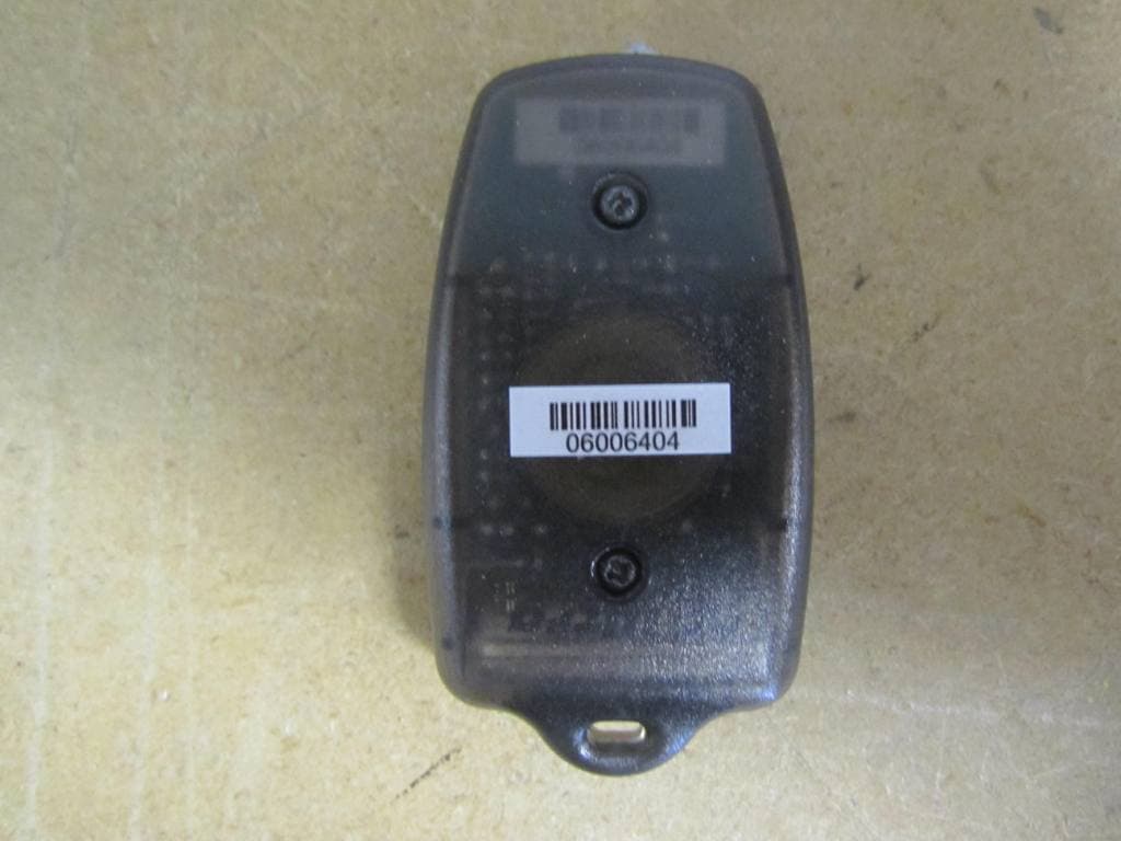
HHC-125A00
Sep 26, 2012HAI Omni-Bus Keyfob Remote Control
Equipment Class
DSR - Part 15 Remote Control/Security Device Transceiver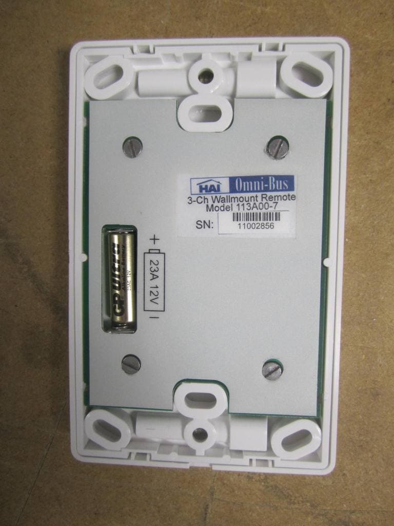
HHC-113A00
Sep 26, 2012HAI Omni-Bus Wireless Wall Switch
Equipment Class
DSR - Part 15 Remote Control/Security Device Transceiver
HHC-65A261
Dec 17, 2009Zigbee Module
Equipment Class
DTS - Digital Transmission System
HHCOMNISTAT-Z
Aug 26, 2007Z-Wave Thermostat
Equipment Class
DXX - Part 15 Low Power Communication Device Transmitter