HHOYC0072.4G/Wireless N USB Adapter
Shenzhen Yichen Technology Development Co., Ltd.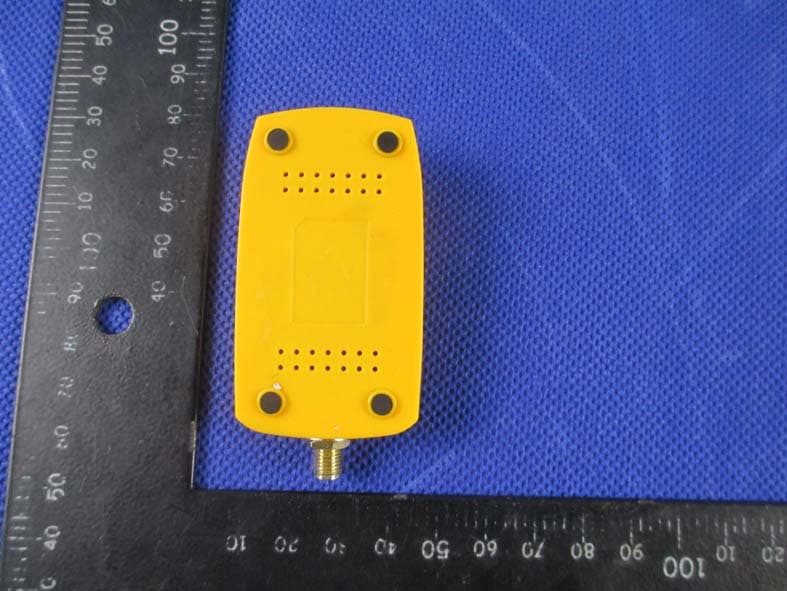
Click to zoom
Application Details
- Equipment Class
- DTS - Digital Transmission System
- Date of Grant
- Apr 17, 2013
- Application Purpose
- Original Equipment
- Date of Application
- Apr 17, 2013
- Equipment Note
- 2.4G/Wireless N USB Adapter
- Frequency Range
- 2412.00000000 - 2462.00000000
- Country
- China
Documents & Files
Document Text
Text extracted from the exhibit documents filed with the FCC. Open a document above to read the original.
Users Manual
2.4G/Wireless-N USB Adapter Quick Installation Guide 1. Hardware Installation 1.1 Hardware Installation for PCI Adapter 1) Turn off your desktop PC and disconnect the power. 2) Open your PC’s case and locate an available PCI slot on the motherboard.Remove the metal slot cover on the back Of the PC. Check with your computermanufacturer for instructions if needed. 3) Slide the PCI adapter into the PCI slot. Make sure that all of its pins are touching the slot’s contacts. Once the adapter is firmly in place, secure its fastening tab to your PC’s chassis with a mounting screw. Then, close your PC’s case. 4) Reconnect your PC’s power and power on your desktop PC 1.2 Hardware Installation for USB Adapter Connect USB adapter to the USB interface on your computer. 1.3 Hardware Installation for Cardbus Adapter 1) Locate an available CardBus slot on your notebook PC. 2) With the connector pin end facing the CardBus slot and the label facing up, slide the adapter into the CardBus slot until it locks in place. 3) The Status LED should flash when the adapter is installed correctly.. 2. Software Installation for Windows XP 1. When “Found New Hardware Wizard” is prompted, click Cancel, then insert the Resource CD into your CD-ROM drive. Choose Wireless-N PCI/USB/Cardbus adapter driver , pitch on I accept the terms of the license agreement ,,then click Next to continue; 2. Follow the Install Shield Wizard steps, and click the Finish button when done to reboot the system,Just confirmed it like below: Note: If Windows XP warns about Windows Logo testing, click Continue Anyway to continue the installation. 3 Make infrastructure connection Double click the icon in red circle You will see: You can click the button Rescan to find which AP is in range, they will show on the window, choice one you want to connect, and click the button Add to Profile, and click ok ,and click Activate to finish the connection operation,in this way an infrastructure connection is accomplished. Note: please choose correct channel setting up to your law, for example, ch13 is permitted in your country, and you set your router at ch13, while you choose ch1-ch11 (default setting), you will never find the AP, and you will have to choose ch1-ch13 setting in Advanced page as below 4 Make Ad-Hoc mode connection 4.1 Make an Ad-Hoc SSID Click Profile button,then click Add to new profile Click the Activate button to connect to network. 4.2 Setup static IP address for the Ad-Hoc link At its property page, double click item Internet Protocol (TCP/IP) 4.3 Ad-Hoc setup for one point accomplished 4.4 Setup another Ad-Hoc point as step 4.1,4.2 4.5 Ad-Hoc mode link accomplished. And you can visit each other. Note: To make an Ad-Hoc mode link, Do remember to choice the same channel, its static IP address should be in the same netsub, and the SSID should be the same too 5 Some help information in Rlink Wireless Utility : If you need detailed help, please click the Help button FCC Caution: Any changes or modifications not expressly approved by the party responsible for compliance could void the user's authority to operate this equipment. This device complies with Part 15 of the FCC Rules. Operation is subject to the following two conditions: (1) This device may not cause harmful interference, and (2) this device must accept any interference received, including interference that may cause undesired operation. This device and its antenna(s) must not be co-located or operating in conjunction with any other antenna or transmitter. NOTE: This equipment has been tested and found to comply with the limits for a Class B digital device, pursuant to Part 15 of the FCC Rules. These limits are designed to provide reasonable protection against harmful interference in a residential installation. This equipment generates, uses and can radiate radio frequency energy and, if not installed and used in accordance with the instructions, may cause harmful interference to radio communications. However, there is no guarantee that interference will not occur in a particular installation. If this equipment does cause harmful interference to radio or television reception, which can be determined by turning the equipment off and on, the user is encouraged to try to correct the interference by one or more of the followingmeasures: -- Reorient or relocate the receiving antenna. -- Increase the separation between the equipment and receiver. -- Connect the equipment into an outlet on a circuit different from that to which the receiver is connected. -- Consult the dealer or an experienced radio/TV technician for help.
Attestation Statements
Shenzhen Yichen Technoloy Development Co.,LTD Federal Communications Commission Authorization and Evaluation Division 1435 Oakland Mills Road Columbia, MD 21046 Date: 2013-3-21 SUBJECT: FCC Application for ( FCCID: HHOYC007) To Whom It May Concern: We, the undersigned, hereby attest to the fact that we will apply the Declaration of Conformity procedure to the class B computer peripheral portion of this composite device. We understand that devices subject to the DoC procedure are required to be tested to show compliance with the FCC technical regulations by a recognized accredited testing laboratory. The testing laboratory must be accredited by a Commission approved accreditation body or designated under the terms of a government-to-government Mutual Recognition Agreement (MRA). A listing of those accredited testing laboratories that have been recognized by the Commission is published on the FCC Webpage: https://apps.fcc.gov/oetcf/eas/reports/TestFirmSearch.cfm Select the "accredited" option to search for FCC recognized accredited test firms. Test facilities located in countries, where the U.S. does not have an operational Telcom MRA are not recognized by the FCC to test for the DoC procedure. Regards, Signatory Signature Client’s name / title : Yong Zhou / Manager Contact information / address : 5F, No.1, Honghualing 2nd Industrial Zone, Xili Town, Nanshan District, Shenzhen,China
Cover Letter(s)
SCS-F18: Project and Product Certification Representative Authorization Letter Page 1 of 2 Rev 3.0 775 Montague Expressway Milpitas, CA 95035 Tel: 408-526-1188 Fax: 408-526-1088 Email: [email protected] Project and Product Certification Representative Authorization Letter Reason for Amendment (current / obsolete) Revision History Approved Date From To Initial Release (obsolete) 1.0 1.0 Nov-14-2006 Revised wording (obsolete) 1.0 2.0 Sept–25-2007 Updated company template (current) 2.0 3.0 Jan-31-2012 SCS-F18: Project and Product Certification Representative Authorization Letter Page 2 of 2 Rev 3.0 Shenzhen Yichen Technoloy Development Co.,LTD 2013-3-20 To: SIEMIC, INC. 775 Montague Expressway, Milpitas, CA 95035 USA Dear Sir/Madam, Re: Project and Product Certification Representative Authorization Letter We, Shenzhen Yichen Technoloy Development Co.,LTD.hereby authorize SIEMIC, INC. to act as a Certification Body for certifying for the following project(s): (2.4G/Wireless N USB Adapter,Model: JHL-N132R, FCC ID: HHOYC007) We affirm that between SIEMIC and Shenzhen Yichen Technoloy Development Co.,LTD., any difference in understanding, including test plan, measurement methods, applicable standards and relevant procedures and processes have been resolved prior to commencement of testing activities. Sincerely, Client’s signature Client’s name / title : Yong Zhou / Manager Contact information / address : 5F, No.1, Honghualing 2nd Industrial Zone, Xili Town, Nanshan District, Shenzhen,China
Cover Letter(s)
SCS-F19: Confidentiality Request Letter Page 1 of 2 Rev 3.0 775 Montague Expressway Milpitas, CA 95035 Tel: 408-526-1188 Fax: 408-526-1088 Email: [email protected] Confidentiality Request Letter Reason for Amendment (current / obsolete) Revision History Approved Date From To Initial Release (obsolete) 1.0 1.0 Nov-14-2006 Adding CFR 2.459 (obsolete) 1.0 2.0 August – 11 - 2008 Updated company template & Added text box (current) 2.0 3.0 Jan-31-2012 SCS-F19: Confidentiality Request Letter Page 2 of 2 Rev 3.0 Shenzhen Yichen Technoloy Development Co.,LTD 2013-3-20 To: Federal Communications Commission Authorization and Evaluation Division 7435 Oakland Mills Road Columbia, MD Subject: Permanent Confidentiality Request for FCC ID: HHOYC007 We hereby request confidential treatment of information accompanying this application as outlined below: - Block Diagram - Schematics - Operational Description The above materials contain trade secrets and proprietary information not customarily released to the public. The public disclosure of these materials may be harmful to the applicant and provide unjustified benefits to its competitors. The applicant understands that pursuant to Section 0.457 & 0.459 of the Rules, disclosure of this application and all accompanying documentation will not be made before the date of the Grant for this application. Sincerely, Client’s signature Client’s name / title : Yong Zhou / Manager Contact information / address : 5F, No.1, Honghualing 2nd Industrial Zone, Xili Town, Nanshan District, Shenzhen,China
External Photos
APPENDIX-PHOTOGRAPHS OF EUT CONSTRUCTIONAL DETAILS Photo 1 Photo 2 Photo 3 Photo 4 Photo 5 Photo 6 Photo 7 Photo 8 Photo 9
Internal Photos
Photo 10 Photo 11 Photo 12 Photo 13
RF Exposure Info
FCC ID: HHOYC007 RF EXPOSURE EVALUATION METHOD SAR Test Exclusion Thresholds for 100 MHz – 6 GHz and ≤ 50 mm Approximate SAR Test Exclusion Power Thresholds at Selected Frequencies and Test Separation Distances are illustrated in the following Table. Maximum measured transmitter power. Te s t Channe Frequency Maximum Peak Conducted Output Power Maximum Conducted Output Power(AV) LIMIT (MHz) (dBm) (dBm) dBm CH01 2412 12.42 9.14 30 CH06 2437 12.99 9.72 30 CH11 2462 12.44 9.19 30 Referto44749825D01GeneralRFExposureGuidancev05AppendixA, youseethatfor Maximum Conducted Output Power9.14dBm=8.20mW(<10mW), sonoSAR is required.
Test Report
FCC RADIO TEST REPORT FCC ID:HHOYC007 Product: 2.4G/Wireless N USB Adapter Trade Name: Model Name: JHL-N132R Serial Model: N/A Report No.: NTEK- 2013NT0225204F Prepared for Shenzhen Yichen Technoloy Development Co.,Ltd. 5F, NO.1, Honghualing 2 nd Industrial Zone, Xili Town,Nanshan District,Shenzhen,Guangdong, China Prepared by Shenzhen NTEK Testing Technology Co., Ltd. 1/F, Building E, Fenda Science Park, Sanwei Community,Xixiang Street Bao’an District, Shenzhen P.R. China Tel.: +86-0755-61156588 Fax.: +86-0755-61156599 Website:www.ntek.org.cn Page 2 of 66 Report No.: NTEK- 2013NT0225204F TEST RESULT CERTIFICATION Applicant’s name ................. : Shenzhen Yichen Technoloy Development Co.,Ltd. Address ................................. : 5F, NO.1, Honghualing 2 nd Industrial Zone, Xili Town,Nanshan District,Shenzhen,Guangdong, China Manufacture's Name ............ : Shenzhen Yichen Technoloy Development Co.,Ltd. Address ................................. : 5F, NO.1, Honghualing 2 nd Industrial Zone, Xili Town,Nanshan District,Shenzhen,Guangdong, China Product description Product name ........................... : 2.4G/Wireless N USB Adapter Model and/or type reference : JHL-N132R Serial Model .............................. : N/A Standards ............................. : FCC Part15.247 Test procedure ..............................ANSI C63.4-2003 This device described above has been tested by NTEK, and the test results show that the equipment under test (EUT) is in compliance with the FCC requirements. And it is applicable only to the tested sample identified in the report. This report shall not be reproduced except in full, without the written approval of NTEK, this document may be altered or revised by NTEK, personal only, and shall be noted in the revision of the document. Date of Test ............................................ : Date (s) of performance of tests ............. : 25 Feb. 2013 ~21 Mar. 2013 Date of Issue ........................................... : 21 Mar. 2013 Test Result ............................................... : Pass Testing Engineer : (Apple Huang) Technical Manager : (Tom Zhang) Authorized Signatory : (Bovey Yang) Page 3 of 66 Report No.: NTEK- 2013NT0225204F Table of Contents Page 1 . SUMMARY OF TEST RESULTS 5 1.1 TEST FACILITY 6 1.2 MEASUREMENT UNCERTAINTY 6 2 . GENERAL INFORMATION 7 2.1 GENERAL DESCRIPTION OF EUT 7 2.2 DESCRIPTION OF TEST MODES 9 2.3 BLOCK DIGRAM SHOWING THE CONFIGURATION OF SYSTEM TESTED 10 2.4 DESCRIPTION OF SUPPORT UNITS(CONDUCTED MODE) 11 2.5 EQUIPMENTS LIST FOR ALL TEST ITEMS 12 3 . EMC EMISSION TEST 13 3.1 CONDUCTED EMISSION MEASUREMENT 13 3.1.1 POWER LINE CONDUCTED EMISSION LIMITS 13 3.1.2 TEST PROCEDURE 14 3.1.3 DEVIATION FROM TEST STANDARD 14 3.1.4 TEST SETUP 14 3.1.5 EUT OPERATING CONDITIONS 14 3.1.6 TEST RESULTS 15 3.2 RADIATED EMISSION MEASUREMENT 17 3.2.1 RADIATED EMISSION LIMITS 17 3.2.2 TEST PROCEDURE 18 3.2.3 DEVIATION FROM TEST STANDARD 18 3.2.4 TEST SETUP 19 3.2.5 EUT OPERATING CONDITIONS 20 3.2.6 TEST RESULTS (BETWEEN 9KHZ – 30 MHZ) 21 3.2.7 TEST RESULTS (BETWEEN 30MHZ – 1GHZ) 22 3.2.8 TEST RESULTS (ABOVE 1000 MHZ) 24 4 . POWER SPECTRAL DENSITY TEST 48 4.1 APPLIED PROCEDURES / LIMIT 48 4.1.1 TEST PROCEDURE 48 4.1.2 DEVIATION FROM STANDARD 48 4.1.3 TEST SETUP 48 4.1.4 EUT OPERATION CONDITIONS 48 4.1.5 TEST RESULTS 49 5 . BANDWIDTH TEST 55 5.1 APPLIED PROCEDURES / LIMIT 55 5.1.1 TEST PROCEDURE 55 Page 4 of 66 Report No.: NTEK- 2013NT0225204F Table of Contents Page 5.1.2 DEVIATION FROM STANDARD 55 5.1.3 TEST SETUP 55 5.1.4 EUT OPERATION CONDITIONS 55 5.1.5 TEST RESULTS 56 6 . PEAK OUTPUT POWER TEST 62 6.1 APPLIED PROCEDURES / LIMIT 62 6.1.1 TEST PROCEDURE 62 6.1.2 DEVIATION FROM STANDARD 62 6.1.3 TEST SETUP 62 6.1.4 EUT OPERATION CONDITIONS 62 6.1.5 TEST RESULTS 63 7 . ANTENNA REQUIREMENT 64 7.1 STANDARD REQUIREMENT 64 7.2 EUT ANTENNA 64 8 . EUT TEST PHOTO 65 APPENDIX-PHOTOGRAPHS OF EUT CONSTRUCTIONAL DETAILS Page 5 of 66 Report No.: NTEK- 2013NT0225204F 1. SUMMARY OF TEST RESULTS Test procedures according to the technical standards: FCC Part15 (15.247) , Subpart C Standard Section Test Item Judgment Remark 15.207 Conducted Emission PASS 15.247 (a)(2) 6dB Bandwidth PASS 15.247 (b) Peak Output Power PASS 15.247 (c) Radiated Spurious Emission PASS 15.247 (d) Power Spectral Density PASS 15.205 Band Edge Emission PASS 15.203 Antenna Requirement PASS NOTE: (1)” N/A” denotes test is not applicable in this Test Report Page 6 of 66 Report No.: NTEK- 2013NT0225204F 1.1 TEST FACILITY NTEK Testing Technology Co., Ltd Add.:1/F, Building E, Fenda Science Park, Sanwei Community, Xixiang Street, Bao’an District, Shenzhen P.R. China. FCC Registration No.:238937; IC Registration No.:9270A-1 CNAS Registration No.:L5516 1.2 MEASUREMENT UNCERTAINTY The reported uncertainty of measurement y ± U,where expended uncertainty U is based on a standard uncertainty multiplied by a coverage factor of k=2,providing a level of confidence of approximately 95 %。 No. Item Uncertainty 1 Conducted Emission Test ±1.38dB 2 RF power,conducted ±0.16dB 3 Spurious emissions,conducted ±0.21dB 4 All emissions,radiated(<1G) ±4.68dB 5 All emissions,radiated(>1G) ±4.89dB 6 Temperature ±0.5°C 7 Humidity ±2% Page 7 of 66 Report No.: NTEK- 2013NT0225204F 2. GENERAL INFORMATION 2.1 GENERAL DESCRIPTION OF EUT Equipment 2.4G/Wireless N USB Adapter Trade Name Model Name JHL-N132R Serial Model N/A Model Difference N/A Product Description The EUT is a 2.4G/Wireless N USB Adapte r Operation Frequency: 802.11b/g/n:2412~2462 MHz Modulation Type: CCK/OFDM/DBPSK/DAPSK Bit Rate of Transmitter 802.11b:11/5.5/2/1 Mbps 802.11g:54/48/36/24/18/12/9/6 Mbps 802.11n: 72.2/52/6.5 Mbps Number Of Channel 802.11b/g/n20: 11CH Antenna Designation: Please see Note 3. Output Power(AV): 802.11b: 12.42 dBm (Max.) 802.11g: 10.47 dBm (Max.) 802.11n: 9.73 dBm (Max.) Antenna Gain (dBi) 3.0dbi Based on the application, features, or specification exhibited in User's Manual, the EUT is considered as an ITE/C…
Text truncated - open the document above for the full version.
Test Setup Photos
Page 65 of 66 Report No.: NTEK- 2013NT0225204F 8. EUT TEST PHOTO Radiated Measurement Photos Page 66 of 66 Report No.: NTEK- 2013NT0225204F Conducted Measurement Photos
Contact Information
Applicant
Yong Zhou(Manager)
Test Firm
NTEK Testing Technology Co., Ltd.Wetow Huang
Technical Specifications
| # | Rule Parts | Frequency Range | Power Output |
|---|---|---|---|
| 1 | 15C | 2.41 GHz - 2.46 GHz | 19.90 mW |
Other Applications from Shenzhen Yichen Technology Development Co., Ltd.

HHOWAWAJI-01
Sep 24, 2014Andriod Media Player
Equipment Class
DTS - Digital Transmission System
HHOJYR-N490S
Jun 25, 2014300Mbps Intelligent Wireless Router
Equipment Class
DTS - Digital Transmission System
HHOJWA-N8002
Mar 19, 20142.4G repeater
Equipment Class
DTS - Digital Transmission System
HHOJYL-AC120
Mar 02, 2014Dual Band Wireless USB Adapter
Equipment Class
DTS - Digital Transmission System
HHOJHR-AC865
Dec 23, 20131200Mb/s 802.11ac Intelligent Dual Band Gigabit Wireless Router
Equipment Class
DTS - Digital Transmission System