HQXAGM-9600RF Mouse
Sysgration Ltd.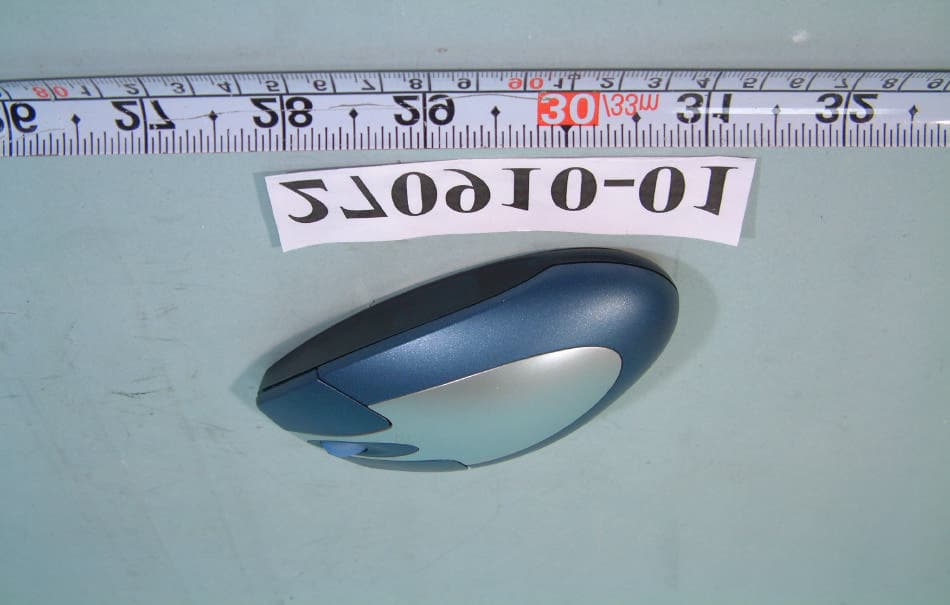
Click to zoom
Application Details
- Equipment Class
- DXX - Part 15 Low Power Communication Device Transmitter
- Date of Grant
- Jan 19, 2003
- Application Purpose
- Original Equipment
- Date of Application
- Jan 19, 2003
- Equipment Note
- RF Mouse
- Frequency Range
- 26.96000000 - 27.28000000
- Company
- Sysgration Ltd.
- Country
- Taiwan
Documents & Files
Document Text
Text extracted from the exhibit documents filed with the FCC. Open a document above to read the original.
Users Manual
User’s Guide Wireless RF Keyboard & Mouse HQXAKM-7500 HQXAGM-9600 Note: the manufacturer is not responsible for any radio or tv interference caused by unauthorized modifications to this equipment. such modifications could void the user's authority to operate the equipment. T T a a b b l l e e o o f f C C o o n n t t e e n n t t s s INTRODUCTION ............................................................................................................... 1 P ACKAGE C ONTENTS .......................................................................................................... 2 S YSTEM R EQUIREMENTS ..................................................................................................... 2 F EATURES .......................................................................................................................... 2 MAINBOARD AND MOUSE COMPONENTS ............................................................... 3 W IRELESS RF K EYBOARD .................................................................................................. 3 W IRELESS RF M OUSE ........................................................................................................ 4 RF R ECEIVER ..................................................................................................................... 4 INSERTING BATTERIES ................................................................................................. 5 M OUSE ...............................................................................................................................5 K EYBOARD ......................................................................................................................... 6 SETTING UP YOUR KEYBOARD AND MOUSE ......................................................... 7 INSTALLING THE SOFTWARE ..................................................................................... 9 M OUSE ...............................................................................................................................9 K EYBOARD ........................................................................................................................11 USING THE SOFTWARE ................................................................................................15 I W ARE M OUSE ..................................................................................................................15 M ULTIMEDIA K EYBOARD ..................................................................................................17 TROUBLESHOOTING.....................................................................................................20 A WORD ABOUT ERGONOMICS .................................................................................22 1 I I n n t t r r o o d d u u c c t t i i o o n n Congratulations on your purchase of the Wireless RF Keyboard & Mouse, which combines an innovative ergonomic design with all the features and convenience of wireless technology: Wireless RF Keyboard Wireless RF Mouse RF Receiver The Wireless RF Keyboard has advanced multimedia features that enable you to play audio CDs, VCDs, DVDs, and MPEG files. You can use the keyboard hot keys to raise, lower and mute audio. Other hot keys let you open your default Web browser and refresh Web pages, browse forward and backwards, open a search page, and send e-mail. There are also hot keys for launching the Windows calculator and entering power savings mode. The bundled software further enhances your keyboard by supplying an onscreen display (OSD) and onscreen menus to control audio and Web functions. The Wireless RF Mouse has a scroll wheel/middle button that can be assigned various functions such as Web page or word processing software scrolling, or launching applications such as Windows Explorer. 2 P P a a c c k k a a g g e e C C o o n n t t e e n n t t s s After you have unpacked the Wireless RF Keyboard & Mouse, check the contents to make sure the following items are included. • One Wireless RF Mouse • One Wireless RF Keyboard • One RF receiver • Two AAA alkaline batteries (for the mouse) • Two AA alkaline batteries (for the keyboard) • This quick guide If any of the above items are missing or appear damaged, contact your dealer im- mediately. Do not throw the shipping carton away in case you need to ship your Wireless RF Keyboard & Mouse. S S y y s s t t e e m m R R e e q q u u i i r r e e m m e e n n t t s s To use the mouse software and the hot keys on your multimedia keyboard, you need the following: • Windows ME/2000/98/95/NT 4.0 or later • PS/2 mouse and keyboard ports • Sound Blaster compatible sound card (for CD/VCD/DVD, and MPEG operation) • CD-ROM drive (for software installation and CD/VCD operation) • DVD-ROM drive (for DVD operation) F F e e a a t t u u r r e e s s • Wireless radio frequency (RF) technology • Scroll wheel mouse enables scrolling in Web pages and text editors • Onscreen display (OSD) provides status information • Keyboard multimedia and Web hot keys provide convenient access to often used commands • Plug and Play compliant • Compatible with Windows ME/2000/98/95/NT4.0 3 M M a a i i n n b b o o a a r r d d a a n n d d M M o o u u s s e e C C o o m m p p o o n n e e n n t t s s W W i i r r e e l l e e s s s s R R F F K K e e y y b b o o a a r r d d The following illustration shows the Wireless RF Keyboard and hot keys: WWW ButtonFunctionButtonFunction Play/Pause: plays or pauses a CD/DVD/VCD Forward: goes to the next page in your Web browser Mute: turns off the audio output Stop: stops loading a Web page Stop: stops playing a CD/DVD/VCD Refresh: reloads the Web page Next Track: searches back- ward through tracks on a CD/DVD/VCD WWW World Wide Web: opens your default Web browser Volume Down: decreases audio volume E-mail: launches the default e-mail application Volume Up: increases audio volume Search: opens a search window in Netscape or Windows IE Previous Track: searches forwa…
Text truncated - open the document above for the full version.
Block Diagram
2.Block Diagram of RF Mouse Mouse: When Power on, Input Voltage is first ensured to 3.0V by DC to DC , and Power Reset is done. Random Mouse ID can be sent then. After detecting motion signals from X/Y/Z Axis and also signals from buttom switches, controller would encode the signals and later modulate to 27.092MHz radio frequency and transmit to the air. 3.Block Diagram of RF Receiver Receiver: When Mouse or Keyboard sent Random ID signals, press ID switch of receiver and link between them will be set up. Any time RF signals from mouse or keyboard reach the antenna, demodulation will be done and later decoded by the controller . Finaly data of mouse and keyboard will be transfered to PC via PS/2 mouse port or PS/2 Keyboard port seperately
External Photos
FCC ID : HQXAGM-9600 FRONT SIDE OF EUT Number 1 FCC ID : HQXAGM-9600 REAR SIDE OF EUT Number 2 FCC ID : HQXAGM-9600 FRONT SIDE OF EUT Number 3 FCC ID : HQXAGM-9600 REAR SIDE OF EUT Number 4
ID Label/Location Info
AKM-7500 Mouse Label Drawing FCC ID : HQXAKM-9600
ID Label/Location Info
FCC ID : HQXAGM-9600 FCC ID LOCATION
Internal Photos
FCC ID : HQXAGM-9600 Number 1 Mechanical Construction FCC ID : HQXAGM-9600 Number 2 Mechanical Construction FCC ID : HQXAGM-9600 Number 3 Front SIDE OF Module board FCC ID : HQXAGM-9600 Number 4 REAR SIDE OF Module board FCC ID : HQXAGM-9600 Number 5 Front SIDE OF Module board FCC ID : HQXAGM-9600 Number 6 REAR SIDE OF Module board
Operational Description
2.Block Diagram of RF Mouse Mouse: When Power on, Input Voltage is first ensured to 3.0V by DC to DC , and Power Reset is done. Random Mouse ID can be sent then. After detecting motion signals from X/Y/Z Axis and also signals from buttom switches, controller would encode the signals and later modulate to 27.092MHz radio frequency and transmit to the air. 3.Block Diagram of RF Receiver Receiver: When Mouse or Keyboard sent Random ID signals, press ID switch of receiver and link between them will be set up. Any time RF signals from mouse or keyboard reach the antenna, demodulation will be done and later decoded by the controller . Finaly data of mouse and keyboard will be transfered to PC via PS/2 mouse port or PS/2 Keyboard port seperately
Schematics
1 2 34 ABCD 4 3 2 1 D CBA Title Number Revision Size A Date: 26-Jun-2002 Sheet of File: D :\protel\Mouse\SYS-0418\SYS-0418.ddb Drawn By: TXCB 7 TXD 6 BBUT 5 FBUT 4 OSC2 3 OSC1 2 VDD 1 VSS 8 RFCTL 9 RFOUT 10 ORF1 11 ORF2 12 TEST 13 XRESET 14 XIR 15 Z1IN 16 Z2IN 17 X1IN 18 X2IN 19 Y1IN 20 Y2IN 21 RBUT 22 MBUT 23 LBUT 24 ZSO 25 DCVR 26 VL 27 VSSS 28 U1MA60H09 PCBANT + 1 - 2 VBAT UM-4(X2) PS2 MOUSE Transmitter 12 R110M 1 2 L1100U 1 2 L21.8U 12 L3 0.82U 12 R8100K 12 R7220K 12 D1RB421 12 + C18470U 12 + C16100U 12 C15104 12 C17104 12 X1 76.8K 1 2 C247P 1 2 C347P 1 2 C1104P 1 2 SWID 1 2 SW4 1 2 SW5 1 2 C433P 12 C933P 12 C103P 1 2 C533P 1 2 C675P 12 C724P 1 2 C8240P XL2 27.042MHz PC02010B24B 75# B.VER VCC 123456 CN-2 Z2Z1Y1Y2XIRVDD 12345678 CN-1 MLRVCCX1GNDX2NC VDD TP1 TP2 TP3 TP4 TP5 TP6 TP7 TP8 SYSGRATION LTD
Schematics
1 2 3 4 ABCD 4 3 2 1 D CBA Title Number Revision Size A4 Date: 26-Jun-2002 Sheet of File: D:\protel\Mouse\SYS-0418\SYS-0418.ddb Drawn By: 1 2 SW1 1 2 SW2 1 2 SW3 2 3 1 3 SWSGSW ENCODER 12 R347K 12 R447K 12 R547K 12 R647K 1 2 R2220 1 2 IR2 1 2 IR1 12 R910 12 + C14 100U 2 PT1 2 PT2 123456 CN-2 12345678 CN-1 ML VCC R VCC Z2Z1 VCC PC02010B23A Y1Y2XIRVDDVCCX1GNDX2NC VDD 75# B.VER TX SW SYSGRATION LTD
Test Report
FCC TEST REPORT Report No. : F270910 SPORTON International Inc. TEL : 886-2-2696-2468 FAX : 886-2-2696-2255 FCC TEST REPORT for 47 CFR, Part 15, Subpart C Equipment : RF Mouse and Keyboard (Mouse) Model No. : AKM-7500X, AKM-9600X, 41162B, A-AKM-7500X, XK-220, 86017, 86013, 86007, 86023, WK930, AKM-7500, 0186403480, 62052S, AKM-7500, MT134, WCPA0D FCC ID : HQXAGM-9600 Filing Type : Certification Applicant : Sysgration Ltd. 8F, No. 542-7, Chung Cheng Rd., Hsin Tien, Taipei, Taiwan, R.O.C. † The test result refers exclusively to the test presented test model / sample. † Without written approval of SPORTON International Inc., the test report shall not be reproduced except in full. † Certificate or Test Report must not be used by the applicant to claim the product in this test report endorsement by NVLAP or any agency of U.S. government. SPORTON International Inc. 6F, No.106, Sec. 1, Hsin Tai Wu Rd., Hsi Chih, Taipei Hsien, Taiwan, R.O.C. FCC TEST REPORT Report No. : F270910 SPORTON International Inc. FCC ID : HQXAGM-9600 TEL : 886-2-2696-2468 Page No. : i FAX : 886-2-2696-2255 Issued Date : Aug. 23, 2002 Table of Contents History of this test report.........................................................................................................................ii CERTIFICATE OF COMPLIANCE..............................................................................................................1 1. General Description of Equipment under Test.....................................................................................2 1.1. Applicant.......................................................................................................................................................................................2 1.2. Manufacturer.................................................................................................................................................................................2 1.3. Basic Description of Equipment under Test...................................................................................................................................2 1.4. Feature of Equipment under Test..................................................................................................................................................2 2. Test Configuration of Equipment under Test.......................................................................................3 2.1. Test Manner..................................................................................................................................................................................3 2.2. Description of Test System...........................................................................................................................................................3 2.3. Band edge compliance plot per 15.227(b).....................................................................................................................................5 2.4. Connection Diagram of Test System.............................................................................................................................................6 3. General Information of Test.................................................................................................................7 3.1. Test Facility...................................................................................................................................................................................7 3.2. Standard for Methods of Measurement.........................................................................................................................................7 3.3. Test in Compliance with................................................................................................................................................................7 3.4. Frequency Range Investigated......................................................................................................................................................7 3.5. Test Distance................................................................................................................................................................................7 4. Test of Conducted Powerline...............................................................................................................8 5. Test of Radiated Emission...................................................................................................................9 5.1. Major Measuring Instruments........................................................................................................................................................9 5.2. Test Procedures..........................................................................................................................................................................10 5.3. Typical Test Setup Layout of Radiated Emission........................................................................................................................11 5.4. Test Result of Radiated Emission...............................................................................................................................................12 6. EMI Suppression Component List.......................................................................................................13 7. Antenna Factor & Cable Loss.............................................................................................................14 8. List of Measuring Equipments Used...................................................................................................15 9. Uncertainty of Test Site.......................................................................................................................16 Appendix A. Photographs of EUT...........................................................................................…
Text truncated - open the document above for the full version.
Test Setup Photos
FCC TEST REPORT Report No. : F270910 SPORTON International Inc. FCC ID : HQXAGM-9600 TEL : 886-2-2696-2468 Page No. : 1 of 1 FAX : 886-2-2696-2255 Issued Date : Dec. 26. 2002 1.1. Photographs of Radiated Emission Test Configuration l The photographs show the configuration that generates the maximum emission. FRONT VIEW REAR VIEW
Contact Information
Applicant
Ken Chen(Manager)
Test Firm
SPORTON International IncKathy Lin
Technical Specifications
| # | Rule Parts | Frequency Range | Power Output |
|---|---|---|---|
| 1 | 15C | 26.96 MHz - 27.28 MHz | - |
Other Applications from Sysgration Ltd.
HQXSWA02
Jun 03, 2026TPMS
Equipment Class
DSR - Part 15 Remote Control/Security Device Transceiver
HQXBSI1505
Dec 02, 2025TPMS-VALVE ASSY, BLE
Equipment Class
DTS - Digital Transmission System
HQXRSI30
Sep 02, 2024TPMS
Equipment Class
DSC - Part 15 Security/Remote Control Transmitter
HQXTT03
Jul 01, 2024TPMS Trigger
Equipment Class
DCD - Part 15 Low Power Transmitter Below 1705 kHz
HQXTT02
May 27, 2020TPMS Trigger
Equipment Class
DCD - Part 15 Low Power Transmitter Below 1705 kHz