HQXAKM-K02WIRELESS KEYBOARD
Sysgration Ltd.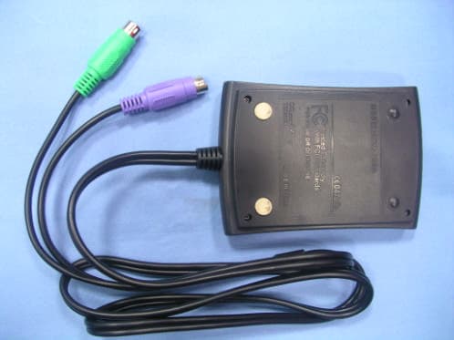
Click to zoom
Application Details
- Equipment Class
- DXX - Part 15 Low Power Communication Device Transmitter
- Date of Grant
- Aug 03, 2004
- Application Purpose
- Original Equipment
- Date of Application
- Aug 03, 2004
- Equipment Note
- WIRELESS KEYBOARD
- Frequency Range
- 27.09500000 - 27.09500000
- Company
- Sysgration Ltd.
- Country
- Taiwan
Documents & Files
Document Text
Text extracted from the exhibit documents filed with the FCC. Open a document above to read the original.
Block Diagram
Wireless Keyboard Block Diagram ID SW Key Matrix Battery Low Detect OSC Micro-controller AMP 32.768KHz 27.092MHz 27.095MHz DC/DC Converter Battery 2*AA When Power on, Input Voltage is first ensured to 3.0V by DC to DC convertor, and Power Reset is done. Random Keyboard ID can be sent then. After detecting signals from Keymatrix , controller would encode the signals and later modulate to 27.095MHz radio frequency and transmit to the air. Wireless Receiver Block Diagram 26.59MHz 27.045MHz, 27.095MHz ID SW Detector PC Demodulation Mouse / KeyBoard Micro-controller Receiver: When Mouse & Keyboard send Random ID signals, press ID switch of the receiver and link between them will be set up. Any time RF signals from mouse or keyBoard reach the Antenna, demodulation will be done and later decoded by the controller. Finally data of mouse and keyboard will be transfered to PC via PS/2 mouse port or PS/2 keyboard port seperately. 32.768KHz 26.64MHz Demodulation PS/2 Mouse Port PS/2 Ke y Board Port
External Photos
Part I : TX (Keyboard) PHOTOS OF EUT Part I : RX (Receiver) PHOTOS OF EUT
ID Label/Location Info
Sample of FCC ID Label FCC ID: HQXAKM-K02 THIS DEVICE COMPLIES WITH PART 15 OF THE FCC RULES. OPERATION IS SUBJECT TO THE FOLLOWING TWO CONDITIONS. (1) THIS DEVICE MAY NOT CAUSE HARMFUL INTERFERENCE AND (2) THIS DEVICE MUST ACCEPT ANY INTERFERENCE RECEIVED, INCLUDING INTERFERENE THAT MAY CAUSE UNDESIRED OPERATION. Sample of FCC DoC Label Trade Name Model Number Tested To Comply With FCC Standards FOR HOME OR OFFICE USE We remove the Two-Part statement from the device since we already have it in the manual.
Internal Photos
Spectrum Research & Testing Lab., Inc. No. 101-10, Ling 8, Shan-Tong Li, Chung-Li City, Taoyuan, Taiwan, R.O.C. Photo Page: 1 of 7 Part I : TX (Keyboard) PHOTOS OF EUT Spectrum Research & Testing Lab., Inc. No. 101-10, Ling 8, Shan-Tong Li, Chung-Li City, Taoyuan, Taiwan, R.O.C. Photo Page: 2 of 7 PHOTOS OF EUT Spectrum Research & Testing Lab., Inc. No. 101-10, Ling 8, Shan-Tong Li, Chung-Li City, Taoyuan, Taiwan, R.O.C. Photo Page: 3 of 7 PHOTOS OF EUT Spectrum Research & Testing Lab., Inc. No. 101-10, Ling 8, Shan-Tong Li, Chung-Li City, Taoyuan, Taiwan, R.O.C. Photo Page: 4 of 7 PHOTOS OF EUT Spectrum Research & Testing Lab., Inc. No. 101-10, Ling 8, Shan-Tong Li, Chung-Li City, Taoyuan, Taiwan, R.O.C. Photo Page: 5 of 7 PHOTOS OF EUT Spectrum Research & Testing Lab., Inc. No. 101-10, Ling 8, Shan-Tong Li, Chung-Li City, Taoyuan, Taiwan, R.O.C. Photo Page: 6 of 7 Part I : RX (Receiver) PHOTOS OF EUT Spectrum Research & Testing Lab., Inc. No. 101-10, Ling 8, Shan-Tong Li, Chung-Li City, Taoyuan, Taiwan, R.O.C. Photo Page: 7 of 7 PHOTOS OF EUT
Operational Description
FCC ID: HQXAKM-K02 Operational Description of the equipment The EUT is an excellent tool for mobile professionals. The equipment consists of the following: Keyboard Transmitter + Receiver Wireless keyboard: When Power on, Input Voltage is first ensured to 3.0V by DC to DC conver5tor, and Power Reset is done. Random Keyboard ID can be sent then. After detecting signals from Keymatrix, controller would encode the signals and later modulate to 27.095MHz radio frequecy and transmit to the air. Receiver: When Mouse & Keyboard send Random ID signals, press ID switch of the receiver and link between them will be set up. Any time RF signals from mouse or keyboard reach the Antenna, demodulation will be done and later decoded by the controller. Finally data of mouse and keyboard will be transferred to PC via PS/2 mouse port of PS/2 keyboard port seperately. PRODUCT Wireless Keyboard MODEL NO. AKM-K02xxx, AKM-A5K02, AKM-A6K02, AKM-A7K02, AKM-A8K02, AKM-A9K02, AKM-B0K02, AKM-B3K02, AKM-B4K02, AKM-B5K02 BRAND NAME Agiler, Sysgration POWER SUPPLY 3Vdc, 8mA from battery (AA x 2) for transmitter part 5Vdc from PC system for receiver part CABLE 1.1m unshielded data cable for receiver part CARRIER FREQUENCY 27.095 MHz NUMBER OF CHANNEL 1 RATED RF OUTPUT POWER 2dBm I.F. & L.O. I.F.: 455KHz, L.O.: 32.768KHz MODULATION TYPE FSK BIT RATE OF TRANSMISSION 4kbps ANTENNA TYPE Loop Antenna ANTENNA GAIN 0dBi NOTE : The product is a wireless keyboard which includes transmitter part (TX) and receiver part (RX). The “x” in the model numbers can be 0-9, A-Z or blank. It is indicated that different between color of enclosure and customer. The EUT has several model numbers as above on market. They are identical in all aspects except for support wireless mouse(manufacturer must be Sysgtation Ltd.). The model no.: AKM-K02 was chosen as the representative for testing. For more detailed features, please refer to the manufacturer’s specification or User’s Manual.
Test Report
Spectrum Research & Testing Lab., Inc. No. 101-10, Ling 8, Shan-Tong Li, Chung-Li City, Taoyuan, Taiwan, R.O.C. TEST REPORT Reference No.:A04061502 Report No.:FCBA04061502 Page:2 of 16 Date:Jul. 27, 2004 Table of Contents 1. DOCUMENT POLICY AND TEST STATEMENT......................................................3 1.1 DOCUMENT POLICY....................................................................................................3 1.2 TEST STATEMENT........................................................................................................3 2. DESCRIPTION OF EUT AND TEST MODE.............................................................4 2.1 GENERAL DESCRIPTION OF EUT............................................................................4 2.2 DESCRIPTION OF EUT INTERNAL DEVICE...........................................................4 2.3 DESCRIPTION OF TEST MODE.................................................................................4 2.4 DESCRIPTION OF SUPPORT UNIT..........................................................................5 3. DESCRIPTION OF APPLIED STANDARDS.............................................................5 4. CONDUCTED EMISSION TEST.................................................................................6 4.1 CONDUCTED EMISSION LIMIT.................................................................................6 4.2 TEST EQUIPMENT........................................................................................................6 4.3 TEST SETUP..................................................................................................................7 4.4 TEST PROCEDURE......................................................................................................7 4.5 EUT OPERATING CONDITION...................................................................................7 4.6 TEST RESULT................................................................................................................8 5. RADIATED EMISSION TEST......................................................................................9 5.1 RADIATED EMISSION LIMIT.......................................................................................9 5.2 TEST EQUIPMENT.....................................................................................................10 5.3 TEST SET-UP...............................................................................................................11 5.4 TEST PROCEDURE...................................................................................................12 5.5 EUT OPERATING CONDITION................................................................................12 5.6 RADIATED EMISSION TEST RESULT...................................................................13 6. PHOTOS OF TESTING..............................................................................................14 7. TERMS OF ABRIVATION...........................................................................................16 Spectrum Research & Testing Lab., Inc. No. 101-10, Ling 8, Shan-Tong Li, Chung-Li City, Taoyuan, Taiwan, R.O.C. TEST REPORT Reference No.:A04061502 Report No.:FCBA04061502 Page:3 of 16 Date:Jul. 27, 2004 1. DOCUMENT POLICY AND TEST STATEMENT 1.1 DOCUMENT POLICY - The report shall not be reproduced except in full, without the written approval of SRT Lab, Inc. - The report must not be used by the applicant to claim that the product is endorsed by NVLAP, TÜV, NEMKO and SRT. - The NVLAP logo applies only to the applicable standards specified in this report. 1.2 TEST STATEMENT - The test results in the report apply only to the unit tested by SRT Lab. - There was no deviation from the requirements of test standards during the test. - AC power source, 120 Vac/60 Hz, was used during the test. Spectrum Research & Testing Lab., Inc. No. 101-10, Ling 8, Shan-Tong Li, Chung-Li City, Taoyuan, Taiwan, R.O.C. TEST REPORT Reference No.:A04061502 Report No.:FCBA04061502 Page:4 of 16 Date:Jul. 27, 2004 2. DESCRIPTION OF EUT AND TEST MODE 2.1 GENERAL DESCRIPTION OF EUT PRODUCT Wireless Keyboard MODEL NO. AKM-K02xxx, AKM-A5K02, AKM-A6K02, AKM-A7K02, AKM-A8K02, AKM-A9K02, AKM-B0K02, AKM-B3K02, AKM-B4K02, AKM-B5K02 BRAND NAME Agiler, Sysgration POWER SUPPLY 3Vdc, 8mA from battery (AA x 2) for transmitter part 5Vdc from PC system for receiver part CABLE 1.1m unshielded data cable for receiver part CARRIER FREQUENCY 27.095 MHz NUMBER OF CHANNEL 1 RATED RF OUTPUT POWER 2dBm I.F. & L.O. I.F.: 455KHz, L.O.: 32.768KHz MODULATION TYPE FSK BIT RATE OF TRANSMISSION 4kbps ANTENNA TYPE Loop Antenna ANTENNA GAIN 0dBi NOTE : The product is a wireless keyboard which includes transmitter part (TX) and receiver part (RX). The “x” in the model numbers can be 0-9, A-Z or blank. It is indicated that different between color of enclosure and customer. The EUT has several model numbers as above on market. They are identical in all aspects except for support wireless mouse(manufacturer must be Sysgtation Ltd.). The model no.: AKM-K02 was chosen as the representative for testing. For more detailed features, please refer to the manufacturer’s specification or User’s Manual. 2.2 DESCRIPTION OF EUT INTERNAL DEVICE DEVICE BRAND/MAKER MODEL # FCC ID/DOC REMARK N/A 2.3 DESCRIPTION OF TEST MODE N/A (It is only applicable to more than one test mode.) Spectrum Research & Testing Lab., Inc. No. 101-10, Ling 8, Shan-Tong Li, Chung-Li City, Taoyuan, Taiwan, R.O.C. TEST REPORT Reference No.:A04061502 Report No.:FCBA04061502 Page:5 of 16 Date:Jul. 27, 2004 2.4 DESCRIPTION OF SUPPORT UNIT The EUT was configured by the requirement of ANSI C63.4:2003 and CISRP22:2003. All interface ports were connected to the appropriate support units via specific cables. The support units and cables are listed below. NO DEVICE BRAND MODEL # FCC ID/DOC CABLE 1 PC ACER VT7600 DOC 1.8m unshielded power cord 2 MODEM ACEEX DM-1414 DOC 1.5m unshielded power cord 1.5m…
Text truncated - open the document above for the full version.
Test Report
Spectrum Research & Testing Lab., Inc. No. 101-10, Ling 8, Shan-Tong Li, Chung-Li City, Taoyuan, Taiwan, R.O.C. TEST REPORT Reference No.:A04061502 Report No.:FCCA04061502 Page:2 of 21 Date:Jul. 27, 2004 FCC ID:HQXAKM-02 Table of Contents 1. DOCUMENT POLICY AND TEST STATEMENT......................................................3 1.1 DOCUMENT POLICY....................................................................................................3 1.2 TEST STATEMENT........................................................................................................3 2. DESCRIPTION OF EUT AND TEST MODE.............................................................4 2.1 GENERAL DESCRIPTION OF EUT............................................................................4 2.2 DESCRIPTION OF EUT INTERNAL DEVICE...........................................................4 2.3 DESCRIPTION OF TEST MODE.................................................................................4 2.4 DESCRIPTION OF SUPPORT UNIT..........................................................................5 3. DESCRIPTION OF APPLIED STANDARDS.............................................................5 4. CONDUCTED EMISSION TEST.................................................................................6 4.1 CONDUCTED EMISSION LIMIT.................................................................................6 4.2 TEST EQUIPMENT........................................................................................................6 4.3 TEST SETUP..................................................................................................................7 4.4 TEST PROCEDURE......................................................................................................7 4.5 EUT OPERATING CONDITION...................................................................................7 4.6 TEST RESULT................................................................................................................8 5. RADIATED EMISSION TEST......................................................................................9 5.1 RADIATED EMISSION LIMIT.......................................................................................9 5.2 TEST EQUIPMENT.....................................................................................................10 5.3 TEST SET-UP...............................................................................................................11 5.4 TEST PROCEDURE...................................................................................................12 5.5 EUT OPERATING CONDITION................................................................................12 5.6 RADIATED EMISSION TEST RESULT...................................................................13 6. BAND EDGE.................................................................................................................16 6.1 BAND EDGE LIMIT.....................................................................................................16 6.2 TEST EQUIPMENT.....................................................................................................16 6.3 TEST SET-UP..............................................................................................................16 6.4 TEST PROCEDURE...................................................................................................16 6.5 EUT OPERATING CONDITION................................................................................16 6.6 BAND EDGE TEST RESULT.....................................................................................17 7. PHOTOS OF TESTING..............................................................................................18 8. TERMS OF ABRIVATION...........................................................................................21 Spectrum Research & Testing Lab., Inc. No. 101-10, Ling 8, Shan-Tong Li, Chung-Li City, Taoyuan, Taiwan, R.O.C. TEST REPORT Reference No.:A04061502 Report No.:FCCA04061502 Page:3 of 21 Date:Jul. 27, 2004 FCC ID:HQXAKM-02 1. DOCUMENT POLICY AND TEST STATEMENT 1.1 DOCUMENT POLICY - The report shall not be reproduced except in full, without the written approval of SRT Lab, Inc. - The report must not be used by the applicant to claim that the product is endorsed by NVLAP, TÜV, NEMKO and SRT. - The NVLAP logo applies only to the applicable standards specified in this report. 1.2 TEST STATEMENT - The test results in the report apply only to the unit tested by SRT Lab. - There was no deviation from the requirements of test standards during the test. - AC power source, 120 Vac/60 Hz, was used during the test. Spectrum Research & Testing Lab., Inc. No. 101-10, Ling 8, Shan-Tong Li, Chung-Li City, Taoyuan, Taiwan, R.O.C. TEST REPORT Reference No.:A04061502 Report No.:FCCA04061502 Page:4 of 21 Date:Jul. 27, 2004 FCC ID:HQXAKM-02 2. DESCRIPTION OF EUT AND TEST MODE 2.1 GENERAL DESCRIPTION OF EUT PRODUCT Wireless Keyboard MODEL NO. AKM-K02xxx, AKM-A5K02, AKM-A6K02, AKM-A7K02, AKM-A8K02, AKM-A9K02, AKM-B0K02, AKM-B3K02, AKM-B4K02, AKM-B5K02 BRAND NAME Agiler, Sysgration POWER SUPPLY 3Vdc, 8mA from battery (AA x 2) for transmitter part 5Vdc from PC system for receiver part CABLE 1.1m unshielded data cable for receiver part CARRIER FREQUENCY 27.095 MHz NUMBER OF CHANNEL 1 RATED RF OUTPUT POWER 2dBm I.F. & L.O. I.F.: 455KHz, L.O.: 32.768KHz MODULATION TYPE FSK BIT RATE OF TRANSMISSION 4kbps ANTENNA TYPE Loop Antenna ANTENNA GAIN 0dBi NOTE : The product is a wireless keyboard which includes transmitter part (TX) and receiver part (RX). The “x” in the model numbers can be 0-9, A-Z or blank. It is indicated that different between color of enclosure and customer. The EUT has several model numbers as above on market. They are identical in all aspects except for support wireless mouse(manufacturer must be Sysgtation Ltd.). The model no.: AKM-K02 was chosen as th…
Text truncated - open the document above for the full version.
Test Setup Photos
PHOTOS OF TESTING - Conducted test - Radiated test (TX) - Radiated test (RX)
Contact Information
Applicant
Arthur Dai(Manager)
Test Firm
Spectrum Research & Testing Lab.Linda Chiang
Technical Specifications
| # | Rule Parts | Frequency Range | Power Output |
|---|---|---|---|
| 1 | 15C | 27.095 MHz - 27.095 MHz | - |
Other Applications from Sysgration Ltd.
HQXSWA02
Jun 03, 2026TPMS
Equipment Class
DSR - Part 15 Remote Control/Security Device Transceiver
HQXBSI1505
Dec 02, 2025TPMS-VALVE ASSY, BLE
Equipment Class
DTS - Digital Transmission System
HQXRSI30
Sep 02, 2024TPMS
Equipment Class
DSC - Part 15 Security/Remote Control Transmitter
HQXTT03
Jul 01, 2024TPMS Trigger
Equipment Class
DCD - Part 15 Low Power Transmitter Below 1705 kHz
HQXTT02
May 27, 2020TPMS Trigger
Equipment Class
DCD - Part 15 Low Power Transmitter Below 1705 kHz