HQXAM7500Wireless Mouse
Sysgration Ltd.
Click to zoom
Application Details
- Equipment Class
- DXX - Part 15 Low Power Communication Device Transmitter
- Date of Grant
- Dec 27, 2001
- Application Purpose
- Original Equipment
- Date of Application
- Dec 27, 2001
- Equipment Note
- Wireless Mouse
- Frequency Range
- 27.04500000 - 27.04500000
- Company
- Sysgration Ltd.
- Country
- Taiwan
Documents & Files
Document Text
Text extracted from the exhibit documents filed with the FCC. Open a document above to read the original.
Users Manual
Wireless RF Keyboard & Mouse P P R R E E F F A A C C E E R R & & T T T T E E C C o o m m p p l l i i a a n n c c e e S S t t a a t t e e m m e e n n t t This equipment complies with all the requirements of the DIRECTIVE 1999/5/EC OF THE EUROPEAN PARLIAMENT AND THE COUNCIL OF 9 March 1999 on radio equipment and telecommunication terminal equipment and the mutual recognition of their conformity (R&TTE). S S a a f f e e t t y y This equipment is designed with the utmost care for the safety of those who install and use it. However, special attention must be paid to the dangers of electric shock and static electricity when working with electrical equipment. All guidelines of this manual and of the computer manufacturer must therefore be allowed at all times to ensure the safe use of the equipment. F F e e d d e e r r a a l l C C o o m m m m u u n n i i c c a a t t i i o o n n s s C C o o m m m m i i s s s s i i o o n n R R a a d d i i o o ( ( F F C C C C ) ) S S t t a a t t e e m m e e n n t t This equipment has been tested and found to comply with the limits for a Class B digital de- vice, pursuant to Part 15 of the FCC Rules. These limits are designed to provide reasonable protection against harmful interference in a residential installation. This equipment generates, uses, and can radiate radio frequency energy and if not installed and used in accordance with the instruction manual may cause harmful interference to radio communications. However, there is no guarantee that interference will not occur in a particular installation. If this equip- ment does cause harmful interference to radio or television reception, which can be determined by turning the equipment off and on, the user is encouraged to try to correct the interference by one or more of the following measures: − Reorient or relocate the receiving antenna. − Increase the separation between the equipment and receiver. − Connect the equipment into an outlet on a circuit different from that to which the receiver is connected. − Consult the dealer or an experienced radio TV technician for help. T T a a b b l l e e o o f f C C o o n n t t e e n n t t s s INTRODUCTION................................................................................................................1 PACKAGE CONTENTS...........................................................................................................2 SYSTEM REQUIREMENTS......................................................................................................2 FEATURES...........................................................................................................................2 MAINBOARD AND MOUSE COMPONENTS................................................................3 WIRELESS RF KEYBOARD...................................................................................................3 WIRELESS RF MOUSE.........................................................................................................4 RF RECEIVER......................................................................................................................4 INSERTING BATTERIES..................................................................................................5 MOUSE................................................................................................................................5 KEYBOARD..........................................................................................................................6 SETTING UP YOUR KEYBOARD AND MOUSE..........................................................7 INSTALLING THE SOFTWARE......................................................................................9 MOUSE................................................................................................................................9 KEYBOARD........................................................................................................................11 USING THE SOFTWARE................................................................................................15 IWARE MOUSE..................................................................................................................15 MULTIMEDIA KEYBOARD..................................................................................................17 TROUBLESHOOTING.....................................................................................................20 A WORD ABOUT ERGONOMICS.................................................................................22 SPECIFICATIONS............................................................................................................23 1 I I n n t t r r o o d d u u c c t t i i o o n n Congratulations on your purchase of the Wireless RF Keyboard & Mouse, which combines an innovative ergonomic design with all the features and convenience of wireless technology: Wireless RF Keyboard Wireless RF Mouse RF Receiver The Wireless RF Keyboard has advanced multimedia features that enable you to play audio CDs, VCDs, DVDs, and MPEG files. You can use the keyboard hot keys to raise, lower and mute audio. Other hot keys let you open your default Web browser and refresh Web pages, browse forward and backwards, open a search page, and send e-mail. There are also hot keys for launching the Windows calculator and entering power savings mode. The bundled software further enhances your keyboard by supplying an onscreen display (OSD) and onscreen menus to control audio and Web functions. The Wireless RF Mouse has a scroll wheel/middle button that can be assigned various functions such as Web page or word processing software scrolling, or launching applications such as Windows Explorer. 2 P P a a c c k k a a g g e e C C o o n n t t e e n n t t s s After you have unpacked the Wireless RF Keyboard & Mouse, check the contents to make sure the following items are included. • One Wireless RF Mouse • One Wireless RF Keyboard • One RF receiv…
Text truncated - open the document above for the full version.
Operational Description
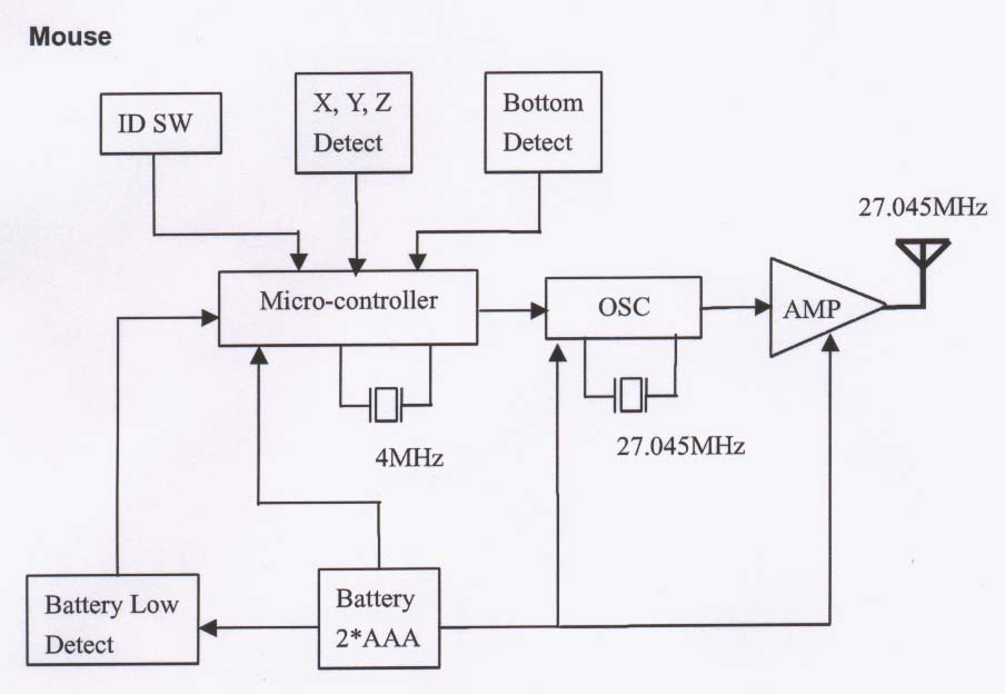
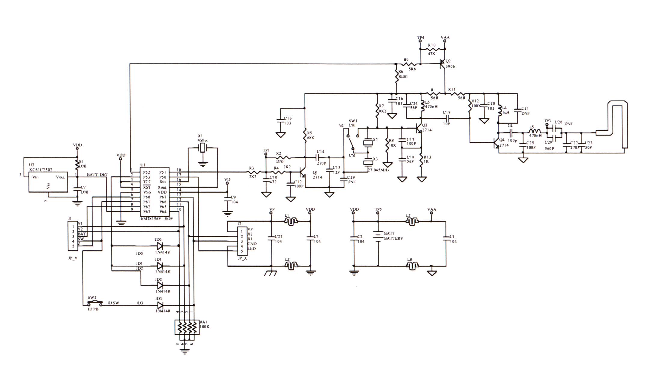
SYS K&M 27MHz Block Diagram 1. Block Diagram of RF Keyboard ID SW Key Matrix Battery Low Detect OSC Micro-controller AMP 2MHz 27.145MHz 27.145MHz DC/DC Convert Battery 2*AA Model No.: AK7500 I.D.: HQXAK7500 KB: When Power on, Micro controller is starting to detect the function input signal. Ex: ID switch, Key matrix After detecting signals, micro controller encoder data and send data to OSC and local OSC. Then modulation through AMP and turned to radio signal. 2. Block Diagram of RF Mouse ID SW X, Y, Z Detect Bottom Detect Battery Low Detect Battery 2*AAA OSC Micro-controller AMP 4MHz 27.045MHz 27.045MHz Model No.: AM7500 I.D.: HQXAM7500 Mouse: When Power on, Micro controller is starting to detect the function input signal. Ex: ID switch, X,Y,Z axis motion detect, battery low detect. After detecting signals, micro controller encoder data and send data to OSC and local OSC. Then modulation through AMP and turned to radio signal. 3.Block Diagram of RF Receiver +5V 4MHz 26.59MHz 27.045MHz 27.145MHz ID SWDetector PC 4MHz 26.69MHz +5V Demodulation n KB Micro-controller MS Micro-controller Demodulation n Model No.: AR7500 Receiver: When power on, the micro controller of keyboard & mouse will send data and communicate with PC. RF receive signal through antenna and through de-modulation IC (3361) and LO ( 26.59 or 26.69 MHz) send signal to PC.
Test Report
FCC ID.:HQXAM7500 Rev. No 1.0 FCC Part 15 Subpart C EMI TEST REPORT of E.U.T. : Wireless Mouse FCC ID. : HQXAM7500 MODEL : AM7500 Working Frequency : 27.045MHz Issused Dated : Nov. 14, 2001 for APPLICANT: SYSGRATION LTD. ADDRESS: 8Fl., No.542-7, Chung Cheng Rd., Hsin Tien, Taipei, Taiwan, R.O.C. Test Performed by ELECTRONICS TESTING CENTER, TAIWAN NO. 8 LANE 29, WENMIMG ROAD, LOSHAN TSUN, KWEISHAN HSIANG, TAOYUAN, TAIWAN, R.O.C. Tel:(03)3276170-3276174 Fax:(03)3276188 Report Number : ET90S-10-017-03 ETC Report No.:ET90S-10-017-03FCC ID.: HQXAM7500 Rev. No 1.0 TEST REPORT CERTIFICATION Applicant: SYSGRATION LTD. 8Fl., No. 542-7, Chung Cheng Rd., Hsin Tien, Taipei, Taiwan, R.O.C. Manufacturer: SYSGRATION (Shenzhen) LTD. Egongling Village, Pinhu Town, Longgang, Shenzhen City, Guang Dong, China Description of EUT: a) Type of EUT: Wireless Mouse b) Trade Name: SYSGRATION or Agiler c) Model No.: AM7500 d) FCC ID: HQXAM7500 e) Working Frequency: 27.045MHz f) Power Supply: DC 3V Battery Regulation Applied: FCC Rules and Regulations Part 15 Subpart C (1996) I HEREBY CERTIFY THAT; The data shown in this report were made in accordance with the procedures given in ANSI C63.4 and the energy emitted by the device was founded to be within the limits applicable. I assume full responsibility for accuracy and completeness of these data. Note : 1. The results of the testing report relate only to the items tested. 2. The testing report shall not be reproduced except in full, without the written approval of ETC. Test Date : Oct. 24, 2001 Test Engineer : Approve & Authorized Signer : Win-Po Tsai, Manager, NVLAP Signatory EMC Dept. I of ELECTRONICS TESTING CENTER, TAIWAN ETC Report No.:ET90S-10-017-03FCC ID.: HQXAM7500 Rev. No 1.0 Table of Contents Page 1. GENERAL INFORMATION............................................................................................................................................................1 1.1 PRODUCT DESCRIPTION...................................................................................................................................................................1 1.2 CHARACTERISTICS OF DEVICE:.......................................................................................................................................................1 1.3 TEST METHODOLOGY......................................................................................................................................................................1 1.4 TEST FACILITY..................................................................................................................................................................................1 2. DEFINITION AND LIMITS..............................................................................................................................................................2 2.1 DEFINITION........................................................................................................................................................................................2 2.2 RESTRICTED BANDS OF OPERATION.............................................................................................................................................2 2.3 LIMITATION.......................................................................................................................................................................................2 2.4 LABELING REQUIREMENT...............................................................................................................................................................4 2.5 USER INFORMATION.........................................................................................................................................................................4 3. RADIATED EMISSION MEASUREMENT....................................................................................................................................5 3.1 APPLICABLE STANDARD.................................................................................................................................................................5 3.2 DEVICES FOR TESTED SYSTEM.......................................................................................................................................................5 3.3 MEASUREMENT PROCEDURE..........................................................................................................................................................5 3.4 TEST DATA.........................................................................................................................................................................................8 3.5 FIELD STRENGTH CALCULATION................................................................................................................................................12 3.6 RADIATED TEST EQUIPMENT.......................................................................................................................................................12 3.7 MEASURING INSTRUMENT SETUP...............................................................................................................................................13 3.7 RADIATED MEASUREMENT PHOTOS...........................................................................................................................................13 4. CONDUCTED EMISSION MEASUREMENT.............................................................................................................................14 4.1APPLICABLE STANDARD...............................................................................................................................................................14 5. BANDEDGE COMPLIANCE MEASUREMENT.........................................................................................................................14 PHOTOS OF RADIATION MEASURING SETUP........…
Text truncated - open the document above for the full version.
Test Setup Photos
ETC Report No.:ET90S-10-017-03Page A1 of A1 FCC ID.: HQXAM7500 Rev. No 1.0 Photos of Radiation Measuring Setup
Contact Information
Applicant
Ken Chen(Manager)
Test Firm
Electronics Testing Center, TaiwanWin-Po Tsai
Technical Specifications
| # | Rule Parts | Frequency Range | Power Output |
|---|---|---|---|
| 1 | 15C | 27.045 MHz - 27.045 MHz | - |
Other Applications from Sysgration Ltd.
HQXSWA02
Jun 03, 2026TPMS
Equipment Class
DSR - Part 15 Remote Control/Security Device Transceiver
HQXBSI1505
Dec 02, 2025TPMS-VALVE ASSY, BLE
Equipment Class
DTS - Digital Transmission System
HQXRSI30
Sep 02, 2024TPMS
Equipment Class
DSC - Part 15 Security/Remote Control Transmitter
HQXTT03
Jul 01, 2024TPMS Trigger
Equipment Class
DCD - Part 15 Low Power Transmitter Below 1705 kHz
HQXTT02
May 27, 2020TPMS Trigger
Equipment Class
DCD - Part 15 Low Power Transmitter Below 1705 kHz