HQXFTR-CBX3000FM Modulator
Sysgration Ltd.
Click to zoom
Application Details
- Equipment Class
- DXX - Part 15 Low Power Communication Device Transmitter
- Date of Grant
- Aug 18, 2004
- Application Purpose
- Original Equipment
- Date of Application
- Aug 18, 2004
- Equipment Note
- FM Modulator
- Frequency Range
- 88.30000000 - 90.30000000
- Company
- Sysgration Ltd.
- Country
- Taiwan
Documents & Files
Document Text
Text extracted from the exhibit documents filed with the FCC. Open a document above to read the original.
Users Manual
Owner's Manual HMD-0702 Headrest Video Monitor with Built-in DVD It is unlawful in most jurisdictions for a person to drive a motor vehicle which is equipped with a television viewer or screen that is located in the motor vehicle at any point forward of the back of the driver's seat, or that is visible, directly or indirectly, to the driver while operating the vehicle. In the interest of safety, the unit should never be installed where it will be visible, directly or indirectly, by the operator of the motor vehicle. This device complies with FCC Rules Part 15. Operation is subject to the following two conditions: (1) This device may not cause harmful interference and (2) this device must accept any interference that may be received, including interference that may cause undesired operation. For safety reasons, when changing video disc it is recommended that the vehicle be not in motion, and that you do not allow children to unfasten seat belts to change disc or make any adjustments to the system. System adjustments can be accomplished using the remote control unit, while seatbelts remain fastened. Enjoy your entertainment system but remember safety of all passengers remains the number one priority. -1- Important Notice Safety Precaution Product Features -2- w7-Inch Color TFT-LCD Panel with 16:9 aspect wBuilt-in Top-loading Slot-in DVD loader. wInfrared Transmitters for wireless Headphone wAux Input Source * 1 (3 RCA jacks) wMonitor Input Source * 2 (Din jacks) wAux Monitor Output Source * 2 (Slave 3 RCA jacks) wMonitor Output Source * 3 (Din jacks) wForward Remote Sensor on the Front Panel wThe unit with a Control Box w5 Control Buttons on the Front Panel---MENU, UP, DOWN, POWER and SOURCE wOSD(On Screen Display) Control w12V DC Power Input -3- Table of Contents Wiring and Installation-----------------------------------------------------------------4 Control Buttons on Front Panel------------------------------------------------------6 Remote Control Operations-----------------------------------------------------------9 General Operating Instructions--------------------------------------------------------------------13 Accessories------------------------------------------------------------------------------15 DVD Basics------------------------------------------------------------------------------16 Playing Audio CD----------------------------------------------------------------------22 Playing MP3 CD----------------------------------------------------------------------23 Warnings/TroubleShooting-----------------------------------------------------------25 Specifications--------------------------------------------------------------------26 Wiring and Installation -4- Control Buttons on Front Panel -5- MENU Enter and navigate the OSD menus (Main Menu and Hidden Menu). UP Increase the value or navigate the options upwards. DOWN Decrease the value or navigate the options downwards. SOURCE Select the AV source among AV1/AV2/AV3 POWER Soft-power on/off. Function Descriptions IR Sensor Allow the remote controller to navigate the OSD(On Screen Display) on this unit and to control other accessories. Infrared Transmitters Be used to transmit audio to the wireless headphone. -6- Level Lock and Release Latch Allow the user to adjust the viewing angle of LCD panel or lock the panel into the secure position. -7- Remote Control Operations BATTERY INSTALLATION Before attempting to operate your remote control, inst- all the batteries as described below. (1)Turn the remote control face down. Press down on the ridged area of the battery cov- er and slide it off. (2)Install two "AAA" batteries as shown. Make sure that proper polarity(+ or -) is observed. (3)Slide the cover back until it clicks. The remote control will operate the unit. It is not a univ- ersal remote control and will not control other equipme- nts. -8- MONITOR FUNCTION MONITOR POWER Press this button to turn the monitor ON. The current video source will be displayed on screen, and the picture will appear in a few seconds. Press the button again to turn the monitor OFF. SOURCE Any video equipment connected to the AV inputs can be used with the monitor by pressing this button. Each time thebutton is pressed, the AV source will change in the following seque- nce DVD Input Source. DOWN (1) Shift left or down OSD menu. (2) Decrease the value of TINT, COLOR, BRIGHTNESS, or CONTRAST bar. UP (1)Shift right or up OSD menu. (2) Increase the value of TINT, COLOR, BRIGHTNESS, or CONTRAST bar. -9- Function Descriptions ZOOM Select the screen-mode among wide/normal/cinema/zoom. PICTURE Press this button to enter OSD menu(Hidden menu) can be change the value of TINT, COLOR, BRIGHTNESS, or CONTRAST. FM ON/OFF Press this button to turn on Frequency Modulator. Press this button Again to turn off Frequency Modulator. FM SELECT Press this button to select Frequency Modulator channel. DVD FUNCTION DVD POWER Press this button to turn the DVD ON. The current video source will be displayed on screen, and the picture will appear in a few seconds. Press the button again to turn the DVD OFF. EJECT Eject disc from disc compartment or pull disc into the compa- Rtment. UP Shift up DVD SETUP menu. DOWN Shift down DVD SETUP menu. RIGHT Shift right DVD SETUP menu. LEFT Shift left DVD SETUP menu. ENTER Make a selection. RETURN Return to previous menu screen or playing point. SETUP Navigate SETUP MENU. There are 4 pages to configure sys- tem (1)Geneal Setup Page. (2)Audio Setup Page. (3)Preference Page. (4)Password Setup Page. TITLE Navigate the Title Menu included in the disc. MENU Go to Root Menu included in the disc. AUDIO DOWN Press this button to decrease DVD volume. AUDIO UP Press this button to increase DVD volume. SUBTITLE AUDIO Change the audio language to another available language (Only if the disc contains multiple audio languages). REPEAT(Except VCD with PBC on) Repeats part or all of a chapter, title, track, or an entire disc. A-B(Except Mp3) Repeat from point A …
Text truncated - open the document above for the full version.
Cover Letter(s)
1 Subject:FW: SYSGRATION LTD., FCC ID: HQXFTR-CBX3000, Assessment NO.: AN04T4113, Notice#1 Exhibit-D-ID_Label_ revised.pdf... Exhibit-A-Block_Dia gram_revise... Exhibit-C-Test_Rep ort_revised.... -----Original Message----- From: SS Sent: Tuesday, August 17, 2004 7:51 PM To: Mike Kuo Cc: R00/???; R00/??? Subject: Re: SYSGRATION LTD., FCC ID: HQXFTR-CBX3000, Assessment NO.: AN04T4113, Notice#1 Dear Mike, 1. The FCC DoC logo has been removed. Please refer to revised file. 2. Please refer to attached functional block diagrams. Model FTR-CBX3020 is tested. However, the other two configurations use the same FM transmitter module. 3. The additional equipments used for testing are a monitor with DVD player and a IR remote controller. During the test, a CD with 1kHz audio signal was played by the DVD player to the FM transmitter. 4. The calibration date was mistyped in the test report. Please find attached revised test report. Best regards, ================================ S. S. Liou Engineer / EMC Dept. II Electronics Testing Center, Taiwan ----- Original Message ----- From: "Mike Kuo" <[email protected]> To: "ETC/Iris (E-mail)" <[email protected]>; "Liou, S. S. (E-mail)" <[email protected]> Sent: Monday, August 16, 2004 1:38 PM Subject: FW: SYSGRATION LTD., FCC ID: HQXFTR-CBX3000, Assessment NO.: AN04T4113, Notice#1 > > > -----Original Message----- > From: Compliance Certification Services [mailto:[email protected]] > Sent: Thursday, August 12, 2004 3:34 PM > To: [email protected] > Subject: SYSGRATION LTD., FCC ID: HQXFTR-CBX3000, Assessment NO.: 2 AN04T4113, > Notice#1 > > > Question#1: Please explain why FCC DOC logo is applied to this device. > > Question#2: Submitted block diagram actually only contains system > configuration information, which can not be used as functional block > diagram, please re-submit functional block diagram. Based upon information > submitted, the device can be manufactured in three different ways. > Please inform which configuration is contained in this filing. This > application can only applicable to specific configuration. > > Question#3: Per the test setup photos, in addition to the EUT and DC power > supply, there is an additional support equipment being used. Please provide > information for that support equipment. Please clearly describe the mode of > operation during the tests. > > Question#4: Page 10 of test report indicated the next calibration date of > spectrum analyzer is July 21, 2004 and the date of radiated emission test > indicated in the test report page 8-11 is July 30 2004. Please provide the > last calibration test report of spectrum analyzer for reference. > > > > Best Regards, > > Mike Kuo > > > The items indicated above must be submitted before processing can continue > on the above referenced application. Failure to provide the requested > information within 30 days of the original e-mail date may result in > application dismissal and forfeiture of the filing fee. Also, please note > that partial responses increase processing time and should not be submitted. > Any questions about the content of this correspondence should be directed to > the e-mail address listed below the name of the sender.
External Photos
ETC Report No.:ET93R-07-094 FCC ID.: HQXFTR-CBX3000 Rev. No 1.0 CONSTRUCTED PHOTOS of EUT Top View of EUT Bottom View of EUT ETC Report No.:ET93R-07-094 FCC ID.: HQXFTR-CBX3000 Rev. No 1.0 CONSTRUCTED PHOTOS of EUT Side View of EUT Side View of EUT
Internal Photos
ETC Report No.:ET93R-07-094 FCC ID.: HQXFTR-CBX3000 Rev. No 1.0 CONSTRUCTED PHOTOS of EUT Internal View of EUT ETC Report No.:ET93R-07-094 FCC ID.: HQXFTR-CBX3000 Rev. No 1.0 CONSTRUCTED PHOTOS of EUT Component View of Main PCB Solder View of Main PCB
Operational Description
1. DC 12V INPUT 2. Radio Frequency88.3MHz; 88.7MHz; 89.1MHz; 89.5MHz; 89.9MHz; 90.3MHz 3. Video/Audio Input AV1/AV2/AV3 4. Video/Audio Output AV1/AV2/AV3
Test Report
Rev. No 1.0 FCC Part 15 Subpart C TEST REPORT of E.U.T. : FM MODULATOR FCC ID. : HQXFTR-CBX3000 MODEL : FTR-CBX3020 Working Frequency : 88.3~90.3 MHz for APPLICANT : SYSGRATION LTD. ADDRESS : 10FL, No. 868-3, Chung Cheng Rd., Chung Ho 235, Taipei, Taiwan, R.O.C. Test Performed by ELECTRONICS TESTING CENTER, TAIWAN NO. 34, LIN 5, DING FU TSUN, LINKOU HSIANG, TAIPEI HSIEN, TAIWAN, R.O.C. http://www.etc.org.tw ; e-mail : [email protected] Tel:(02)26023052 Fax:(02)26010910 Report Number : ET93R-07-094 ETC Report No.:ET93R-07-094 FCC ID.: HQXFTR-CBX3000 Rev. No 1.0 TEST REPORT CERTIFICATION Applicant : SYSGRATION LTD. 10FL, No. 868-3, Chung Cheng Rd., Chung Ho 235, Taipei, Taiwan, R.O.C. Manufacturer : SYSGRATION LTD. (1) No.28-2, North Industry Rd., Nan-Kan Industrial Zone, Nan-Tou City, Nan-Tou County, Taiwan. R.O.C. (2) 10FL, No. 868-3, Chung Cheng Rd., Chung Ho 235, Taipei, Taiwan, R.O.C. Description of EUT : a) Type of EUT : FM MODULATOR b) Trade Name : ---- c) Model No : FTR-CBX3020 d) The data also apply to : FTR-CBX3010; FTR-CBX3030 e) Working Frequency : 88.3~90.3 MHz f ) Power Supply : DC 12V Regulation Applied : FCC Rules and Regulations Part 15 Subpart C (2003) I HEREBY CERTIFY THAT; The data shown in this report were made in accordance with the procedures given in ANSI C63.4 and the energy emitted by the device was founded to be within the limits applicable. I assume full responsibility for accuracy and completeness of these data. Issued Date : Aug. 10, 2004 Test Engineer : ( Bo-Sen Fu ) Approve & Authorized Signer : Will Yauo, Manager EMC Dept. II of ELECTRONICS TESTING CENTER, TAIWAN ETC Report No.:ET93R-07-094 FCC ID.: HQXFTR-CBX3000 Rev. No 1.0 Table of Contents Page 1. GENERAL INFORMATION....................................................................................................1 1.1 Product Description............................................................................................................1 1.2 Characteristics of Device:..................................................................................................1 1.3 Test Methodology...............................................................................................................1 1.4 Test Facility..........................................................................................................................1 2. DEFINITION AND LIMITS.....................................................................................................2 2.1 Definition...............................................................................................................................2 2.2 Restricted Bands of Operation........................................................................................2 2.3 Limitation...............................................................................................................................2 2.4 Labeling Requirement.........................................................................................................3 2.5 User Information..................................................................................................................3 3. SYSTEM TEST CONFIGURATION........................................................................................4 3.1 Justification...........................................................................................................................4 3.2 Devices for Tested System...............................................................................................4 4 RADIATED EMISSION MEASUREMENT...........................................................................5 4.1 Applicable Standard...........................................................................................................5 4.2 Measurement Procedure....................................................................................................5 4.3 Measuring Instrument.........................................................................................................7 4.3 Test Data...............................................................................................................................8 4.3.1 Fundamental and Harmonics.......................................................................................................................................8 4.3.2 Other Emissions..............................................................................................................................................................11 4.4 Field Strength Calculation...............................................................................................11 4.5 Radiated Measurement Photos......................................................................................12 5 CONDUCTED EMISSION MEASUREMENT.....................................................................13 5.1 Description..........................................................................................................................13 6 ANTENNA REQUIREMENT.................................................................................................14 6.1 Standard Applicable.........................................................................................................14 6.2 Antenna Construction.......................................................................................................14 7 EMISSION BAND MEASUREMENT..................................................................................15 7.1 Standard Applicable.........................................................................................................15 7.2 Measurement Procedure..................................................................................................15 7.3 Measurement Equipment.................................................................................................15 7.4 Measurement Data...............................................................…
Text truncated - open the document above for the full version.
Test Setup Photos
ETC Report No.:ET93R-07-094 FCC ID.: HQXFTR-CBX3000 Rev. No 1.0 4.5 Radiated Measurement Photos
Contact Information
Applicant
Arthur Dai(Manager)
Test Firm
Electronics Testing Center, TaiwanWill Yauo
Technical Specifications
| # | Rule Parts | Frequency Range | Power Output |
|---|---|---|---|
| 1 | 15C | 88.3 MHz - 90.3 MHz | - |
Other Applications from Sysgration Ltd.
HQXSWA02
Jun 03, 2026TPMS
Equipment Class
DSR - Part 15 Remote Control/Security Device Transceiver
HQXBSI1505
Dec 02, 2025TPMS-VALVE ASSY, BLE
Equipment Class
DTS - Digital Transmission System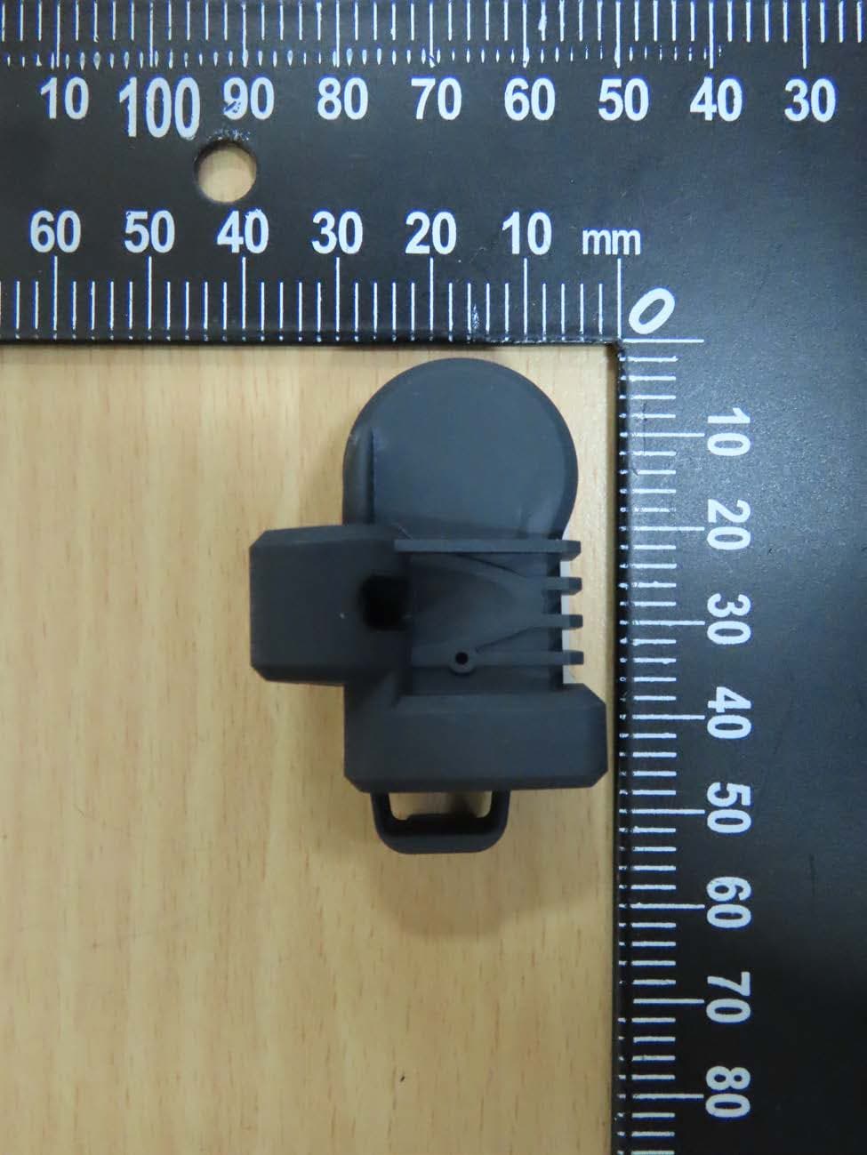
HQXRSI30
Sep 02, 2024TPMS
Equipment Class
DSC - Part 15 Security/Remote Control Transmitter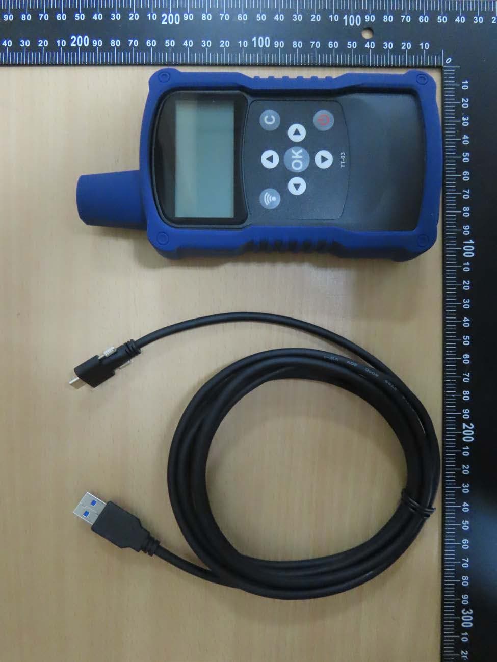
HQXTT03
Jul 01, 2024TPMS Trigger
Equipment Class
DCD - Part 15 Low Power Transmitter Below 1705 kHz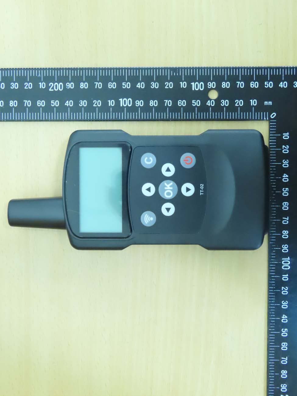
HQXTT02
May 27, 2020TPMS Trigger
Equipment Class
DCD - Part 15 Low Power Transmitter Below 1705 kHz