HQXSAXM105A127MHz Wireless Mouse
Sysgration Ltd.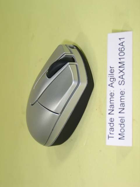
Click to zoom
Application Details
- Equipment Class
- DXX - Part 15 Low Power Communication Device Transmitter
- Date of Grant
- Mar 28, 2005
- Application Purpose
- Original Equipment
- Date of Application
- Mar 28, 2005
- Equipment Note
- 27MHz Wireless Mouse
- Frequency Range
- 27.04500000 - 27.04500000
- Company
- Sysgration Ltd.
- Country
- Taiwan
Documents & Files
Document Text
Text extracted from the exhibit documents filed with the FCC. Open a document above to read the original.
Users Manual
SAXM105A1 Wireless Optical Mouse User Manual SAXM105A1 User’s Guide 1. Connecting with Computer: The first time you take out this mouse and receiver from the packin g, Factory Preset ID enables Plug and Play function. Plug the Receiver into PC USB Port . Under Win2000 or higher , wait for the OS to detect the RF device. Under Win98 or lower installation of driver for the device is necessary. Insert the batteries into the mouse and move it for a while , then it starts working . 2. Inserting Batteries: A. Push the battery cover compartment backwards and open it . B. Insert 2 AAA batteries Into compartment with correct orientation . C. Slide the battery cover into the compartment and close the cover . 3. ID Link: When Factory ID has been changed or wish to be changed , link ID as below : A. Press the ID button on the bottom of the mouse . The led on it starts blinking . B. Press the ID button on the top of the receiver. The led on it blinks fastly and link is OK . !ID linking should be completed within 10 seconds or connection would be failed 4. Low Battery Alert: When batteries power drops down to 2V, the alert Led on the left side of the mouse starts flashing. Please replace new batteries . Alert Led 6. Power Saving Mode: A. Suspend Mode : Keep mouse stationary for 10 minutes, mouse will be automatically set to Suspend Mode. Press left button to wake up the mouse again. B. Power Off Mode : When you wish to set the mouse to power off mode, press mouse ID for 3 seconds . The Optical Led will flash once and then fade out showing mouse power is already off. Press ID switch for waking up again . 7. Trouble Shooting: A. When mouse doesn’t respond, check the battery power status, and make sure Battery Power is full. B. Check the battery pole if the optical Led is still off after inserting batteries. C. If battery power is full and led is normal yet mouse still won’t work , do ID Linking to set up connection again. D. Ask for maintenance solution from your retailer and engineer if upper trouble shooting would not work. Personally taking apart after trouble happened is prohibited. FCC Note : This equipment has been tested and comply with the limits for a class B digital device, pursuant to Part 15 of the FCC Rules. These limits are designed to provide reas onable protection. This equipment generates, uses and can radiated radio frequency energy and, if not installed and used in accordance with the instructions, may cause harmful interference to radio comm unications. However, there is no guarantee that interference will not occur in a particular installation if this equipment does cause harmful inte rference to radio or television reception, which can be determined by turning the equipment off and on, the user is encouraged to try to correct the interference by one or more of the following measures: -Reorient or relocate the receiving antenna. -Increase the separation between the equipment and receiver. -Connect the equipment into an outlet on a circuit different from that to which the receiver is connected. -Consult the dealer or an experienced radio/TV technician for help. Changes or modifications not expressly approved by the party responsible for compliance could void the user’s authority to operate the equipment. The antenna(s) used for this transmitter must not be co-located or operating in conjunction with any other antenna or transmitter FCC ID : HQXSAXM105A1
Block Diagram
SAXM105A1 Wireless Optical mouse Block Diagram of TX Sdio / Sclk TX:27.045MHz ANT Z1,Z2 +3.0V Crystal(27.042MHz) R, L, M Mouse: When Power on, Input Voltage is first ensured to 3.0V by DC to DC convertor, and Power Reset is done. Random Mouse ID can be sent then. After detecting motion signals from X/Y/Z Axis and also signals from button switches, controller would encode the signals and later modulate to 27.092MHz radio frequency and transmit to the air. ID SW MICROCONTROLLER OPTICAL DETECT ENCODER DETECT BUTTON DETECT BATTERY LOW DETECT TX RF MODULE BATTERY DC/DC CONVERTER Crystal 76.8KHz Block Diagram of Receiver 26.59MHz 27.045MHz ID SW PC Demodulation Mouse Micro-controller 6.0MHz For Mouse Led Indicator USB/PS2 Port EEPROM
Cover Letter(s)
American Telecommunications Certification Body Inc. 6731 Whittier Ave, McLean, VA 22101 March 22, 2005 RE: FCC ID: HQXSAXM105A1 Attention: Yvette Chen I have a few comments on this Application. Please note that further comments may arise in response to answers provided to the questions below. 1. Please note that you have not included the frequency of the device on the 731 form. Please provide this information on the 731 form. 2. Please note that your request for confidentiality letter is confusing. You state that you are not seeking confidentiality for any exhibits. Why was a request for confidentiality letter provided? If confidentiality is requested for certain exhibits, please provide a request that specifically mentions the exhibits requested to be confidential. Please note that only the following exhibits may be held confidential for this type device: schematics, block diagrams, operational descriptions, parts lists is provided. 3. Please complete section 4a of the 731 (equipment code). The equipment code for this device would probably be DXX. Please clarify. 4. Please provide a more complete block diagram of the transmitter section itself. 5. Please verify that the USB dongle is a receiver only and does not transmit. 6. Please note that the user’s manual is not an appropriate operational description. Please provide an adequate operational description that is in accordance with 2.1033 of the FCC rules. Such an operational description must contain, “a brief description of the circuit functions of the device along with a statement describing how the device operates. This statement should contain a description of the ground system and antenna, if any, used with the device.” This operational description would describe how the transmitter functions and also describe if the USB dongle is a receive only device etc. 7. Please note that the test setup photos are not in accordance with ANSI C63.42003 (i.e. 10 cm separation distances between devices not met). Please note that as the EUT is the mouse transmitter, it should be tested as a stand alone transmitter. However, when tested as part of a system, then ANSI C63.4 2003 must be followed. 8. Please note that 15.227 is a field strength measurement using an average detector and is not an ERP/EIRP limit. The field strength limit for this type device is 80dBuV/m at 3 meters. Please also note that test report and testing for FCC compliance must be in accordance with ANSI C63.4 2003. Please note that ANSI C63.4 3003 section 10.1.1 (Reports) states, “In addition to this standard, any other standards to which the EUT was tested shall be clearly described in the test report.” Please also note that the report provided is a CE compliance report and does not properly address FCC rules and regulations for this device as required by ANSI C63.4. Please also note that it is not possible from the data in the report to determine if the values given as “Reading Data dBm” includes the necessary receive antenna factors, site cable factors or other required factors. Because of this ambiguity and because the CE report is not in accordance with ANSI C63.4 2003 this is not an appropriate FCC compliance report and does clearly show compliance to the required standards and limits. Please provide a report in accordance with FCC part 15.227 and ANSI C63.4 2003. Please include all necessary field strength readings which include all necessary factors and please include a sample formula showing how all factors are accounted for. 9. Please provide a test report which properly addresses 47CFR rules and limits for spurious emissions. Please test the device for compliance to FCC rules. 10. Please provide the schematics for the transmitter as required by 2.1033(a)(5) of the FCC rules. z Page 2 March 22, 2005 Dennis Ward mailto:[email protected] The items indicated above must be submitted before processing can continue on the above referenced application. Failure to provide the requested information may result in application termination. Correspondence should be considered part of the permanent submission and may be viewed from the Internet after a Grant of Equipment Authorization is issued. Please do not respond to this correspondence using the email reply button. In order for your response to be processed expeditiously, you must submit your documents through the AmericanTCB.com website. Also, please note that partial responses increase processing time and should not be submitted. Any questions about the content of this correspondence should be directed to the sender.
Cover Letter(s)
FCC ID: HQXSAXM105A1 ATTN: Mr. Dennis Ward RE: FCC Comments I have a few comments on this Application. Please note that further comments may arise in response to answers provided to the questions below. 1. Please note that you have not included the frequency of the device on the 731 form. Please provide this information on the 731 form. Pls see the revise 731 form. ( file name: Revise – FCC 731 form) 2. Please note that your request for confidentiality letter is confusing. You state that you are not seeking confidentiality for any exhibits. Why was a request for confidentiality letter provided? It should be an authorization letter, not a confidentiality letter. (file name: Revise FCC – authorization letter) Thus, there is no confidentiality towards the following items. If confidentiality is requested for certain exhibits, please provide a request that specifically mentions the exhibits requested to be confidential. Please note that only the following exhibits may be held confidential for this type device: schematics, block diagrams, operational descriptions, parts lists is provided. 3. Please complete section 4a of the 731 (equipment code). The equipment code for this device would probably be DXX. Please clarify. Yes, it is DXX and please the revise 731 form. 4. Please provide a more complete block diagram of the transmitter section itself. Pls see the file (file name: Revise Block – TX ) 5. Please verify that the USB dongle is a receiver only and does not transmit. Pls see the file (file name: Revise Block – RX) 6. Please note that the user’s manual is not an appropriate operational description. Please provide an adequate operational description that is in accordance with 2.1033 of the FCC rules. Such an operational description must contain, “a brief description of the circuit functions of the device along with a statement describing how the device operates. This statement should contain a description of the ground system and antenna, if any, used with the device.” This operational description would describe how the transmitter functions and also describe if the USB dongle is a receive only device etc. 7. Please note that the test setup photos are not in accordance with ANSI C63.42003 (i.e. 10 cm separation distances between devices not met). Please note that as the EUT is the mouse transmitter, it should be tested as a stand alone transmitter. However, when tested as part of a system, then ANSI C63.4 2003 must be followed. Pls see the revise test report (file name: Revise FCC Test Report) 8. Please note that 15.227 is a field strength measurement using an average detector and is not an ERP/EIRP limit. The field strength limit for this type device is 80dBuV/m at 3 meters. Please also note that test report and testing for FCC compliance must be in accordance with ANSI C63.4 2003. Please note that ANSI C63.4 3003 section 10.1.1 (Reports) states, “In addition to this standard, any other standards to which the EUT was tested shall be clearly described in the test report.” Please also note that the report provided is a CE compliance report and does not properly address FCC rules and regulations for this device as required by ANSI C63.4. Please also note that it is not possible from the data in the report to determine if the values given as “Reading Data dBm” includes the necessary receive antenna factors, site cable factors or other required factors. Because of this ambiguity and because the CE report is not in accordance with ANSI C63.4 2003 this is not an appropriate FCC compliance report and does clearly show compliance to the required standards and limits. Please provide a report in accordance with FCC part 15.227 and ANSI C63.4 2003. Please include all necessary field strength readings which include all necessary factors and please include a sample formula showing how all factors are accounted for. Pls see the revise test report (file name: Revise FCC Test Report) 9. Please provide a test report which properly addresses 47CFR rules and limits for spurious emissions. Please test the device for compliance to FCC rules. Pls see the revise test report (file name: Revise FCC Test Report) 10. Please provide the schematics for the transmitter as required by 2.1033(a)(5) of the FCC rules. Pls see the file name: Revise Schematics
External Photos
FCC Test Report Report No.:RF-J19-0412-197 CENTRAL RESEARCH TECHNOLOGY CO. Page : A2-1 No. 11, Lane 41, Fushuen St., Jungshan Chiu, Taipei, Taiwan, 104, R.O.C. TEL. : 886-2-25984542 FAX. : 886-2-25984546 Attachment 2 External Photographs of EUT FCC Test Report Report No.:RF-J19-0412-197 CENTRAL RESEARCH TECHNOLOGY CO. Page : A2-1 No. 11, Lane 41, Fushuen St., Jungshan Chiu, Taipei, Taiwan, 104, R.O.C. TEL. : 886-2-25984542 FAX. : 886-2-25984546 Model No. : SAXM105A1 FCC Test Report Report No.:RF-J19-0412-197 CENTRAL RESEARCH TECHNOLOGY CO. Page : A2-2 No. 11, Lane 41, Fushuen St., Jungshan Chiu, Taipei, Taiwan, 104, R.O.C. TEL. : 886-2-25984542 FAX. : 886-2-25984546 FCC Test Report Report No.:RF-J19-0412-197 CENTRAL RESEARCH TECHNOLOGY CO. Page : A2-3 No. 11, Lane 41, Fushuen St., Jungshan Chiu, Taipei, Taiwan, 104, R.O.C. TEL. : 886-2-25984542 FAX. : 886-2-25984546 FCC Test Report Report No.:RF-J19-0412-197 CENTRAL RESEARCH TECHNOLOGY CO. Page : A2-4 No. 11, Lane 41, Fushuen St., Jungshan Chiu, Taipei, Taiwan, 104, R.O.C. TEL. : 886-2-25984542 FAX. : 886-2-25984546 Model No. : SAXM026A1 FCC Test Report Report No.:RF-J19-0412-197 CENTRAL RESEARCH TECHNOLOGY CO. Page : A2-5 No. 11, Lane 41, Fushuen St., Jungshan Chiu, Taipei, Taiwan, 104, R.O.C. TEL. : 886-2-25984542 FAX. : 886-2-25984546 FCC Test Report Report No.:RF-J19-0412-197 CENTRAL RESEARCH TECHNOLOGY CO. Page : A2-6 No. 11, Lane 41, Fushuen St., Jungshan Chiu, Taipei, Taiwan, 104, R.O.C. TEL. : 886-2-25984542 FAX. : 886-2-25984546 FCC Test Report Report No.:RF-J19-0412-197 CENTRAL RESEARCH TECHNOLOGY CO. Page : A2-7 No. 11, Lane 41, Fushuen St., Jungshan Chiu, Taipei, Taiwan, 104, R.O.C. TEL. : 886-2-25984542 FAX. : 886-2-25984546 Model No. : SAXM037A1 FCC Test Report Report No.:RF-J19-0412-197 CENTRAL RESEARCH TECHNOLOGY CO. Page : A2-8 No. 11, Lane 41, Fushuen St., Jungshan Chiu, Taipei, Taiwan, 104, R.O.C. TEL. : 886-2-25984542 FAX. : 886-2-25984546 FCC Test Report Report No.:RF-J19-0412-197 CENTRAL RESEARCH TECHNOLOGY CO. Page : A2-9 No. 11, Lane 41, Fushuen St., Jungshan Chiu, Taipei, Taiwan, 104, R.O.C. TEL. : 886-2-25984542 FAX. : 886-2-25984546 FCC Test Report Report No.:RF-J19-0412-197 CENTRAL RESEARCH TECHNOLOGY CO. Page : A2-10 No. 11, Lane 41, Fushuen St., Jungshan Chiu, Taipei, Taiwan, 104, R.O.C. TEL. : 886-2-25984542 FAX. : 886-2-25984546 Model No. : SAXM106A1 FCC Test Report Report No.:RF-J19-0412-197 CENTRAL RESEARCH TECHNOLOGY CO. Page : A2-11 No. 11, Lane 41, Fushuen St., Jungshan Chiu, Taipei, Taiwan, 104, R.O.C. TEL. : 886-2-25984542 FAX. : 886-2-25984546 FCC Test Report Report No.:RF-J19-0412-197 CENTRAL RESEARCH TECHNOLOGY CO. Page : A2-12 No. 11, Lane 41, Fushuen St., Jungshan Chiu, Taipei, Taiwan, 104, R.O.C. TEL. : 886-2-25984542 FAX. : 886-2-25984546
ID Label/Location Info
SAGM105A1 Label
Internal Photos
FCC Test Report Report No.:RF-J19-0412-197 CENTRAL RESEARCH TECHNOLOGY CO. No. 11, Lane 41, Fushuen St., Jungshan Chiu, Taipei, Taiwan, 104, R.O.C. Page : A3- TEL. : 886-2-25984542 FAX. : 886-2-25984546 1 Attachment 3 Internal Photographs of EUT FCC Test Report Report No.:RF-J19-0412-197 CENTRAL RESEARCH TECHNOLOGY CO. No. 11, Lane 41, Fushuen St., Jungshan Chiu, Taipei, Taiwan, 104, R.O.C. Page : A3- TEL. : 886-2-25984542 FAX. : 886-2-25984546 2 FCC Test Report Report No.:RF-J19-0412-197 CENTRAL RESEARCH TECHNOLOGY CO. No. 11, Lane 41, Fushuen St., Jungshan Chiu, Taipei, Taiwan, 104, R.O.C. Page : A3- TEL. : 886-2-25984542 FAX. : 886-2-25984546 3 FCC Test Report Report No.:RF-J19-0412-197 CENTRAL RESEARCH TECHNOLOGY CO. No. 11, Lane 41, Fushuen St., Jungshan Chiu, Taipei, Taiwan, 104, R.O.C. Page : A3- TEL. : 886-2-25984542 FAX. : 886-2-25984546 4 FCC Test Report Report No.:RF-J19-0412-197 CENTRAL RESEARCH TECHNOLOGY CO. No. 11, Lane 41, Fushuen St., Jungshan Chiu, Taipei, Taiwan, 104, R.O.C. Page : A3- TEL. : 886-2-25984542 FAX. : 886-2-25984546 5
Operational Description
FCC ID: HQXSAXM105A1 Operational Description 1. The transmitter of the EUT (WIRELESS OPTICAL MOUSE) is powered by 3V Batteries. 2. The type of antenna is PCB antenna. 3. The output power of this device is very low. Thus, under normal use condition, the transmitter and the receiver are fairly close. Hence, high Field Strength is not necessary and not allowed due to the interference.
Schematics
AA A A -. Sensor Angle 90 = Add Capacitor 10nF-. Sensor Angle 270 = GND PCBANT -. Sensor Angle 0 = VDD *. Note68k-->Varible Resistor (VDD Voltage 3.7V) *. Note : Sensor degree selection (PIN NO=22) 00 ATA1180XC + MA6223_Q17K MOUSE angle option A4 11 Monday, March 15, 2004 TitleSize Document Number Rev Date: Sheet of C14 104 C15 470uF R9 5.6K C13 104 C1824p C12 22p C16 220uF C433p WH1 M_WHEEL 123 C733p C11 22p Q1KSC945-Y R3 180k MB1 1 2 D1 1N5817 X1 76.8k L1 150uH C51p C2104 L3 0.82uH C622p R1 1.2M C17 104 LB1 1 2 L21.8uH R2 680k C875p RB1 1 2 SW2 1 2 R7 220k X2 27.142M C1024p SNS1 ATA1160XC 123456789 101112 13141516171819202122232425 26 NRESETDVDDXY_LEDDGNDZ2INZ1INPDTXDORFOORFINRFOUTLB MB RB VDD OSC2OSC1 VL DCVR SVDIN TXCB TYPESEL AGND AVDD a c Q2A733-Y R5 10M R4 * 68k C10.22uF R8 10k R6 47 BAT- BAT+ SELECTE_OPTION 1 2 34 ABCD 4 3 2 1 D CBA Title Number Revision Size A4 Date: 29-Oct-2003 Sheet of File: H:\Mod\A5\EMC\0301011b1.ddb Drawn By: C1104 LED13*3 R310KR2 560 X16.0M S 5 V 1 D- 2 D+ 3 G 4 USB Connect CN1CN-USB CS 1 SK 2 DI 3 DO 4 GND 5 NC 6 NC 7 VCC 8 U3 93LC46A C4 33PC3 33P SWID Q4 2N3906 R4100 C1422P C1315P C11 104C10 104C12 104 R84.7K C927P C28 + C5 100uF R92.7K X226.59M C16100P QUAD 8 DEC2 7 DEC1 6 IFI 5 VCC 4 MBCO 3 OSCE 2 OSCB 1 AUTO 9 FI 10 FO 11 SQI 12 SCAN 13 MUTE 14 GND 15 MOCI 16 U1MC3361_1 CH_CHG 7 RXCB 6 EECK 5 DATA 4 EECS 3 XDLED 2 VSS 1 RFENL 8 NRZIN 9 TEST 10 OSC0 11 OSC1 12 VD3 13 VDD 16 D+ 14 D- 15 U2MA6162_25 CH_ID VCC VDD VDD VDD EP_CS EP_CS EP_SK EP_SK EP_DIO EP_DIO VDD C17100P C15102 JP_GNDJAMPER 2 345 1 FIL1455K C2104 R73.3K C7 103 C8 104 R6100K Q13904 D11N4148 R5 27K C6104 C1818P R110M R10 330 C191000P RJ RJ3? RJ2RES1 + C20100uF DRAWN CHECKED APPORVED BY: BY: BY: C22 2.2uF0805 c 3 B 2 1 1 DCJACKDC JACK D2D-4148 LED23*3 R2 560
Test Report
FCC Test Report Report No.:RF-J19-0412-197 CENTRAL RESEARCH TECHNOLOGY CO. Page : 1 No. 11, Lane 41, Fushuen St., Jungshan Chiu, Taipei, Taiwan, 104, R.O.C. TEL. : 886-2-25984542 FAX. : 886-2-25984546 FCC Test Report E.U.T. : Wireless Optical Mouse Trade Name : Agiler Model : SAXM105A1, SAXM026A1, SAXM037A1 , SAXM106A1 FCC ID : HQXSAXM105A1 Report No. : RF-J19-0412-197 Date of Report : December 24, 2004 Prepared for Sysgration Ltd. 10F1.,No.868-3,Chung Cheng Rd.,Chung Ho,Taipei (235),Taiwan,R.O.C Prepared by Central Research Technology Co. EMC Test Laboratory No.11, Lane41, Fushuen St., Jungshan Chiu, Taipei, Taiwan, 104, R.O.C. NVLAP LAB CODE 200575-0 This report shall not be reproduced, except in full, without the written approval of Central Research Technology Co.. It may be duplicated completely in its entirely for legal use with the permission of the applicant. It should not be used to claim product endorsement by CNLA, NVLAP or any U.S. government agency. The test result in the report applies only to the sample tested. Total : 20 Pages 0905 ILAC MRA FCC Test Report Report No.:RF-J19-0412-197 CENTRAL RESEARCH TECHNOLOGY CO. Page : 2 No. 11, Lane 41, Fushuen St., Jungshan Chiu, Taipei, Taiwan, 104, R.O.C. TEL. : 886-2-25984542 FAX. : 886-2-25984546 Certification of Compliance E.U.T. : Wireless Optical Mouse Trade Name : Agiler Model : SAXM105A1, SAXM026A1, SAXM037A1 ,SAXM106A1 FCC ID : HQXSAXM105A1 Manufacturer : Shanghai Sysgration Industrial Co.Ltd Applicant : Sysgration Ltd. Address :10F1.,No.868-3,Chung Cheng Rd.,Chung Ho,Taipei (235),Taiwan,R.O.C Arrival of Sample(s) : December 22, 2004 Date of Test : December 23, 2004 Applicable Standards : 47 CFR part 15, Subpart C Deviation : N/A Condition of Test Sample : Prototype We, Central Research Technology Co., hereby certify that one sample of the designated product was tested in our facility during the period mentioned above. The test records, data evaluation and Equipment Under Test (EUT) configurations shown in the present report are true and accurate representation of the measurements of the sample’s RF characteristics under the conditions herein specified. The test results show that the EUT as described in the present report is in compliance with the requirements set forth in the standards mentioned above and apply to the tested sample identified in the present report only. The test report shall not be reproduced, except in its entirety, without the written approval of Central Research Technology Co. FCC Test Report Report No.:RF-J19-0412-197 CENTRAL RESEARCH TECHNOLOGY CO. Page : 3 No. 11, Lane 41, Fushuen St., Jungshan Chiu, Taipei, Taiwan, 104, R.O.C. TEL. : 886-2-25984542 FAX. : 886-2-25984546 Contents 1 General Description .......................................................................... 4 1.1 GENERAL DESCRIPTION OF EUT............................................................................................................4 1.2 CHARACTERISTIC OF E.U.T....................................................................................................................4 1.3 TEST METHODOLOGY............................................................................................................................4 1.4 REQUIREMENT FOR COMPLIANCE...........................................................................................................5 1.5 THE SUPPORT UNITS.............................................................................................................................7 1.6 LAYOUT OF SETUP................................................................................................................................8 1.7 TEST FACILITY......................................................................................................................................9 1.8 MEASUREMENT UNCERTAINTY...............................................................................................................9 2 Field Strength of fundamental....................................................... 10 2.1 APPLIED STANDARD............................................................................................................................10 2.2 MEASUREMENT PROCEDURE...............................................................................................................10 2.3 TEST CONFIGURATION......................................................................................................................... 11 2.4 TEST INSTRUMENTS.............................................................................................................................12 2.5 TEST DATA.........................................................................................................................................13 3 Radiated Emission.......................................................................... 15 3.1 APPLIED STANDARD............................................................................................................................15 3.2 MEASUREMENT PROCEDURE...............................................................................................................16 3.3 TEST CONFIGURATION.........................................................................................................................17 3.4 TEST INSTRUMENTS.............................................................................................................................18 3.5 TEST DATA.........................................................................................................................................19 Attachment 1 – Photographs of the Test Configurations Attachment 2 – External Photographs of EUT Attachment 3 – Internal Photographs of EUT FCC Test Report Report No.:RF-J19-0412-197 CENTRAL RESEARCH TECHNOLOGY CO. Page : 4 No. 11, Lane 41, Fushuen St., Jungshan Chiu, Taipei, Taiwan, 104, R.O.C. TEL. : 886-2-25984542 FAX. : 886-2-25984546 1 General Description 1.1 Genera…
Text truncated - open the document above for the full version.
Test Setup Photos
FCC Test Report Report No.:RF-J19-0412-197 CENTRAL RESEARCH TECHNOLOGY CO. Page : A1-1 No. 11, Lane 41, Fushuen St., Jungshan Chiu, Taipei, Taiwan, 104, R.O.C. TEL. : 886-2-25984542 FAX. : 886-2-25984546 Attachment 1 Photographs of the Test Configurations FCC Test Report Report No.:RF-J19-0412-197 CENTRAL RESEARCH TECHNOLOGY CO. Page : A1-1 No. 11, Lane 41, Fushuen St., Jungshan Chiu, Taipei, Taiwan, 104, R.O.C. TEL. : 886-2-25984542 FAX. : 886-2-25984546 Radiated Emission Measurement 27MHz~30MHz FCC Test Report Report No.:RF-J19-0412-197 CENTRAL RESEARCH TECHNOLOGY CO. Page : A1-2 No. 11, Lane 41, Fushuen St., Jungshan Chiu, Taipei, Taiwan, 104, R.O.C. TEL. : 886-2-25984542 FAX. : 886-2-25984546 FCC Test Report Report No.:RF-J19-0412-197 CENTRAL RESEARCH TECHNOLOGY CO. Page : A1-3 No. 11, Lane 41, Fushuen St., Jungshan Chiu, Taipei, Taiwan, 104, R.O.C. TEL. : 886-2-25984542 FAX. : 886-2-25984546 30MHz~300MHz FCC Test Report Report No.:RF-J19-0412-197 CENTRAL RESEARCH TECHNOLOGY CO. Page : A1-4 No. 11, Lane 41, Fushuen St., Jungshan Chiu, Taipei, Taiwan, 104, R.O.C. TEL. : 886-2-25984542 FAX. : 886-2-25984546
Contact Information
Applicant
Poll Chang(Manager)
Technical Contact
Central Research Technology Co.Sam Chien
No.11, Ln.41, Fushuen St., · Taipei · Taiwan
Test Firm
Central Research Technology Co.Tsun-Yu Shih
Technical Specifications
| # | Rule Parts | Frequency Range | Power Output |
|---|---|---|---|
| 1 | 15C | 27.045 MHz - 27.045 MHz | - |
Other Applications from Sysgration Ltd.
HQXSWA02
Jun 03, 2026TPMS
Equipment Class
DSR - Part 15 Remote Control/Security Device Transceiver
HQXBSI1505
Dec 02, 2025TPMS-VALVE ASSY, BLE
Equipment Class
DTS - Digital Transmission System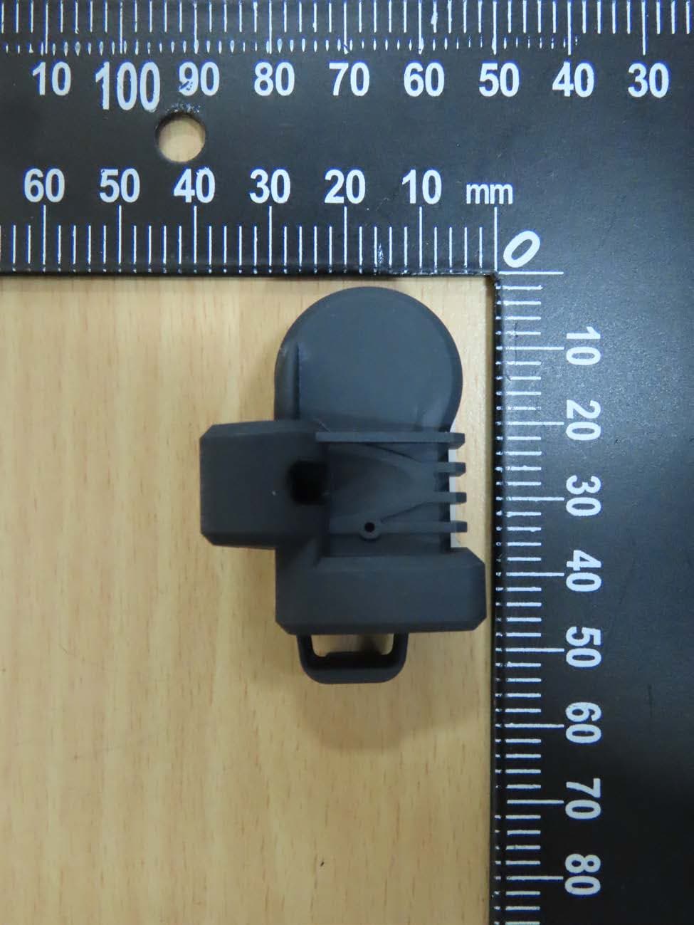
HQXRSI30
Sep 02, 2024TPMS
Equipment Class
DSC - Part 15 Security/Remote Control Transmitter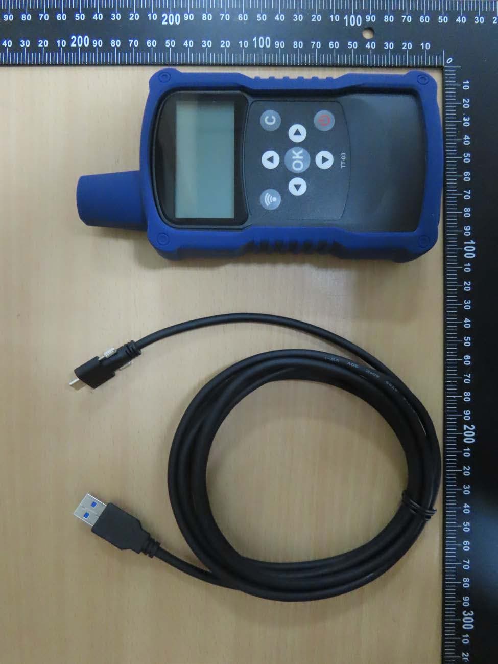
HQXTT03
Jul 01, 2024TPMS Trigger
Equipment Class
DCD - Part 15 Low Power Transmitter Below 1705 kHz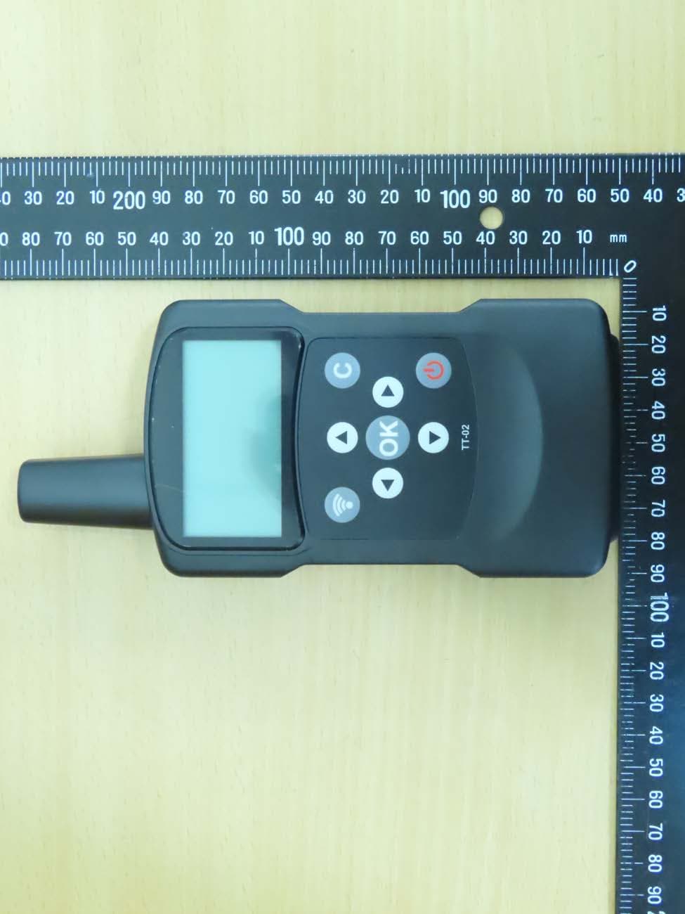
HQXTT02
May 27, 2020TPMS Trigger
Equipment Class
DCD - Part 15 Low Power Transmitter Below 1705 kHz