HQXTA84Voice Dongle
Sysgration Ltd.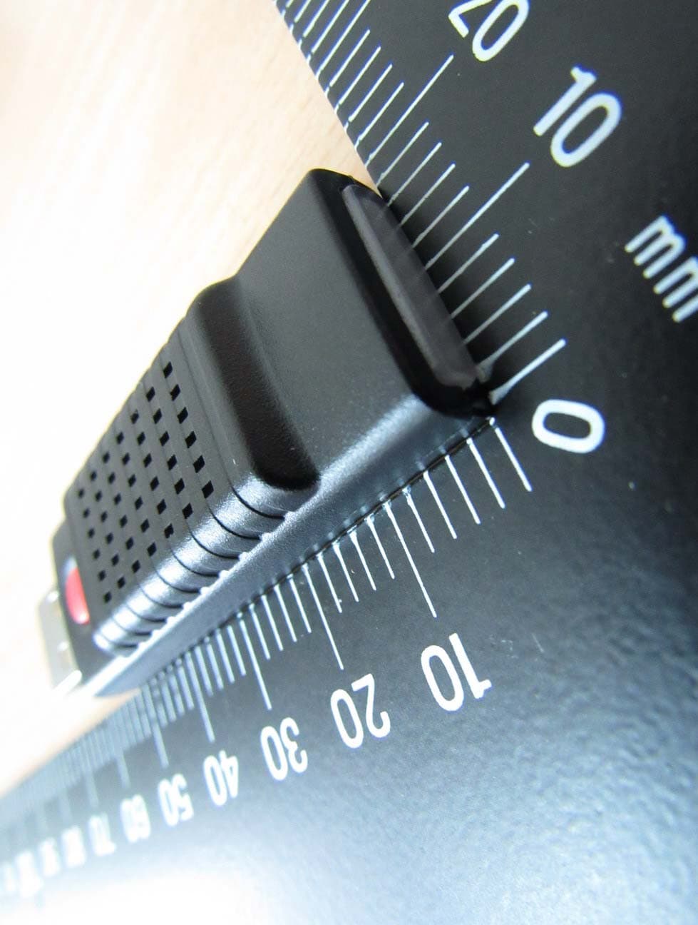
Click to zoom
Application Details
- Equipment Class
- DTS - Digital Transmission System
- Date of Grant
- Sep 27, 2015
- Application Purpose
- Original Equipment
- Date of Application
- Sep 27, 2015
- Equipment Note
- Voice Dongle
- Frequency Range
- 2402.00000000 - 2480.00000000
- Company
- Sysgration Ltd.
- Country
- Taiwan
Documents & Files
Document Text
Text extracted from the exhibit documents filed with the FCC. Open a document above to read the original.
Users Manual
1 Voice Dongle User Manual TA84 2 Table of Contents 1. VOICE DONGLE SPECIFICATION ......................................................................................... 3 2. INSTALLATION STEPS .............................................................................................................. 3 3. VOICE DONGLE SETTING ....................................................................................................... 4 4. WARRANTY POLICY ................................................................................................................. 5 1. Voice Dongle Specification Operating Voltage Operating Humidity Operating Current Storage Temperature Operating Temperature Sound Pressure (min.) Operating Frequency Transmission Power Weight Operating Voltage 2. Installation Steps 3 Voice Dongle Specification 95 % MAX <900 mA at DC 5V -40°C to 85 °C -20°C to 85 °C 80dB@30cm 2.4GHz 4 dBm MAX 10 ± 1 g 5V 3. Voice Dongle Setting iOS version Pic 1 Pic Pic 3 Pic Voice Dongle Setting: 1. Press the red voice dongle button for 1.5 seconds. When you hear “beep,” you will go into the Bluetooth pairing mode (LED : flicker of Red and Blue light ). (Pic 2) 2. Enter menu ->click ”Dongle” function “TPMS_Dongle_sn Connected” will be shown in blue color. (Pic 3) 3. iOS version: The APP will automatically download th completed.” You can start using after “Voice dongle Setting OK” is displayed. Android version: Please click write. The APP will automatically download the settings when you hear “Setup completed.” When “Dongle Setting OK” is displayed, you can start using. Mute/ Un-Mute: Press the red button to mute. Press the red button again or the mute function to cancel automatically. 4 Android version Pic 2 Pic 4 Pic 1 Pic 3 Press the red voice dongle button for 1.5 seconds. When you hear “beep,” you will go into the Bluetooth pairing mode (LED : flicker of Red and Blue light ). (Pic 2) >click ”Dongle” function ->click “TPMS_Dongle_sn” (random serial number), “TPMS_Dongle_sn Connected” will be shown in blue color. (Pic 3) automatically download the settings when you hear “Setup completed.” You can start using after “Voice dongle Setting OK” is displayed. Android version: Please click write. The APP will automatically download the settings when you hear “Setup completed.” When “Dongle Setting OK” is displayed, you can start using. Mute: Press the red button to mute. Press the red button again or wait 10 minutes for the mute function to cancel automatically. Pic 2 Pic 4 Press the red voice dongle button for 1.5 seconds. When you hear “beep,” you will go into the >click “TPMS_Dongle_sn” (random serial number), e settings when you hear “Setup completed.” You can start using after “Voice dongle Setting OK” is displayed. Android version: Please click write. The APP will automatically download the settings when you hear “Setup completed.” When “Dongle Setting OK” is displayed, you can start using. wait 10 minutes for 5 4. Warranty Policy Thank you for buying this product and giving us support. From the date of purchase, we provide a one-year warranty for the product, protecting the client’s interest by providing product quality assurance. During the warranty period, under normal operation and in the event of a faulty product, the company is willing to repair the faulty product or have it replaced, enabling you to get the guarantee and demonstrating the company's responsible attitude toward products. But the product warranty must meet the following conditions : 1. Defective products need to be provided to local dealer to confirm purchase date and cause of defect. 2. Products must be operated correctly, as indicated in the user manual. 3. Product has not been disassembled by yourself. 4. The main cause of product failure is due to manufacture issues. Disclaimer: This product is only to be used as precautionary warning and provides to user as a convenient secondary safety equipment. Please follow the standard installation procedures or ask a qualified tire shop to install the product. If the tire has been damaged or traffic accident resulting from improper driving behavior occurs, the company will not be responsible for any civil or criminal liabilities. Other relevant latest information of SYSGRATION TPMS is available at our website ( http://www.sysgration.com/ ) and our Facebook Page (http://www.facebook.com/sysgration) for latest information. Federal Communication Commission Interference Statement This equipment has been tested and found to comply with the limits for a Class B digital device, pursuant to Part 15 of the FCC Rules. These limits are designed to provide reasonable protection against harmful interference in a residential installation. This equipment generates, uses and can radiate radio frequency energy and, if not installed and used in accordance with the instructions, may cause harmful interference to radio communications. However, there is no guarantee that interference will not occur in a particular installation. If this equipment does cause harmful interference to radio or television reception, which can be determined by turning the equipment off and on, the user is encouraged to try to correct the interference by one of the following measures: . Reorient or relocate the receiving antenna. . Increase the separation between the equipment and receiver. . Connect the equipment into an outlet on a circuit different from that to which the receiver is connected. . Consult the dealer or an experienced radio/TV technician for help. FCC Caution: To assure continued compliance, any changes or modifications not expressly approved by the party responsible for compliance could void the user's authority to operate this equipment. (Example - use only shielded interface cables when connecting to computer or peripheral devices). FCC Radiation Exposure Statement This equipment complies with FCC RF radiation exposure limits set forth for an uncontrolled environment. This equipment should be insta…
Text truncated - open the document above for the full version.
External Photos
Registration number: W6M21508-15220-FCC FCC ID: HQXTA84 Worldwide Testing Services(Taiwan) Co., Ltd. Appendix page 2 of 13 External Photos Registration number: W6M21508-15220-FCC FCC ID: HQXTA84 Worldwide Testing Services(Taiwan) Co., Ltd. Appendix page 3 of 13 Registration number: W6M21508-15220-FCC FCC ID: HQXTA84 Worldwide Testing Services(Taiwan) Co., Ltd. Appendix page 4 of 13 Registration number: W6M21508-15220-FCC FCC ID: HQXTA84 Worldwide Testing Services(Taiwan) Co., Ltd. Appendix page 5 of 13
ID Label/Location Info
FCC ID: HQXTA84
Internal Photos
Registration number: W6M21508-15220-FCC FCC ID: HQXTA84 Worldwide Testing Services(Taiwan) Co., Ltd. Appendix page 6 of 13 Internal Photos Registration number: W6M21508-15220-FCC FCC ID: HQXTA84 Worldwide Testing Services(Taiwan) Co., Ltd. Appendix page 7 of 13 Registration number: W6M21508-15220-FCC FCC ID: HQXTA84 Worldwide Testing Services(Taiwan) Co., Ltd. Appendix page 8 of 13 Registration number: W6M21508-15220-FCC FCC ID: HQXTA84 Worldwide Testing Services(Taiwan) Co., Ltd. Appendix page 9 of 13
RF Exposure Info
Registration number: W6M21508-15220-C-1 FCC ID: HQXTA84 Worldwide Testing Services(Taiwan) Co., Ltd. Page 15 of 30 3.2 Equivalent isotropic radiated power FCC Rule: 15.247(b)(3) EIRP = max. conducted output power + antenna gain (Directional gain) EIRP = 3.18 dBm + (2.04 dBi) = 5.22 dBm Limit: EIRP = +36 dBm for Antenna gain <6dBi Test equipment used: ETSTW-RE 055 3.3 RF Exposure Compliance Requirements According to KDB447498 10 D01v05: SAR evaluation, by measurement or numerical simulation, is not required when the corresponding SAR Exclusion Threshold condition, listed below, is satisfied. The enclosure of the device provides ≥ 0.5 cm separation from the antenna elements to significant metal parts of the enclosure to minimize potential perturbations. Frequency Band:2402-2480 MHz Maximum Power fed to Antenna: 3.3266 mW Separation distances: Antenna feed center to metal parts of enclosure: > 5 mm Distance prescribed in user manual: > 5 mm MHz 5 10 15 20 25 mm 2450 10 19 29 38 48 SAR Test Exclusion Threshold (mW) MHz 30 35 40 45 50 mm 2450 57 67 77 86 96 SAR Test Exclusion Threshold (mW) MHz 50 60 70 80 90 100 110120130140150160170 180 190 mm 2450 96 196 296 396496 596 696796896996109611961296 1396 1496 mW
Test Report
of Applicant: Sysgration Ltd. Address: 6F-2.,No.1,Sec.1,Tiding Blvd.,Neihu Dist. Taipei City Taiwan 114 Tested and Prepared by Worldwide Testing Services (Taiwan) Co., Ltd. FCC Registration No.: 930600 Industry Canada filed test laboratory Reg. No. IC 5679A-1, IC 5107A-1 A2LA Accredited No.: 2732.01 Report No.: W6M21508-15220-C-1 6F, NO. 58, LANE 188, RUEY-KUANG RD., NEIHU TAIPEI 114, TAIWAN, R.O.C. TEL: 886-2-66068877 FAX: 886-2-66068879 E-mail: [email protected] FCC PART 15 SUBPART C TEST REPORT for Voice Dongle Model No.: TA84 FCC ID: HQXTA84 Registration number: W6M21508-15220-C-1 FCC ID: HQXTA84 Worldwide Testing Services(Taiwan) Co., Ltd. Page 1 of 30 TABLE OF CONTENTS 1 GENERAL INFORMATION ..........................................................................................................2 1.1 NOTES..........................................................................................................................................2 1.2 TESTING LABORATORY................................................................................................................3 1.2.1 Location ..................................................................................................................................3 1.2.2 Details of accreditation status ................................................................................................3 1.3 DETAILS OF APPROVAL HOLDER...................................................................................................3 1.4 APPLICATION DETAILS.................................................................................................................4 1.5 GENERAL INFORMATION OF TEST ITEM........................................................................................4 1.6 TEST STANDARDS.........................................................................................................................5 2 TECHNICAL TEST .........................................................................................................................6 2.1 S UMMARY OF TEST RESULTS........................................................................................................6 2.2 TEST ENVIRONMENT....................................................................................................................6 2.3 TEST EQUIPMENT LIST.................................................................................................................7 2.4 G ENERAL TEST PROCEDURE........................................................................................................9 3 TEST RESULTS (ENCLOSURE) ................................................................................................11 3.1 PEAK OUTPUT POWER (TRANSMITTER) ......................................................................................12 3.2 E QUIVALENT ISOTROPIC RADIATED POWER................................................................................15 3.3 RF EXPOSURE COMPLIANCE REQUIREMENTS............................................................................15 3.4 TRANSMITTER RADIATED EMISSIONS IN RESTRICTED BANDS....................................................16 3.5 S PURIOUS EMISSIONS (TX) .........................................................................................................17 3.6 R ADIATED EMISSION ON THE BAND EDGE..................................................................................19 3.7 MINIMUM 6 DB BANDWIDTH.....................................................................................................21 3.8 P EAK POWER SPECTRAL DENSITY.............................................................................................24 3.9 RADIATED EMISSION FROM DIGITAL PART................................................................................27 3.10 POWER LINE CONDUCTED EMISSION.........................................................................................28 APPENDIX.............................................................................................................30 Registration number: W6M21508-15220-C-1 FCC ID: HQXTA84 Worldwide Testing Services(Taiwan) Co., Ltd. Page 2 of 30 1 General Information 1.1 Notes The purpose of conformity testing is to increase the probability of adherence to the essential requirements or conformity specifications, as appropriate. The complexity of the technical specifications, however, means that full and thorough testing is impractical for both technical and economic reasons. Furthermore, there is no guarantee that a test sample which has passed all the relevant tests conforms to a specification. Neither is there any guarantee that such a test sample will interwork with other genuinely open systems. The existence of the tests nevertheless provides the confidence that the test sample possesses the qualities as maintained and that is performance generally conforms to representative cases of communications equipment. The test results of this test report relate exclusively to the item tested as specified in 1.5. The test report may only be reproduced or published in full. Reproduction or publication of extracts from the report requires the prior written approval of the Worldwide Testing Services(Taiwan) Co., Ltd. Tester: September 15, 2015 Rick Chen Date WTS-Lab. Name Signature Technical responsibility for area of testing: September 15, 2015 Kevin Wang Date WTS Name Signature Registration number: W6M21508-15220-C-1 FCC ID: HQXTA84 Worldwide Testing Services(Taiwan) Co., Ltd. Page 3 of 30 1.2 Testing laboratory 1.2.1 Location OATS No.5-1, Lishui, Shuang Sing Village, Wanli Dist., New Taipei City 207, Taiwan (R.O.C.) 3 meter semi-anechoic chamber No.35, Aly. 21, Ln. 228, Ankang Rd., Neihu Dist., Taipei City 114, Taiwan (R.O.C.) TEL:886-2-6613-0228 FAX:886-2-2791-5046 Company Worldwide Testing Services(Taiwan) Co., Ltd. 6F, NO. 58, LANE 188, RUEY-KUANG RD. NEIHU, TAIPEI 114, TAIWAN R.O.C. Tel : 886-2-66068877 Fax : 88…
Text truncated - open the document above for the full version.
Test Setup Photos
Registration number: W6M21508-15220-FCC FCC ID: HQXTA84 Worldwide Testing Services(Taiwan) Co., Ltd. Appendix page 10 of 13 Set Up Photo of Radiated Emission EMI Below 1GHz Registration number: W6M21508-15220-FCC FCC ID: HQXTA84 Worldwide Testing Services(Taiwan) Co., Ltd. Appendix page 11 of 13 Above 1GHz Registration number: W6M21508-15220-FCC FCC ID: HQXTA84 Worldwide Testing Services(Taiwan) Co., Ltd. Appendix page 12 of 13 RF Registration number: W6M21508-15220-FCC FCC ID: HQXTA84 Worldwide Testing Services(Taiwan) Co., Ltd. Appendix page 13 of 13 Set Up Photo of Conducted Emission
Contact Information
Applicant
Arthur Dai(Manager)
Technical Contact
Worldwide Testing Services (Taiwan) Co., Ltd.Danny Sung
[email protected]+886-2-6606-8877
6F., No. 58, Lane 188, Ruey Kuand Rd. · Taipei · Taiwan
Test Firm
Worldwide Testing Services (Taiwan) Co., Ltd.Rex Kao
Technical Specifications
| # | Rule Parts | Frequency Range | Power Output |
|---|---|---|---|
| 1 | 15C | 2.40 GHz - 2.48 GHz | 2.08 mW |
Other Applications from Sysgration Ltd.
HQXSWA02
Jun 03, 2026TPMS
Equipment Class
DSR - Part 15 Remote Control/Security Device Transceiver
HQXBSI1505
Dec 02, 2025TPMS-VALVE ASSY, BLE
Equipment Class
DTS - Digital Transmission System
HQXRSI30
Sep 02, 2024TPMS
Equipment Class
DSC - Part 15 Security/Remote Control Transmitter
HQXTT03
Jul 01, 2024TPMS Trigger
Equipment Class
DCD - Part 15 Low Power Transmitter Below 1705 kHz
HQXTT02
May 27, 2020TPMS Trigger
Equipment Class
DCD - Part 15 Low Power Transmitter Below 1705 kHz