HVVAD27WWireless Intercom
Federal Signal Corporation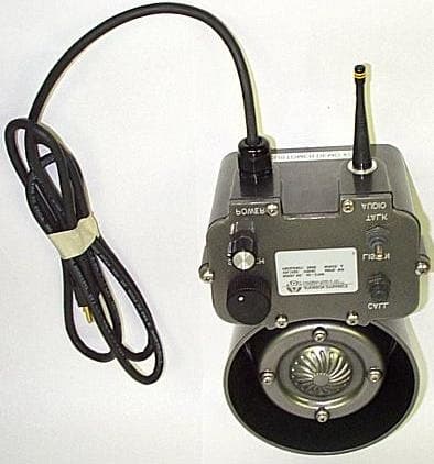
Click to zoom
Application Details
- Equipment Class
- DXT - Part 15 Low Power Transceiver, Rx Verified
- Date of Grant
- May 22, 2002
- Application Purpose
- Original Equipment
- Date of Application
- May 22, 2002
- Equipment Note
- Wireless Intercom
- Frequency Range
- 903.00000000 - 922.00000000
- Company
- Federal Signal Corporation
- Country
- United States
Documents & Files
Document Text
Text extracted from the exhibit documents filed with the FCC. Open a document above to read the original.
Users Manual
Address all communications and shipments to: 2645 Federal Signal Drive University Park, IL 60466-3195 (888)751-1500 Atkinson Dynamics Wireless Intercom Model AD-27W Installation and Service Instructions -1- INSTALLATION AND SERVICE INSTRUCTIONS FOR ATKINSON DYNAMICS WIRELESS HEAVY-DUTY INTERCOMS SAFETY MESSAGE TO INSTALLERS, USERS AND MAINTENANCE PERSONNEL It is important to follow all instructions shipped with this product. This device is to be installed by a trained electrician who is thoroughly familiar with the National Electrical Code and will follow NEC Guidelines as well as local codes. Marine installa- tions shall be in accordance with Title 46, CFR, Parts 110-113. The selection of the mounting location for the device is to be accomplished under the direction of the facilities engineer and the safety engineer. In addition, listed below are some other important safety instructions and precautions you should follow: •This is not a listed safety device and is not intended to be used as such. •Read and understand all instructions before installing or operating this equipment. •Disconnect power before connecting or doing any maintenance on this intercom. •All effective warning speakers produce loud sounds which may cause in certain situations, permanent hearing loss. You should take appropriate precautions such as wearing hearing protection. •After testing is complete, provide a copy of this instruction sheet to all operating personnel. •Establish a procedure to routinely check the intercom installation for integrity and proper operation. Any maintenance must be performed by a trained electrician in accordance with NEC guidelines and local codes. Failure to follow all safety precautions and instructions may result in property damage, serious injury, or death to you or others. A.GENERAL FEATURES. The Atkinson Dynamics wireless intercom is a heavy-duty, 2-way, communications device designed for industrial applications. The nominal operating voltage is 120VAC, 50/60 Hz. A “whip” style 1/4-wave antenna is built into the bottom of each unit. The intercoms operate in the 902-928 MHz band and offer the user eight selectable channels. A 4-position switch, located on the printed circuit board inside the unit, allows the user to select the channel of operation. All units in a system must be set to the same channel of frequency to communicate with each other. Refer to section E for details on setting the channel of operation. The range of the intercom is 500 feet under optimum conditions. The range is dependent on the environment and decreases when obstacles are in the way. Line-of-sight between intercoms will provide the best range. Each unit is equipped with a squelch control knob located on the front cover. A shielded power cord is supplied with each unit. The AC power line is fused with a 1/2-amp, 250- volt type GMC fuse. A description of the available models follows. -2- Basic Model Specifications Model AD-27W Supply Voltage120VAC, 50/60 Hz Audio Power Output (Max.)11.3 Watts Power Consumption (Max.)28.8 Watts Operating Current (nominal)0.240 A Operating Temperature+32°F to 150°F Shipping Weight10 lbs. 11 oz DimensionsSee Figure 2. RatingsUL, cUL, Marine-Listed NEMA-Type 4X (excluding microphone models) Table 1. Additional Model Information Letter GroupFunction/Feature “A”Call button Table 2. CALL BUTTON: “A” Models are equipped with a Call switch. Depressing the call switch transmits an 890Hz tone to all units in the intercom system. CAUTION The call signal is louder than normal voice messages being carried on the line. Do not depress the call switch while carrying on a conversation with someone on the system. This will subject the listener to very loud sound levels. The volume of the call signal is affected by the volume control on the receiving unit, so if volume is turned all the way down at a receiving station, the call signal will not be heard. B.UNPACKING. After unpacking the Atkinson Dynamics Intercom, examine it for damage that may have occurred in transit. If the equipment has been damaged, do not attempt to install or operate it, and file a claim immediately with the carrier stating the extent of the damage. Carefully check all envelopes, shipping labels and tags before removing or destroying them. -3- C.MOUNTING. CAUTION The selection of the mounting location for the device is to be accomplished under the direction of the facilities and the safety engineer. NOTE Intercoms supplied with flexible cords for connection to field wiring are not intended for permanent mounting. The intercom is intended to be mounted on any relatively flat and rigid surface by the two mounting ears on the exterior of the housing. Figure 5 is a dimensional outline drawing showing the proper mounting configuration. The two mounting ears are 13/32" diameter holes spaced 5.68" apart. Hardware for mounting the intercom to the surface shall be provided by the installer. NOTE The unit should be mounted right side up with the antenna pointed down- ward. Failure to do so may void FCC compliance. WARNING This unit is heavy and should be mounted on a rigid surface capable of supporting the weight of the intercom. WARNING For shipboard applications, installations shall be in accordance with the United States Coast Guard, Title 46 CRF, Parts 110-113. D.ELECTRICAL CONNECTIONS. Plug each intercom into a nearby power source. Each unit is equipped with a shielded power cord with a NEMA 5-15P molded plug. See figure 1 for a typical intercom configuration. E.CHANNEL SELECTION. Each unit is factory set to channel 3 (909.37 MHz). To select another channel, it is necessary to reconfigure the 4-position switch located on the printed circuit board inside the unit. To select another channel, perform the following steps; 1.Disconnect power from the unit. 2.Remove and retain the six screws and lock washers from the front cover. 3.Carefully lift the front cover from the housing. 4.Locate the 4-position switch on the circuit board.…
Text truncated - open the document above for the full version.
Block Diagram
ATKINSON DYNAMICS WIRELESS INTERCOM BLOCK/SIGNAL DIAGRAM Receiver Analog Low Pass Expandor Audio Isolation RXM-900-HPII Switch Filter SA575D Transformer 1:1 RSSI (DC) Volume Amp Control Pre-Amp TDA2616 Speaker Antenna Switch 10K Pot. SA630D Channel Select DIP Switch 50Hz to 3KHz 50Hz to 3KHz 50Hz to 3KHz 800Hz to 3500Hz Antenna Port - See Table 1 for frequency Mic. Noise/Canceling Relay Pre-Amp Bias Circuit 800Hz to Transmitter 3500Hz TXM-900-HPII Table 1 Call Circuit Channel Frequency (MHz) 1 903.37 2 906.37 3 907.87 4 909.37 5 912.37 6 915.37 7 919.87 8 921.37 See Table 1 for frequency 50Hz to 25KHz 50Hz to 3KHz 50Hz to 3KHz 50Hz to 3KHz 800Hz to 3500Hz 800Hz to 3500Hz See Table 1 for frequency See Table 1 for frequency 890 Hz DC LinxRF MODULEBLOCK/SIGNALDIAGRAM 575 SE ASHLEY PLACE • GRANTS PASS, OR 97526 PHONE: (800) 736-6677 • FAX: (541) 471-6251 Module Series_____________________Architecture _____________________ Modulation Method ________________Duty Cycle ______________________ Frequency ________________________Overall Accuracy _________________ HP RXM IIDual Conversion Superhet N/A 902-928MHz30ppm This product utilizes a modular hybrid RF stage manufactured by Linx Technologies Inc. The module contains all RF components excepting antennas. While each module is inherently designed to meet or exceed all FCC requirements, external factors such as antenna selection, transmission content, and intended application may affect its use. A block diagram of the mod- ules internal architecture and signal path is shown above. Additional information regarding the use, construction or testing of Linx modules may be obtained by calling (541) 471-6256, from 8-4 PST or addressing a written e-mail request to [email protected]. 18 KHz Active LPF SAW BPF 10.7 MHz BPF10.7 MHz BPF 10.7 MHz FM Discriminator 34.7 MHz BPF LIMITING AMP 868-887 MHz (See Table) VCO 902-928 MHz 915 MHz LNAIF 1 BitPERFECT™ BIT SLICER DATA AUDIO RSSI XTO IF 2 IF AMP PLLμP ChannelFrequency 0868.68 1871.68 2873.18 3874.68 4877.68 5880.68 6885.18 7886.68 LO Frequency Table LinxRF MODULEBLOCK/SIGNALDIAGRAM 575 SE ASHLEY PLACE • GRANTS PASS, OR 97526 PHONE: (800) 736-6677 • FAX: (541) 471-6251 Module Series_____________________Architecture _____________________ Modulation Method ________________Duty Cycle ______________________ Frequency ________________________Overall Accuracy _________________ Occupied Bandwidth _______________________________________________ HP TXM FM/FSK Continuous Carrier 902-928MHz±50KHz 32KHz This product utilizes a modular hybrid RF stage manufactured by Linx Technologies Inc. The module contains all RF components excepting antennas. While each module is inherently designed to meet or exceed all FCC requirements, external factors such as antenna selection, transmission content, and intended application may affect its use. A block diagram of the mod- ules internal architecture and signal path is shown above. Additional information regarding the use, construction or testing of Linx modules may be obtained by calling (541) 471-6256, from 8-4 PST or addressing a written e-mail request to [email protected]. Antenna Port Harmonic Filter Output Amplifier Phase-Locked Loop Microcontroller 12.00 MHz FREF Channel Select Precision 12.00 MHz Crystal Reference VCXO 902-928 MHz (See Table) V.C.O. Modulation Low Pass Filter Modulation In CS2CS1CS0ChannelFrequency 0000903.37 0011906.37 0102907.87 0113909.37 1004912.37 1015915.37 1106919.87 1117921.37 Fundamental Frequency Table ~
External Photos
Authorized Agent: Radiometrics Midwest Corporation (815) 293-0772 – [email protected] External EUT Photographs FCC ID: HVVAD27W
Internal Photos
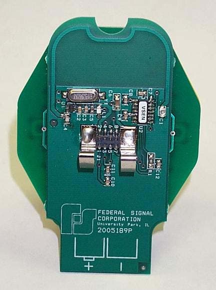
Authorized Agent: Radiometrics Midwest Corporation (815) 293-0772 – [email protected] Internal EUT Photographs FCC ID: HVVAD27W RF boards Authorized Agent: Radiometrics Midwest Corporation (815) 293-0772 – [email protected] EUT OPEN EUT PCB Authorized Agent: Radiometrics Midwest Corporation (815) 293-0772 – [email protected] PCB Foil Side
Operational Description
Authorized Agent: Radiometrics Midwest Corporation (815) 293-0772 – [email protected] Operational Description FCC ID: HVVAD27W The Atkinson Dynamics wireless intercom is a heavy-duty communications device designed for industrial applications. The nominal operating voltage is 120VAC, 50/60 Hz. Each unit is equipped with a power cord that has a NEMA 5-15P molded plug. Each unit has a built-in antenna. The internal circuitry contains an RF transmitter and receiver that operate in the 902-928MHz band. A switch on the circuit board allows the user to select from eight channels. All units are equipped with a squelch adjustment control knob on the front cover. This allows the user to suppress the audio output when noise power that exceeds a predetermined level is present. Each unit is equipped with a power cord that is terminated with a molded plug for 120VAC, 50/60Hz operation. An RF transmitter and receiver, manufactured by Linx Technologies, that operate in the 902-928 MHz band, are located on a printed circuit board inside the unit. A switch on the circuit board allows the user to select from eight channels. A “whip” style ¼-wavelength antenna is threaded into the bottom of each unit. An RG-174 coax cable, attached to the antenna, connects directly to a printed circuit board through a 50-ohm connector. In normal operation, each intercom is in receive, or speaker, mode. The unit acts as a speaker and broadcasts signals generated elsewhere in the intercom system. In this mode of operation, the antenna is connected to the RF receiver through an antenna switch. Each unit has a LISTEN/TALK toggle switch located on the front panel. Depressing the LISTEN/TALK switch places the unit in transmit, or microphone, mode. In this mode, the speaker acts as a microphone allowing the user to broadcast to all other intercoms in the system. The antenna is connected to the transmitter via the antenna switch during transmit mode. Releasing the switch returns the unit to speaker mode. 1 THEORY OF OPERATION Power Supply: The phase side of AC power is brought to a SPST on/off switch on the backside of the volume control potentiometer (pot). The intercom is turned off when the pot is in the CCW position. Fuse F1 is placed in series with the hot side of the power supply for catastrophic overcurrent protection. The output of the transformer is rectified through diodes CR3, CR4, CR5, and CR8 and becomes unregulated DC voltage filtered by C3. CR1 is a 25V zener diode. With the base of the transistor regulated at 25V, the regulated output of the supply at the emitter of Q1 is approximately 24V. R23, R27, and R26 are set to provide an output of 16V from IC1. IC3 provides a regulated output of 5V. Squelch Circuit: The squelch control circuit consists of comparator IC5A, C38, R24, R25, and J3. A 1K-ohm squelch potentiometer (pot) on the front cover is connected to J3 at pins 2 and 3, which places it in series with R24. The negative (-) side of the comparator IC5A-2 is set to a predetermined level (threshold) by adjusting the 1K-ohm squelch pot. When the pot is set at maximum, or 1K ohm, the threshold level at IC5A-2 is 1.6V. When the pot is set a minimum, or 0 ohms, the threshold level at IC5A-2 is 1.0V. The receiver is equipped with an on-board RSSI (Received Signal Strength Indicator) circuit. The RSSI has a voltage range of about 800mV to 2.5V. The positive (+) side of the comparator IC5A-3 is controlled by the RSSI voltage, present at IC10-14. Op amp IC5A compares the RSSI voltage at pin 3 to the threshold voltage at pin 2. The output of the comparator controls analog switch IC6. IC6 either blocks the received audio signal present at receiver IC10-17, or allows it to pass through to the rest of the circuit. When the RSSI voltage exceeds the threshold voltage, the output of the comparator is high. As a result, the analog switch closes and lets the audio signal pass through. When the RSSI voltage is less than the threshold voltage, the comparator output will be low and the analog switch will block the audio signal. Antenna Switch Circuit: Authorized Agent: Radiometrics Midwest Corporation (815) 293-0772 – [email protected] IC13 is a single-pole double-throw wideband RF switch that controls the antenna connection. Pin 4 of IC13 is the enable channel 1 input. When it is high, channel 1 (pin 8) is enabled. When it is low, channel 2 is enabled. Channel 1 is connected to the antenna input on the receiver at IC10-1. Channel 2 is connected to the antenna input on the transmitter at IC7-2. The enable channel input IC13-4 is controlled by the signal out of optocoupler IC15. The output of the optocoupler is connected directly to the POWER DOWN pin on the receiver at IC10-13 and is inverted before being connected to the POWER DOWN pin on the transmitter at IC7-7. This is so the transmitter and receiver are never on at the same time. Diodes CR9 (PTX), CR10 (CALL), and CR13 (PTT) are connected to the input of the optocoupler. If the call button (CALL), talk switch (PTX), or microphone PTT switch is pressed, the optocoupler provides a low output signal. The low signal shuts down the receiver and at the same time, since it is inverted and becomes high, turns on the transmitter. Normally, the unit is in receive (listen) mode and the antenna is connected to the receiver. When CALL, PTX, or PTT is pressed, the unit is placed in transmit (talk) mode and the antenna is connected to the transmitter. “Receive” Audio Path: After audio passes through the analog switch, IC6, it goes through a low pass filter that has a cut-off frequency of 3KHz. The low pass filter contains op amp OP275 (IC12A). After filtering, the received audio signal passes through a noise reduction stage that consists of compandor SA575D (IC9). The compandor boosts the audio signal and compresses any noise. The audio signal then passes through isolation transformer T2 to the high side of the front panel 10K audio taper potentiometer (pot). This pot on the front panel attenu…
Text truncated - open the document above for the full version.
Test Report
Radiometrics Midwest Corporation Page 1 of 1 Electromagnetic Compatibility Test Report Tests Performed on a Federal Signal Corporation Wireless Intercom, Model AD-27W Radiometrics Document RP-4755 Product Detail: FCC ID: HVVAD27W Equipment type: Low Power Transciever Test Standards: US CFR Title 47, Chapter I, FCC Part 15 Subpart C FCC Part 15 CFR Title 47: 2001 Industry Canada RSS-210, Issue 5 as required for Category I Equipment This report concerns: Original Grant for Certification FCC Part 15.249 Tests Performed For: Test Facility: Federal Signal Corporation 18606 S. 81st Street Tinley Park, IL 60477 Radiometrics Midwest Corporation 12 East Devonwood Romeoville, IL 60446 Phone: (815) 293-0772 e-mail: [email protected] Test Date(s): (Month-Day-Year) March 13, 2002 Document RP-4755 Revisions: Rev. Issue Date Affected Pages Revised By Authorized Signature for Revision 0 April 17, 2002 1 May 16, 2002 All Joseph Strzelecki 2 May 17, 2002 All Joseph Strzelecki RADIOMETRICS MIDWEST CORPORATION - EMC Test Report Equipment Tested (Company, Model, Product Name): Document No.: Page: Federal Signal Corporation, AD-27W, Wireless Intercom RP-4755 Rev. 2 2 of 13 Table of Contents 1 ADMINISTRATIVE DATA........................................................................................................................3 2 TEST SUMMARY AND RESULTS.........................................................................................................3 3 EQUIPMENT UNDER TEST (EUT) DETAILS.......................................................................................4 3.1 EUT Description..............................................................................................................................4 3.2 Related Submittals..........................................................................................................................4 4 TESTED SYSTEM DETAILS.................................................................................................................4 4.1 Tested System Configuration..........................................................................................................4 4.2 Equipment Modifications..................................................................................................................4 5 TEST SPECIFICATIONS AND RELATED DOCUMENTS....................................................................4 6 RADIOMETRICS’ TEST FACILITIES.....................................................................................................5 7 DEVIATIONS AND EXCLUSIONS FROM THE TEST SPECIFICATIONS............................................5 8 TEST PROCEDURES...........................................................................................................................5 8.1 Radiated RF Emissions Measurement Procedures.......................................................................5 8.1.1 Field Strength Calculation.........................................................................................................6 8.1.2 Conducted Emission Measurement Procedures.....................................................................7 9 CERTIFICATION....................................................................................................................................7 10 TEST EQUIPMENT TABLE.................................................................................................................7 11 TEST SETUP DOCUMENTATION......................................................................................................8 Figure 1. Configuration of Tested System.........................................................................................8 12 OCCUPIED BANDWIDTH DATA.........................................................................................................9 Figure 2. Occupied Bandwidth Plots.................................................................................................9 13 DETAILED TEST RESULTS.............................................................................................................11 13.1 Radiated Emissions Test Results...............................................................................................11 13.2 Conducted Emission Test Results.............................................................................................13 Notice: This report must not be reproduced (except in full) without the written approval of Radiometrics Midwest Corporation. RADIOMETRICS MIDWEST CORPORATION - EMC Test Report Equipment Tested (Company, Model, Product Name): Document No.: Page: Federal Signal Corporation, AD-27W, Wireless Intercom RP-4755 Rev. 2 3 of 13 1 ADMINISTRATIVE DATA Equipment Under Test: A Federal Signal Corporation, Wireless Intercom Model: AD-27W Serial Number: None This will be referred to as the EUT in this Report Date EUT Received at Radiometrics: (Month-Day-Year) Test Date(s): (Month-Day-Year) 3/13/02 March 13, 2002 Test Report Written By: Test Witnessed By: Joseph Strzelecki Senior EMC Engineer Pat Morason Radiometrics’ Personnel Responsible for Test: Test Report Approved By Joseph Strzelecki Senior EMC Engineer NARTE EMC-000877-NE Chris W. Carlson Director of Engineering NARTE EMC-000921-NE 2 TEST SUMMARY AND RESULTS The EUT (Equipment Under Test) is a Wireless Intercom, Model AD-27W, manufactured by Federal Signal Corporation. The detailed test results are presented in a separate section. The following is a summary of the test results. Emissions Tests Results Environmental Phenomena Frequency Range Basic Standard Test Result RF Radiated Emissions 30-9300 MHz RSS-210 & FCC Part 15 Pass Conducted Emissions, AC Mains 0.45 - 30 MHz RSS-210 & FCC Part 15 Pass Occupied Bandwidth Test Fundamental Freq. RSS-210 & FCC Part 15 Pass RADIOMETRICS MIDWEST CORPORATION - EMC Test Report Equipment Tested (Company, Model, Product Name): Document No.: Page: Federal Signal Corporation, AD-27W, Wireless Intercom RP-4755…
Text truncated - open the document above for the full version.
Test Setup Photos
Authorized Agent: Radiometrics Midwest Corporation (815) 293-0772 – [email protected] Test Setup Photographs FCC ID: HVVAD27W Since The EUT is wall mounted, it was tested while mounted 30 cm above the 80 cm test stand. Photograph of Radiated Emissions Test Setup Authorized Agent: Radiometrics Midwest Corporation (815) 293-0772 – [email protected] Photograph of Conducted Emissions Test Setup
Contact Information
Applicant
Scott Cassidy(Engineering Manager)
708 534-4860Fax: 708 534-4855
Technical Contact
Radiometrics Midwest Corp.Joseph Strzelecki
[email protected]815-293-0772
12 East Devonwood Av. · Romeoville,, Illinois · United States
Non-Technical Contact
Radiometrics Midwest Corp.Joan Strzelecki
[email protected]815-293-0772
Test Firm
Radiometrics Midwest CorporationJoseph Strzelecki
815-293-0772Fax: 815-293-0820
Technical Specifications
| # | Rule Parts | Frequency Range | Power Output |
|---|---|---|---|
| 1 | 15C | 903 MHz - 922 MHz | - |
Other Applications from Federal Signal Corporation
HVVVB
Jun 20, 2006Periodic Transmitter for VisiBeam search light
Equipment Class
DSC - Part 15 Security/Remote Control Transmitter
HVVAD27W1
Apr 13, 2004Wireless Intercom
Equipment Class
DXT - Part 15 Low Power Transceiver, Rx Verified
HVVADWI
Sep 11, 2003Wireless Interface Unit
Equipment Class
DXT - Part 15 Low Power Transceiver, Rx VerifiedHVVI
Jun 24, 1998Emergency Alert Receiver
Equipment Class
CXX - Communications Rcvr for use w/ licensed Tx and CBsHVVEARL
Apr 17, 1997CXX - Communications Rcvr for use w/ licensed Tx and CBs
Equipment Class
CXX - Communications Rcvr for use w/ licensed Tx and CBs