HVVADWIWireless Interface Unit
Federal Signal Corporation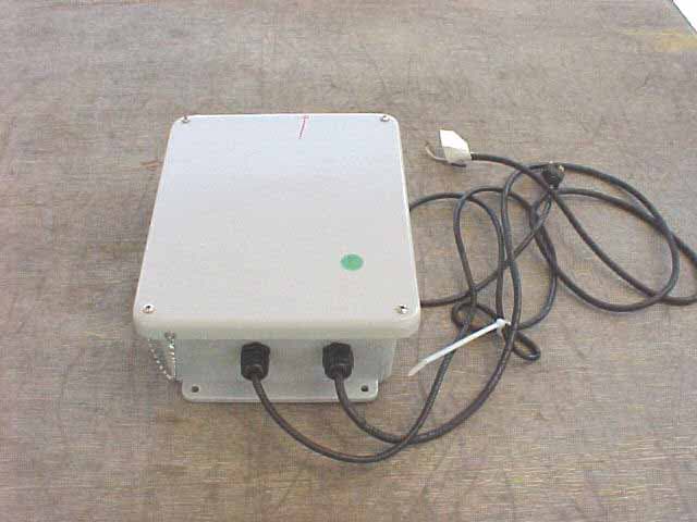
Click to zoom
Application Details
- Equipment Class
- DXT - Part 15 Low Power Transceiver, Rx Verified
- Date of Grant
- Sep 11, 2003
- Application Purpose
- Original Equipment
- Date of Application
- Sep 11, 2003
- Equipment Note
- Wireless Interface Unit
- Frequency Range
- 903.30000000 - 921.30000000
- Company
- Federal Signal Corporation
- Country
- United States
Documents & Files
Document Text
Text extracted from the exhibit documents filed with the FCC. Open a document above to read the original.
Users Manual
Atkinson Dynamics Wireless Interface Model ADWI Installation and Service Instructions Address all communications and shipments to: INSTALLATION AND SERVICE INSTRUCTIONS FOR ATKINSON DYNAMICS WIRELESS INTERFACE UNIT MODEL ADWI SAFETY MESSAGE TO INSTALLERS, USERS, AND MAINTENANCE PERSONNEL It is important to follow all instructions shipped with this product. This device is to be installed by a trained electrician who is thoroughly familiar with the National Electrical Code and will follow NEC Guidelines as well as local codes. Marine installations shall be in accordance with Title 46, CFR, Parts 110- 113. The selection of the mounting location for the device is to be accomplished under the direction of the facilities engineer and the safety engineer. In addition, listed below are some other important safety instructions and precautions you should follow: • This is not a listed safety device and is not intended to be used as such. • Read and understand all instructions before installing or operating this equipment. • Disconnect power before connecting or doing any maintenance on this unit. • After testing is complete, provide a copy of this instruction sheet to all operating personnel. • Establish a procedure to routinely check the intercom installation for integrity and proper operation. Any maintenance must be performed by a trained electrician in accordance with NEC guidelines and local codes. Failure to follow all safety precautions and instructions may result in property damage, serious injury, or death to you or others. A. GENERAL FEATURES. The Atkinson Dynamics wireless interface unit is a communications device designed for industrial applications that utilize a wired Atkinson Dynamics system and require communication with an Atkinson Dynamics wireless unit or system. The interface unit is housed in a NEMA Type 4X fiberglass enclosure with a hinged screw cover. The nominal operating voltage is 120VAC, 50/60 Hz. The AC power line is fused with a 1/2-amp, 250-volt type GMC fuse. Each unit is equipped with a 7-foot two-conductor audio cable for connection to any wired intercoms in the system. An RF transmitter and receiver, and a “whip” style antenna are contained inside each interface unit. The transmitter and receiver operate in the same frequency band, 902-928MHz, as the Atkinson Dynamics wireless intercom. A four-position switch, located on the printed circuit board inside the unit, allows the user to select the same channel of operation as the wireless intercoms. The wireless interface unit must be set to the same frequency channel as the wireless intercoms to communicate with each other. Refer to section E for details on setting the channel. Each unit is equipped with a squelch adjustment potentiometer, located inside the unit. The squelch adjustment allows the user to set the signal strength threshold level for the RF receiver in the interface unit. Refer to section F for more information on adjusting the squelch potentiometer. Model Specifications Supply Voltage 120VAC, 50/60 Hz Audio Power Output (Max.) Power Consumption (Max.) Operating Current (Nominal) 50 mA Operating Temperature Shipping Weight Dimensions (H x W x D) 11.62 x 9.41 x 4.25 Ratings UL, FCC (Part 15), NEMA-Type 4X Table 1 B. UNPACKING. After unpacking the Atkinson Dynamics wireless interface unit, examine it for damage that may have occurred in transit. If the equipment has been damaged, do not attempt to install or operate it, and file a claim immediately with the carrier stating the extent of the damage. Carefully check all envelopes, shipping labels and tags before removing or destroying them. C. MOUNTING. CAUTION The selection of the mounting location for the device is to be accomplished under the direction of the facilities and the safety engineer. NOTE The interface unit is intended to be mounted on any relatively flat and rigid surface by the four mounting ears on the exterior of the housing. The four mounting ears are 0.31" diameter holes. Refer to Figure 3 for the proper mounting configuration. Hardware for mounting the interface unit to the surface shall be provided by the installer. NOTE The unit should be mounted right side up so that the antenna (located inside the unit) is facing upward. Failure to do so may void FCC compliance. WARNING For shipboard applications, installations shall be in accordance with the United States Coast Guard, Title 46 CRF, Parts 110-113. D. ELECTRICAL CONNECTIONS. Plug the interface unit into a nearby power source. Each unit is equipped with a power cord that has a NEMA 5-15P molded plug. Connect the audio lines from the interface unit in parallel with the audio inputs from any wired intercoms in the system. Audio wires should be sized properly by your licensed installation electrician for your specified application. See figure 1 for a typical installation. E. CHANNEL SELECTION. Each unit is factory set to channel 3 (909.37 MHz). To select another channel, it is necessary to reconfigure the 4-position switch located on the printed circuit board inside the unit. To select another channel, perform the following steps: 1. Disconnect power from the unit. 2. Open the front cover by removing the four screws and lock washers. 3. Locate the 4-position switch on the circuit board. Refer to Figure 2. Use a nylon probe tool to change the position of the switch. Refer to table 3 for switch settings and their corresponding channel frequency. The setting of position 4 on the switch does not matter because it is not electrically connected. Positions 1 through 3 determine the channel frequency. 4. Close the front cover on the enclosure and reinstall the hardware removed in step 2. The interface unit and all other wireless intercoms in the system need to be set to the same channel to communicate with each other. Channel Frequency (MHz) SW1-3 SW1-2 SW1-1 0 903.37 ON ON ON 1 906.37 ON ON OFF 2 907.87 ON OFF ON 3 909.37 ON OFF OFF 4 912.37 OFF ON ON 5 915.37 OFF ON OFF 6 919.87 OFF OFF ON 7 …
Text truncated - open the document above for the full version.
Attestation Statements
FEDERAL SIGNAL CORPORATION Electrical Products August 28, 2003 Federal Communications Commission 7435 Oakland Mills RoadColumbia, MD 21046 Gentlemen: This is a letter of authorization to accept Compatible Electronics, Inc. as an agent for Federa! Signal Corporation (2645 Federal Signal Drive, University Park, IL 60466), for a period of one year, to sign applications before the Commission on our behalf, to make representations to you on our behalf, and to receive and exchange data between our company and the Commission in connection with certification of the following Federal Signal product: Wireless Interface Unit under FCC Docket Number 20780 and General Docket Number 80-284 pursuant to Part 15 of FCC Rules and Regulations. Please also accept this letter as an attestation that neither Federal Signal Corporation nor any of itsofficers, directors, or persons holding 5% or more of the outstanding stock or shares, voting or non-voting, have been denied federal benefits under section 5301 of the Anti-Drug-Abuse act of 1988,21 U.S.C. 853(a). In addition, Federal Signal Corporation will notify the Federal Communications Commission if, at any time, the situation changes causing Federal Signal Corporation to be denied federal benefits. If you have any further questions or need additional information, please feel free to give me a call at 708-534-3400. Sincerely,(:~~u cr( ~ J .--' Stephen Niemczak '(7'"-'- Director of Engineering Federal Signal Corporation 2645 Federal Signal Drive. University Park, Illinois 60466-3195. Phone: (708) 534-3400. www.federalsignal-indust.com
Attestation Statements
1 Scott McCutchan From: Scott McCutchan [[email protected]] Sent: Thursday, September 11, 2003 11:07 AM To: Kyle Fujimoto Subject: FCC ID: HVVADWI Scott McCutchan.vcf Mr. Fujimoto, In order for processing of this application (FCC ID: HVVADWI) to continue, the following issue(s) will have to be addressed: 1) Please indicate compliance with the voltage variation requirements of FCC Part 15, section 15.31(e). 2) Please indicate the type of modulation used by the transmitter. The item(s) indicated above must be submitted before processing can continue on the above referenced application. Failure to provide the requested information within 60 days of the original e-mail date may result in application dismissal and forfeiture of the filing fee. Also, please note that partial responses increase processing time and should not be submitted. Please upload your response to our electronic filing website using a correspondance number of "HVVADWI-1". If you have any questions, feel free to contact me. Best regards, Scott McCutchan Operations Manager Compatible Electronics TCB (714) 579-1489 fax (714) 579-1850 http://www.celectronics.com We also offer EMC Design Seminars! Click on the link below for details. http://www.celectronics.com/pdf/EMCsem1002.pdf Correspondence by Project Project Number: -811168353 Correspondence Number Memo HVVADWI-1 1) Please indicate compliance with the voltage variation requirements of FCC Part 15, section 15.31(e). Resposne: Sorry, forgot to upload the exhibit showing it complies with this section. This will be uploaded under exhibits. 2) Please indicate the type of modulation used by the transmitter. Response: The modulation is FSK (Frequency Shift Keying). Correspondence Number Memo HVVADWI-1test
Operational Description
EUT Operation The Atkinson Dynamics wireless interface unit is a communications device designed for industrial applications that utilize a "wired" Atkinson Dynamics system and require communication with an Atkinson Dynamics "wireless" unit or system. Each unit is equipped with a power cord that is terminated with a molded plug for 120VAC, SO/60Hz operation. A two-conductor audio cable attached to the unit enables connection to any wired intercom(s)in the system. An RF transmitter and receiver, manufactured by Linx Technologies, are located on a printed circuit board inside the unit. The RF parts operate in the 902-928 MHz band. A switch on the circuit board allows the user to select from eight channels (refer to Table 1below). A "whip" style ~-wavelength antenna is attached to an aluminum bracket that is mounted on the circuit board. An RG-174 coax cable, attached to theantenna, connects directly to the circuit board through a 50-ohm connector. In standby, the interface unit is in "receive" mode. The RF receiver is powered up and the antenna is connected to the receiver through an antenna switch. The interface unit may receive audio from a wired intercom at the interface connector Jl, or from a wireless intercom within range at the receiver "ANLG-QUT" pin. When the interface unit receives audio from a wireless intercom, the signal passes through a low pass filter and noise reduction stage to a preamplifier circuit. This signal then passes through a relay to connector Jl where it is broadcast on any wired intercoms that have audio lines connected to the interface unit. When an audio signal is present at interface connector Jl, it is routed through two different paths on the circuit board. One path is through an audio sense circuit. When audio is detected by this circuit, the transmitter turns on and the receiver turns off. The antenna is switched from the receiver to the transmitter. The second path for the audio at Jl is to relay K2. Once K2 energizes, the audio passes through to an attenuation circuit and then to the transmitter ANLG-IN pin. The audio signal will then be broadcast on any wireless intercoms that are within range of the interface unit's transmitter. All units are equipped with a squelch adjustment control potentiometer that is located on the circuit board. The squelch adjustment allows the end user to adjust the signal strength threshold level of the RF receiver in the interface unit. The incoming signal level must be higher than the signal strength threshold level for the receiver to acknowledge it; otherwise, the audio will be squelched. CS2 0 0 0 0 1 1 1 1 CSl 0 0 1 1 0 0 1 1 cso 0 1 0 1 0 1 0 1 Channel 0 1 2 3 4 5 6 7 Frequency (MHz) 903.37 906.37 907.87 909.37 912.37 915.37 919.87 921.37 Channel-Selection Table Table 1:
Test Report
Report Number: B30821D1 FCC Part 15 Subpart B and FCC Section 15.249 Test Report Wireless Interface Unit Model: ADWI 114 OLINDA DRIVE, BREA, CALIFORNIA 92823 PHONE: (714) 579-0500 FAX: (714) 579-1850 Page 1 of 16 FCC PART 15, SUBPART B and C TEST REPORT for WIRELESS INTERFACE UNIT MODEL: ADWI Prepared for FEDERAL SIGNAL CORPORATION 2645 FEDERAL SIGNAL DRIVE UNIVERSITY PARK, ILLINOIS 60466-3195 Prepared by:_____________________ KYLE FUJIMOTO Approved by:____________________ MICHAEL CHRISTENSEN COMPATIBLE ELECTRONICS INC. 114 OLINDA DRIVE BREA, CALIFORNIA 92823 (714) 579-0500 DATE: SEPTEMBER 4, 2003 REPORT APPENDICES TOTAL BODY A B C D E PAGES 16 2 2 2 13 16 51 This report shall not be reproduced except in full, without the written approval of Compatible Electronics. Report Number: B30821D1 FCC Part 15 Subpart B and FCC Section 15.249 Test Report Wireless Interface Unit Model: ADWI 114 OLINDA DRIVE, BREA, CALIFORNIA 92823 PHONE: (714) 579-0500 FAX: (714) 579-1850 Page 2 of 16 TABLE OF CONTENTS Section / Title PAGE GENERAL REPORT SUMMARY 4 SUMMARY OF TEST RESULTS 4 1. PURPOSE 5 2. ADMINISTRATIVE DATA 6 2.1 Location of Testing 6 2.2 Traceability Statement 6 2.3 Cognizant Personnel 6 2.4 Date Test Sample was Received 6 2.5 Disposition of the Test Sample 6 2.6 Abbreviations and Acronyms 6 3. APPLICABLE DOCUMENTS 7 4. DESCRIPTION OF TEST CONFIGURATION 8 4.1 Description of Test Configuration - EMI 8 4.1.1 Cable Construction and Termination 9 5. LISTS OF EUT, ACCESSORIES AND TEST EQUIPMENT 10 5.1 EUT and Accessory List 10 5.2 EMI Test Equipment 11 6. TEST SITE DESCRIPTION 12 6.1 Test Facility Description 12 6.2 EUT Mounting, Bonding and Grounding 12 7. Test Procedures 13 7.1 Conducted Emissions Test 13 7.2 Radiated Emissions (Spurious and Harmonics) Test 14 8. CONCLUSIONS 16 Report Number: B30821D1 FCC Part 15 Subpart B and FCC Section 15.249 Test Report Wireless Interface Unit Model: ADWI 114 OLINDA DRIVE, BREA, CALIFORNIA 92823 PHONE: (714) 579-0500 FAX: (714) 579-1850 Page 3 of 16 LIST OF APPENDICES APPENDIX TITLE A Laboratory Recognitions B Modifications to the EUT C Additional Models Covered Under This Report D Diagrams, Charts, and Photos • Test Setup Diagrams • Radiated and Conducted Emissions Photos • Antenna and Effective Gain Factors E Data Sheets LIST OF FIGURES FIGURE TITLE 1 Conducted Emissions Test Setup 2 Plot Map And Layout of Test Site Report Number: B30821D1 FCC Part 15 Subpart B and FCC Section 15.249 Test Report Wireless Interface Unit Model: ADWI 114 OLINDA DRIVE, BREA, CALIFORNIA 92823 PHONE: (714) 579-0500 FAX: (714) 579-1850 Page 4 of 16 GENERAL REPORT SUMMARY This electromagnetic emission test report is generated by Compatible Electronics Inc., which is an independent testing and consulting firm. The test report is based on testing performed by Compatible Electronics personnel according to the measurement procedures described in the test specifications given below and in the "Test Procedures" section of this report. The measurement data and conclusions appearing herein relate only to the sample tested and this report may not be reproduced without the written permission of Compatible Electronics, unless done so in full. This report must not be used to claim product endorsement by NVLAP, NIST, or any other agency of the U.S. Government. Device Tested: Wireless Interface Unit Model: ADWI S/N: N/A Product Description: See Expository Statement. Modifications: The EUT was not modified during the testing. Manufacturer: Federal Signal Corporation 2645 Federal Signal Drive University Park, Illinois 60466-3195 Test Date: August 21, 2003 Test Specifications : EMI requirements CFR Title 47, Part 15 Subpart B; and Subpart C, Sections 15.205, 15.207, 15.209, and 15.249 Test Procedure: ANSI C63.4: 2001 Test Deviations: The test procedure was not deviated from during the testing. SUMMARY OF TEST RESULTS TEST DESCRIPTION RESULTS 1 Conducted RF Emissions, 150 kHz - 30 MHz Complies with the Class B limits of CFR Title 47, Part 15, Subpart B; and Subpart C, section 15.207. 2 Radiated RF Emissions, 10 kHz - 9300 MHz Complies with the Class B limits of CFR Title 47, Part 15, Subpart B; and Subpart C, sections 15.205, 15.209, and 15.249. Report Number: B30821D1 FCC Part 15 Subpart B and FCC Section 15.249 Test Report Wireless Interface Unit Model: ADWI 114 OLINDA DRIVE, BREA, CALIFORNIA 92823 PHONE: (714) 579-0500 FAX: (714) 579-1850 Page 5 of 16 1. PURPOSE This document is a qualification test report based on the Electromagnetic Interference (EMI) tests performed on the Wireless Interface Unit Model: ADWI. The EMI measurements were performed according to the measurement procedure described in ANSI C63.4: 2001. The tests were performed in order to determine whether the electromagnetic emissions from the equipment under test, referred to as EUT hereafter, are within the Class B specification limits defined by CFR Title 47, Part 15, Subpart B; and Subpart C, sections 15.205, 15.207, 15.209, and 15.249. Report Number: B30821D1 FCC Part 15 Subpart B and FCC Section 15.249 Test Report Wireless Interface Unit Model: ADWI 114 OLINDA DRIVE, BREA, CALIFORNIA 92823 PHONE: (714) 579-0500 FAX: (714) 579-1850 Page 6 of 16 2. ADMINISTRATIVE DATA 2.1 Location of Testing The EMI tests described herein were performed at the test facility of Compatible Electronics, 114 Olinda Drive, Brea, California 92823. 2.2 Traceability Statement The calibration certificates of all test equipment used during the test are on file at the location of the test. The calibration is traceable to the National Institute of Standards and Technology (NIST) . 2.3 Cognizant Personnel Federal Signal Corporation Pat Morasan Engineer Stephen Niemczak Director of Engineering Compatible Electronics, Inc. Kyle Fujimoto Test Engineer Michael Christensen Test Engineer 2.4 Date Test Sample was Received The test sample was received on August 20, 2003. 2.5 Disposition of the Test Sample The sample was returned to Federal Signal Corporation on Septem…
Text truncated - open the document above for the full version.
Test Report
HOW THE EUT MEETS THE REQUIREMENTS OF 15.31 (e) The fundamental was maximized on the test site using a normal test setup with the Wireless Interface Unit Model: ADWI (EUT) power cord connected directly to the AC public mains (115 VAC). Next, the EUT’s power cord was then connected to the Staco Energy Products Variable Auto Transformer Model: 3PN1010. The Variable Auto Transformer allows the Vac input to be varied. The EUT’s power cord was then connected to the Staco Energy Products Variable Auto Transformer Model: 3PN1010. The AC input was then dropped to 85% (97.75 Vac) and raised to 115% (132.25 Vac). The actual AC input was measured using a calibrated Fluke Multimeter Model: 87, Serial Number: 51350019, Calibration Due Date: July 11, 2004. The fundamental was then verified again to see that the amplitude did not change. Test Result: The Wireless Interface Unit Model: ADWI (EUT) does NOT change amplitude at the fundamental when the AC input voltage is varied between 85% and 115% of the input nominal rated supply voltage.
Contact Information
Applicant
Scott Cassidy(Engineering Manager)
708 534-4860Fax: 708 534-4855
Technical Contact
Compatible ElectronicsKyle Fujimoto
[email protected]714-579-0500
114 Olinda Drive · Brea, California · United States
Test Firm
Compatible ElectronicsScott McCutchan
714-579-0500Fax: 714-579-1850
Technical Specifications
| # | Rule Parts | Frequency Range | Power Output |
|---|---|---|---|
| 1 | 15C | 903.3 MHz - 921.3 MHz | - |
Other Applications from Federal Signal Corporation
HVVVB
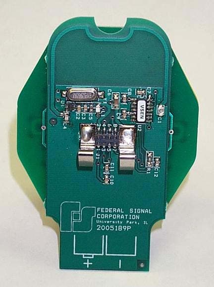
Jun 20, 2006Periodic Transmitter for VisiBeam search light
Equipment Class
DSC - Part 15 Security/Remote Control Transmitter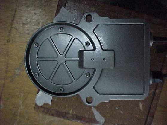
HVVAD27W1
Apr 13, 2004Wireless Intercom
Equipment Class
DXT - Part 15 Low Power Transceiver, Rx Verified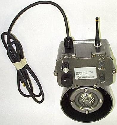
HVVAD27W
May 22, 2002Wireless Intercom
Equipment Class
DXT - Part 15 Low Power Transceiver, Rx VerifiedHVVI
Jun 24, 1998Emergency Alert Receiver
Equipment Class
CXX - Communications Rcvr for use w/ licensed Tx and CBsHVVEARL
Apr 17, 1997CXX - Communications Rcvr for use w/ licensed Tx and CBs
Equipment Class
CXX - Communications Rcvr for use w/ licensed Tx and CBs