HVVVBPeriodic Transmitter for VisiBeam search light
Federal Signal Corporation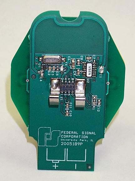
Click to zoom
Application Details
- Equipment Class
- DSC - Part 15 Security/Remote Control Transmitter
- Date of Grant
- Jun 20, 2006
- Application Purpose
- Original Equipment
- Date of Application
- Jun 20, 2006
- Equipment Note
- Periodic Transmitter for VisiBeam search light
- Frequency Range
- 433.80000000 - 434.00000000
- Company
- Federal Signal Corporation
- Country
- United States
Documents & Files
Document Text
Text extracted from the exhibit documents filed with the FCC. Open a document above to read the original.
External Photos
Authorized Agent: Radiometrics Midwest Corporation (815) 293-0772 – [email protected] External EUT Photographs FCC ID: HVVVB Front of EUT Back of EUT
ID Label/Location Info
Authorized Agent: Radiometrics Midwest Corporation (815) 293-0772 – [email protected] EUT Labeling FCC ID: HVVVB The label material is 2 mil silver matte polyester with a 1 mil clear polyester over laminate. The label uses an S333 permanent adhesive Authorized Agent: Radiometrics Midwest Corporation (815) 293-0772 – [email protected] Location of Label:
Internal Photos
Authorized Agent: Radiometrics Midwest Corporation (815) 293-0772 – [email protected] Internal EUT Photographs FCC ID: HVVVB Photograph of battery compartment Photograph of Keypad Authorized Agent: Radiometrics Midwest Corporation (815) 293-0772 – [email protected] Photograph of Keypad Board – Foil Side Authorized Agent: Radiometrics Midwest Corporation (815) 293-0772 – [email protected] Photograph EUT Partially Assembled Authorized Agent: Radiometrics Midwest Corporation (815) 293-0772 – [email protected] Photograph of RF Board – Component & Foil Side
Operational Description
EUT Description FCC ID: HVVVB Radio Frequency, Modulation, and Antenna 433.92 MHz nominal On/Off Keying Modulation Internal PCB Trace Loop Antenna in the Transmitter Transmission Message Signature A transmission message is composed of: 1) Preamble: 16 cycles of square wave, T=0.76ms 50% duty 2) Header: off time T = 3.76 ms 3) Encrypted portion: 32 bits, T= 1.14 ms each 33% duty for logic ‘1’, 66% duty for logic ‘0’ 4) Open portion: 35 bits, T= 1.14 ms each 33% duty for logic ‘1’, 66% duty for logic ‘0’ 5) Blank Time after a transmission: T= 142.6 ms A transmission message is generated at each press of a function button (lamp on/off and motion buttons). When a button is held longer than the Transmission Time plus the Blank Time (235 ms), the transmission is repeated. When the previously pressed function button is released, the transmission will cease not later than after the previously begun transmission completes, which is, in less than 100 ms. A button held constantly will be ignored after approximately 20 seconds to conserve battery power. RF Power 2 mW pulsed The "Wireless VisiBeam" is a wireless version of the Federal VisiBeam search light. Model 620200 is a permanent/pipe mount 12Vdc; Model 620201 is a magnet mount 12Vdc; Model 620202 is a permanent/pipe mount 24Vdc. The difference between 12 and 24-volt models is only in the lamp and motor rating, while the electronic assemblies are identical. The light uses the combination of a highly polished parabolic reflector and a halogen bulb, 100 W maximum, to produce a clear, even light beam superior to both “spot” and “flood” sealed beams. It can be rotated horizontally 360 degrees continuously, left or right. It can elevate from 35 degrees down to 105 degrees up. The light assembly uses electric motors and gears driven by an electronic board. The electronic board contains a power transistor serving as the light switch, horizontal and vertical full-bridge motor drives, a receiver, and a decoder of remote control signals. The remote control, powered by two AA batteries, transmits encoded control signals. Each transmitter has a unique serial number and transmission signature. A given transmitter can be assigned to its unique receiver through a Learn Process. One transmitter can work with more than one receiver if the Learn Process was repeated with the same transmitter on a different receiver. Up to four transmitters can be learned on a given receiver; the fifth one will override one of the former ones at random. An Erase All Transmitters process is also available. The search light assembly has three connectors: a power connector, a horizontal motor connector and a vertical motor connector. The electronic board is protected against reverse polarity, but the lamp will be on constantly during the reversed power connection. The circuit board also contains circles for connecting brushes that provide power to the halogen lamp. The search light assembly should be externally fused at 10 amperes for 12 volts or 5 amperes for 24 volts. The transmitter has a reverse polarity protection built into the battery connections, which will remain open in case of improper polarity of inserted batteries. The electronic transmitter will be damaged if the power of reverse polarity or improper voltage is connected internally. The transmitter is a compact unit that ergonomically fits in the palm of a hand. It has five buttons, large enough to be operated while wearing a glove: Red Lamp ON/OFF in the center, and four Yellow buttons for the Up, Down, Left, and Right movement. It also has a red LED that blinks when the buttons are pressed. To conserve battery power, the LED is operated at lower light intensity. Also, to limit accidental button activation, any button pressed for longer than about twenty seconds will be deactivated, until released and pressed again.
RF Exposure Info
Authorized Agent: Radiometrics Midwest Corporation (815) 293-0772 – [email protected] RF exposure The output power of the EUT is 2 mW and the gain of the antenna is 2dBi The following information provides the minimum separation distance for the EUT, as calculated from FCC OET 65 Appendix B, Table 1B “Guidelines for General Population/Uncontrolled Exposure” This calculation is based on the highest EIRP possible from the EUT considering maximum power and antenna gain. The formulas were used: GP limit is = 0.29 mW/cm^2 for 434 MHz (from F/1500) Pwatts*Ggain or ERP = 10^(PdBm-30+GdBi)/10) =0.003 Watts 0.003 Watts = 5 dBm S= E^2/3770 mW/cm^2 E or V/m = (ERP*30)^0.5/d, (d in meters) d = ((ERP*30)/3770*S))^0.5 SMaximum AntennaMSD Freq.GP limitRF power GainERPEd MHzmW/cm^2 dBmdBiwattsV/mmeters 434 0.289333320.00333.00.009 GP is the limit for general Population/Uncontrolled Exposure MSD is the minimum Seperation Distance NOTE: For mobile or fixed location transmitters, minimum separation distance is 20 cm, even if calculations indicate MPE distance is less
Test Report
Radiometrics Midwest Corporation (815) 293-0772 – www.radiomet.com Page 1 of 11 Electromagnetic Compatibility Test Report Tests Performed on a Federal Signal Corporation Transmitter, Model VisiBeam Radiometrics Document RP-5698A Product Detail: FCC ID: HVVVB Equipment type: 433.9 MHz Momentarily operated Transmitter Test Standards: US CFR Title 47, Chapter I, FCC Part 15 Subpart C FCC Part 15 CFR Title 47: 2006 This report concerns: Original Grant for Certification FCC Part 15.231 Tests Performed For: Test Facility: Federal Signal Corporation 2645 Federal Signal Dr. University Park, IL 60466 Phone: (708) 534-3400 Radiometrics Midwest Corporation 12 East Devonwood Romeoville, IL 60446 Phone: (815) 293-0772 e-mail: [email protected] Test Date(s): (Month-Day-Year) December 19, 2005 and June 7, 2006 Document RP-5698A Revisions: Rev. Issue Date Affected Pages Revised By 0 June 5, 2006 1 June 16, 2006 8, 11 Joseph Strzelecki RADIOMETRICS MIDWEST CORPORATION - EMC Test Report Testing of the Federal Signal Corporation, Model VisiBeam , Transmitter RP-5698A Rev. 1 Page 2 of 11 Table of Contents 1 ADMINISTRATIVE DATA ................................................................................................................... 3 2 TEST SUMMARY AND RESULTS .....................................................................................................3 2.1 RF Exposure Compliance Requirements ..................................................................................... 3 3 EQUIPMENT UNDER TEST (EUT) DETAILS .................................................................................... 3 3.1 EUT Description ........................................................................................................................... 3 3.1.1 FCC Section 15.203 Antenna Requirements......................................................................... 4 3.2 Related Submittals ....................................................................................................................... 4 4 TESTED SYSTEM DETAILS .............................................................................................................. 4 4.1 Tested System Configuration ....................................................................................................... 4 4.2 Special Accessories ..................................................................................................................... 4 4.3 Equipment Modifications .............................................................................................................. 4 5 TEST SPECIFICATIONS AND RELATED DOCUMENTS.................................................................. 4 6 RADIOMETRICS’ TEST FACILITIES .................................................................................................5 7 DEVIATIONS AND EXCLUSIONS FROM THE TEST SPECIFICATIONS......................................... 5 8 CERTIFICATION ................................................................................................................................ 6 9 TEST EQUIPMENT TABLE ................................................................................................................ 6 10 TEST SECTIONS ............................................................................................................................. 6 10.1 Radiated RF Emissions .............................................................................................................. 6 10.1.1 Field Strength Calculation.................................................................................................... 7 10.1.2 Radiated Emissions Test Results ........................................................................................ 7 10.2 Occupied Bandwidth Data .......................................................................................................... 9 Notice: This report must not be reproduced (except in full) without the written approval of Radiometrics Midwest Corporation. RADIOMETRICS MIDWEST CORPORATION - EMC Test Report Testing of the Federal Signal Corporation, Model VisiBeam , Transmitter RP-5698A Rev. 1 Page 3 of 11 1 ADMINISTRATIVE DATA Equipment Under Test: A Federal Signal Corporation, Transmitter Model: Visibeam Serial Number: N/A This will be referred to as the EUT in this Report Date EUT Received at Radiometrics: (Month-Day-Year) Test Date(s): (Month-Day-Year) October 27, 2005 December 19, 2005 thru June 7, 2006 Test Report Written By: Test Witnessed By: Joseph Strzelecki Senior EMC Engineer Jacek Jozwik Federal Signal Corporation Radiometrics’ Personnel Responsible for Test: Test Report Approved By Joseph Strzelecki Senior EMC Engineer NARTE EMC-000877-NE Chris W. Carlson Director of Engineering NARTE EMC-000921-NE 2 TEST SUMMARY AND RESULTS The EUT (Equipment Under Test) is a Transmitter, Model VisiBeam, manufactured by Federal Signal Corporation. The detailed test results are presented in a separate section. The following is a summary of the test results. Emissions Tests Results Environmental Phenomena Frequency Range Basic Standard Test Result RF Radiated Emissions 30-4400 MHz FCC Part 15 Pass Occupied Bandwidth Test Fundamental Freq. FCC Part 15 Pass 2.1 RF Exposure Compliance Requirements The power output is 2 mW, The EUT meets the FCC requirement for RF exposure. There are no power level adjustments and the antenna is permanently attached. The detailed calculations for RF Exposure are presented in a separate document. 3 EQUIPMENT UNDER TEST (EUT) DETAILS 3.1 EUT Description The EUT is a Transmitter, Model VisiBeam , manufactured by Federal Signal Corporation. The EUT was in good working condition during the tests, with no known defects. RADIOMETRICS MIDWEST CORPORATION - EMC Test Report Testing of the Federal Signal Corporation, Model VisiBeam , Transmitter RP-5698A Rev. 1 Page 4 of 11 3.1.1 FCC Section 15.203 Antenna Requirements The antenna is an Internal PCB Trace Loop Ante…
Text truncated - open the document above for the full version.
Test Setup Photos
Authorized Agent: Radiometrics Midwest Corporation (815) 293-0772 – [email protected] Test Setup Photographs Photograph of Radiated Emissions Test Setup
Contact Information
Applicant
Scott Cassidy(Engineering Manager)
708 534-4860Fax: 708 534-4855
Test Firm
Radiometrics Midwest Corp.Joseph Strzelecki
Technical Specifications
| # | Rule Parts | Frequency Range | Power Output |
|---|---|---|---|
| 1 | 15.231(e) | 433.8 MHz - 434 MHz | - |
Other Applications from Federal Signal Corporation
HVVAD27W1
Apr 13, 2004Wireless Intercom
Equipment Class
DXT - Part 15 Low Power Transceiver, Rx Verified
HVVADWI
Sep 11, 2003Wireless Interface Unit
Equipment Class
DXT - Part 15 Low Power Transceiver, Rx Verified
HVVAD27W
May 22, 2002Wireless Intercom
Equipment Class
DXT - Part 15 Low Power Transceiver, Rx VerifiedHVVI
Jun 24, 1998Emergency Alert Receiver
Equipment Class
CXX - Communications Rcvr for use w/ licensed Tx and CBsHVVEARL
Apr 17, 1997CXX - Communications Rcvr for use w/ licensed Tx and CBs
Equipment Class
CXX - Communications Rcvr for use w/ licensed Tx and CBs