I28-P100IP100i
Zebra Technologies Corporation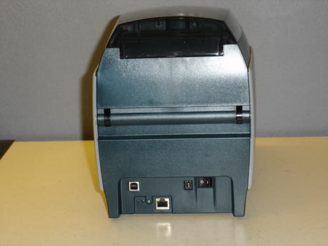
Click to zoom
Application Details
- Equipment Class
- DXX - Part 15 Low Power Communication Device Transmitter
- Date of Grant
- Oct 01, 2007
- Application Purpose
- Original Equipment
- Date of Application
- Oct 01, 2007
- Equipment Note
- P100i
- Frequency Range
- 13.56000000 - 13.56000000
- Country
- United States
Documents & Files
Document Text
Text extracted from the exhibit documents filed with the FCC. Open a document above to read the original.
Users Manual
Zebra ® P100i ™ Card Printer User’s Manual 980590-001 Rev. A Draft 1 Review Copy Aug 10, 2007 2P100i User’s Manual980590-001 Rev. A Draft 1 980590-001 Rev. A Draft 1P100i User’s Manualiii Foreword This manual contains installation and operation information for the Zebra P100i card printers manufactured by Zebra Technologies Corporation. Copyright Notice © 2004 ZIH Corp. This document contains information proprietary to Zebra Technologies Corporation. This document and the information contained within is Copyrighted by Zebra Technologies Corporation and may not be duplicated in full or in part by any person without written approval from Zebra Technologies Corporation. While every effort has been made to keep the information contained within current and accurate as of the date of publication, no guarantee is given that the document is error-free or that it is accurate with regard to any specification. Zebra Technologies Corporation reserves the right to make changes, for the purpose of product improvement, at any time. Trademarks P100i is a trademark and Zebra is a registered trademark of Zebra Technologies Corporation. Windows is a registered trademark of Microsoft Corp. All other trademarks or registered trademarks are marks of their respective holders. ivP100i User’s Manual980590-001 Rev. A Draft 1 Foreword Product Disposal Product Disposal Return Materials Authorization Before returning any equipment to Zebra Technologies Corporation for in-warranty or out-of- warranty repair, contact Repair Administration for a Return Materials Authorization (RMA) number. Repack the equipment in the original packing material and mark the RMA number clearly on the outside. Ship the equipment, freight prepaid, to the address listed below: Declarations of Conformity FCC Regulations Model P100i has been tested and found to comply with the limits for a Class A digital device, pursuant to Part 15 of the FCC Rules. These limits are designed to provide reasonable protection against harmful interference when the equipment is operated in a commercial environment. This equipment generates, uses, and can radiate radio frequency energy and, if not installed and operated in accordance with the P100i User’s Manual, may cause harmful interference to radio communications. Operation of this equipment in a residential area is likely to cause harmful interference in which case the user will be required to correct the interference at his own expense. Pursuant to Part 15.21 of the FCC Rules, any changes or modifications to this equipment not expressly approved by Zebra may cause harmful interference and void the FCC authorization to operate this equipment. Product Disposal Information • Do not dispose of this product in unsorted municipal waste. This product is recyclable, and should be recycled according to your local standards. For more information, please see our web site at: http://www.zebra.com/environment For USA, Latin America, and Asia / Pacific: Zebra Technologies Corporation Zebra Card Printer Solutions 1001 Flynn Road Camarillo, CA. 93012-8706.USA Phone: +1 (805) 578-5001 FAX: +1 (805) 579-1808 For Europe and Middle East: Zebra Technologies Corporation Zebra Card Printer Solutions Pittman Way, Fulwood Preston, PR2 9ZD Lancashire, U.K. Phone: +44 - 1 - 772 - 797555 FAX: +44 - 1 - 772 - 693000 Foreword Declarations of Conformity 980590-001 Rev. A Draft 1P100i User’s Manualv Industry Canada Notice This device complies with Industry Canada ICES-003 class A requirements. Cet équipement est conforme à l’ICES-003 classe A de la Norm Industrielle Canadienne. For a formal certificate, please contact the Compliance Office at Zebra’s Camarillo facility. EUROPE: Norway Only: This product is also designed for IT power system with phase to phase voltage 230V. Earth grounding is via the polarized, 3-wire power cord. FI: “Laite on liitettävä suojamaadoitus koskettimilla varustettuun pistorasiaan” SE: “Apparaten skall anslutas till jordat uttag” NO: “Apparatet må tilkoples jordet stikkontakt” 89/336/EEC modified by 92/31/EEC and 93/68/EEC EMC Directive EN 55022 (1998) RF Emissions control EMC Directive EN 301489-3 V1.4.1 RF Emissions and Immunity for radio equipment EMC Directive EN55024 (2001) Immunity to Electro-Magnetic Disturbances 73/23/EEC modified by 93/ 68/EEC Low voltage Directive EN 60950-1 (2001) Product safety 1999/5/CE R&TTE Directive EN300330-2 V1.1.1 Radio Frequency Interferences viP100i User’s Manual980590-001 Rev. A Draft 1 Foreword Icons Icons Throughout this manual, different icons highlight important information, as follows: Note • Indicates information that emphasizes or supplements important points of the main text. Advises you of information that is essential to complete a task, or points out the importance of specific information in the text. Electric Shock Caution • Warns you of a potential electric shock situation. Electrostatic Discharge Caution • Warns you of a situation where electrostatic discharge could cause damage to electronic components. Caution • Advises you that failure to take or avoid a specific action could result in physical harm to you, or could result in physical damage to the hardware. Foreword P100i Printer Model 980590-001 Rev. A Draft 1P100i User’s Manualvii P100i Printer Model The Zebra Product Number tells a story: Here is a quick review of the Zebra Card Printer Series numbering and lettering system to help you. Model numbers include identifiers that specify options using the following lettering conventions: Part NumberDescription P 1 0 0 i - _ _ _ _ _ - _ _ _ Base Printer P100i Single Card Feed, Single Sided Color Card Printer _ _ _ _ _ - 0 _ _ _ _ - _ _ _ _ _ _ _ _ - B _ _ _ _ - _ _ _ _ _ _ _ _ - D _ _ _ _ - _ _ _ _ _ _ _ _ - H _ _ _ _ - _ _ _ Smart Card Options None Contact Encoder Contact Encoder & MIFARE contactless MIFARE contactless _ _ _ _ _ - _ 0 _ _ _ - _ _ _ _ _ _ _ _ - _ M _ _ _ - _ _ _ Magnetic Encoder None Yes (select defaults below) _ _ _ _ _ - _ _ 0 _ _ - _ _ _ _ …
Text truncated - open the document above for the full version.
Users Manual
980590-001 Rev. A Draft 1P100i User’s Manual37 5 Cleaning Cleaning System Yo u r P 1 0 0i Printer includes a simple cleaning system using Pre-Saturated Cleaning Cards provided. The regular use of these cards will clean and maintain important parts of your printer that cannot be reached: including Print Head, the Transport Rollers, and the Magnetic Encoder Station (optional feature). When to Clean After approximately 1000 color cards have been printed, the printer LCD will prompt CLEAN PRINTER, or when print quality has been degraded. How to Clean 1.Leave power on. 2.Press and hold the Multi-Function Control Button for 5 seconds. 3.When the cleaning cycle is initiated, the LCD message REMOVE RIBBON THEN CLOSE LID will display. N Caution • PROTECT YOUR FACTORY WARRANTY! The recommended maintenance procedures must be performed to maintain your factory warranty. Other than the recommended cleaning procedures described in this manual, allow only Zebra authorized technicians to service the P100i Printer. NEVER loosen, tighten, adjust, or bend, etc., a part or cable inside the printer. NEVER use a high-pressure air compressor to remove particles in the printer. 38P100i User’s Manual980590-001 Rev. A Draft 1 Cleaning Cleaning System 4.After the ribbon is removed and the lid is closed, the message EMPTY FEEDER THEN CLOSE COVER will display. 5.If the lid is opened and closed without removing the ribbon, the REMOVE RIBBON THEN CLOSE LID message will remain. 6.Once the cover is closed, the firmware will eject any card inside the printer. The message EJECTING CARD will display. 7.The LCD will then display FEED LONG CLEANING CARD IN EXIT. When the card sensor registers the presence of the cleaning card, the rollers should take the card into the printer. 8.When the cleaning process is done, the printer will eject the cleaning card. If the card sensor still senses the cleaning card, the message REMOVE LONG CLEANING CARD will display. 9.After the card is removed, the LCD will display READY. You may now reload the ribbon and continue printing. Printer Path Cleaning Card Multi-Function Control Button Multi-Function LCD Panel Cleaning Cleaning the Print Head 980590-001 Rev. A Draft 1P100i User’s Manual39 Cleaning the Print Head Use of the cleaning cards will normally do an adequate job of cleaning the printer. However, a separate Print head cleaning, using swabs, can remove more stubborn deposits when print anomalies persist. To avoid deposits, only use foam-tipped swabs. 1.Place the printer power switch in the OFF (0) position. 2.Open printer lid by pressing cover release button and open cover fully to reveal the print head mounted to inside of the cover. 3.Clean Print Head by moving alcohol-moistened swab tip side-to-side across Print Head elements. Only use moderate force. 4.Allow two to three minutes for the printhead to dry before placing the printer power switch in the ON ( | ) position. 5.To reorder swabs, reference the P110i Printer Media List. Caution • Never use a sharp object to scrape deposits from the print head. Permanent damage to the print head will result 40P100i User’s Manual980590-001 Rev. A Draft 1 980590-001 Rev. A Draft 1P100i User’s Manual41 6 Troubleshooting Troubleshooting Procedures The table below offers causes and solutions to symptoms related to improper operation. Check the table when experiencing any loss of operation or print quality. Problem / DescriptionCause / Solution The LCD Panel displays OUT OF RIBBON message. 1. Check ribbon. Replace if defective or entirely used. Ribbon will automatically synchronize and printing will restart with a new card. The LCD Panel displays PRINT HEAD OPEN message. 1. Check that Print Head Carriage is closed and latched. If not, close and latch it. 42P100i User’s Manual980590-001 Rev. A Draft 1 Troubleshooting Troubleshooting Procedures Print Quality Issues This section will help you resolve print quality problems The print quality is dependent on several factors. The two most important factors that will increase your print quality are cleanliness and card stock. To diagnose and fix print quality problems, follow the troubleshooting procedures below: The LCD Panel displays MECHANICAL ERROR message. 1. Check that you are using the correct card type (see Technical Specifications). 2. Check that ribbon is loaded correctly. The LCD Panel displays ENCODING ERROR message. 1. Check that you are using the correct magnetic card type (for low or high coercivity encoding). 2. Verify command syntax. 3. Contact Zebra technical support. The LCD Panel displays CLEAN PRINTER message. 1. Printer cleaning required (see Chapter 4). Troubleshooting Troubleshooting Procedures 980590-001 Rev. A Draft 1P100i User’s Manual43 Example • Small spots appear on the printed card with a non-printed area or a different color. Possible Cause: •Contamination on the card surface Solutions: •Check that cards are stored in a dust free environment •Use a different supply of cards Possible Cause: •Cleaning roller not installed •Dust inside the printer and/or dirty Cleaning Roller Solutions: •Perform a Cleaning of the printer (reference Chapter 5) •Check that the protective cover was removed from the ribbon cartridge cleaning roller (reference Chapter 3). •Replace the cleaning roller located at the front of the printer (reference Appendix B). Example • There are non-printing horizontal lines (white) on the card surfaces. Possible Cause: •Ribbon cartridge is not correctly positioned. Solutions: •Ensure that the ribbon is properly rolled onto the ribbon cores of the cartridge and that there are no wrinkles in the ribbon. •Replace ribbon cassette. Possible Cause: •Print Head is dirty. Solutions: •Clean the Print Head Possible Cause: •Print Head elements are damaged (e.g., scratched or burnt). Solutions: •Call Zebra Customer Service for Print Head replacement information. 44P100i User’s Manual980590-001 Rev. A Draft 1 Troubleshooting Troubleshooting Procedures Example • Printing shows …
Text truncated - open the document above for the full version.
Cover Letter(s)
August 9, 2007 Federal Communication Commission Authorization and Evaluation Division 7435 Oakland Mills Road Columbia, MD 21046 RE: FCC ID: 128-P1001 To whom it may concern, We, the undersigned, hereby authorize Northwest EMC, Inc., to act on our behalf, as our agent, in the following matters related to the FCC approval of our products: report submittal, related correspondence, the signing of all documents relating to these matters, and any other lawful activity necessary to obtain such certification. Any act carried out by Northwest EMC, Inc. within the scope of this authorization shall have the same affect as our own. Model Number: P100i P100i Card Printer with Mifare Contactless Encoder option, Gem+ Contact Encoder option, Magnetic Stripe Encoder option and Ethernet option This authorization shall expire 12 months from original date. Sincerely, George ~Anj a~fgolian Compliance Manager Zebra Technologies, CPS Division 805-578-1340 Zebra TBchnologies Corporation 1001 Flynn Road ~ Camarillo, CA 93012 8706 USA T+I 805 579 !800 F+I 805 579 1808 www.zebra corn
Cover Letter(s)
NORTHWEST EMC, INC. 22975 NW Evergreen Parkway, Suite 400 Hillsboro, OR 97124 August 27, 2007 Dear Application Examiner: On behalf of Zebra Technologies Corporation, Northwest EMC Inc is submitting this application for a limited modular approval of Zebra’s 13.56MHz Mifare radio, FCC ID: I28-P100I. The 13.56MHz radio is factory installed in the P100i card printer with Mifare Contactless Encoder. The P100i can be connected to the AC mains. The radio utilizes a single internal antenna. The antenna and radio are not user accessible. This configuration satisfies the requirements of 47 CFR 15.203. The technical reports and exhibits demonstrate compliance with FCC rules 47 CFR 15.225 as a RFID transmitter. Your efforts in reviewing this application are greatly appreciated. Best regards, Northwest EMC, Inc.
Cover Letter(s)
Northwest EMC TCB Compliance Opinion Rev. 9/15/03 ZEBR0020 Information about the Applicant Grantee (Company Name) Zebra Technologies Corporation FCC Contact Person Charles Derrow Address 333 Corporate Woods Parkway City, State, Zip Vernoin Hills, Illinois 60061 Job Number ZEBR0020 Model P100I FCC ID I28-P100I Agent Northwest EMC, Inc. Approval Type Original Equipment Class DXX Part 15, Low Power Communication Device Transmitter Rule Part 15.225 Overview The system consists of a transceiver module and an antenna module mounted in the printer case. The antenna module with integral matching network connects via coaxial cable and MMCX connector to the transmitter module. The Mifare Contact Less reader uses a GemAIto GemProx module. The GemAIto GemProx exciter modulates a 13.56MHz carrier signal in accordance with ISO/IEC 14443 A&B and ISO/IEC 15693-2. The modulated carrier is then filtered to suppress harmonics before driving the antenna. The output impedance of the exciter is 50 ohms for driving remote antennas through a coax cable and the impedance matching network of the antenna matches the impedance for maximum power transfer. The GemProx generates a 13.56MHz signal, referred as the carrier, at the input of the reader antenna that is transmitted in the form of magnetic fields. The magnetic field generates a voltage across the card antenna and when that voltage reaches sufficient magnitude the chip on the card will power up and begins communicating with the reader by modulating the impedance seen by its antenna. Confidentiality is requested for allowed files. The request is properly addressed and referenced. Recommendation All items have been resolved and completed to my satisfaction; therefore I recommend this application for approval. Signature Dave Tolman, TCB Committee 9/26/2007
Internal Photos
P100i Radio and Antenna located internally Radio Antenna P100i PCBA Removed from printer. Internal view of printer with Motor, Radio and Antenna. Radio Antenna Motor Motor Motor P100i Bottom view of PCBA with metal Shield. Metal Shield P100i Bottom view of PCBA / Ethernet Board with no metal Shield. PCBA Ethernet Raptor P100i Top view of PCBA Board / Auxiliary Fan with Metal Shield. Metal Shield Auxiliary Fan P100i PCBA W/OUT Metal Shield Bottom View P100i PCBA W/OUT Metal Shield Top View P100i Printer with PCBA board connected to peripherals. Radio and Antenna module alone. Front view Antenna RF Module Radio and Antenna module alone. Back view RF Module Antenna P100i Printer view of rear with no enclosure Metal Shield Ethernet Port USB Port P100i Printer showing the Contact Encoder Station. Contact Encoder Station P100i Printer Rear view of printer with Enclosure P100i Printer Front view of printer with Enclosure P100i Printer Bottom view of printer with Enclosure
Operational Description
August 8, 2007 Federal Communications Commission Authorization and Evaluation Division 7435 Oakland Mills Road Columbia, Maryland 21046 To whom it may concern, Re: FCC: I28-P100I-Antenna Information The P100i contains a Mifare radio and antenna. The radio and antenna are internal and not user accessible. There are no user repairable components in the radio and antenna assembly. The radio and antenna met the requirements of paragraph 125the FCC regulations. The 404460-002 antenna is a Zebra Technologies, Inc. design and uses a unique connector to attach to the radio module. The antenna is an electrostatically shield loop antenna that has a gain of about -20dB referenced to an ideal dipole antenna. The radio and antenna operates at a low power level of about 200 mw in the ISM band at 13.56 MHz. Details of the 404640-002 antenna are provided in the attached documents: 404460-000 Rev D and 404461-10i Rev B. Sincerely, George A~j ar~golian Compliance Manager Zebra Technologies, CPS Division 805-578-1340 Zebra Technologies Corporation 1001 Flynn Road ~ Cama611o, CA 93012 8706 USA T+I 805 579 1800 F+I 805 579 1808 www.zebra.com I
Test Report
Zebra Technologies Corporation P100i July 30, 2007 Report No. ZEBR0020 Report Prepared By www.nwemc.com 1-888-EMI-CERT © 2007 Northwest EMC, Inc 22975 NW Evergreen Parkway Suite 400 Hillsboro, Oregon 97124 Certificate of Test Issue Date: July 30, 2007 Zebra Technologies Corporation Model: P100i Emissions Test Description Specification Test Method Pass Fail Frequency Stability FCC 15.225:2006 ANSI C63.4:2003 Field Strength of Fundamental Radiated Emissions FCC 15.225:2006 ANSI C63.4:2003 Radiated Emissions of Digital Electronics FCC 15.109(g) (CISPR 22:1997) Class A ANSI C63.4:2003 Field Strength of Spurious Emissions FCC 15.225:2006 ANSI C63.4:2003 Powerline Conducted Emissions FCC 15.207:2006 ANSI C63.4:2003 Modifications made to the product See the Modifications section of this report Approved By: Donald Facteau, IS Manager This report must not be used to claim product certification, approval, or endorsement by NVLAP, NIST, or any agency of the federal government of the United States of America. Product compliance is the responsibility of the client, therefore the tests and equipment modes of operation represented in this report were agreed upon by the client, prior to testing. This Report may only be duplicated in its entirety. The results of this test pertain only to the sample(s) tested. The specific description is noted in each of the individual sections of the test report supporting this certificate of test. Northwest EMC Revision History Revision 05/05/03 Revision Number Description Date Page Number 00 None Northwest EMC Accreditations and Authorizations Revision 03/18/05 FCC: Accredited by NVLAP for performance of FCC radio, digital, and ISM device testing. Our Open Area Test Sites, certification chambers, and conducted measurement facilities have been fully described in reports filed with the FCC and accepted by the FCC in letters maintained in our files. Northwest EMC has been accredited by ANSI to ISO / IEC Guide 65 as a product certifier. We have been designated by the FCC as a Telecommunications Certification Body (TCB). This allows Northwest EMC to certify transmitters to FCC specifications in accordance with 47 CFR 2.960 and 2.962. NVLAP: Northwest EMC, Inc. is accredited under the United States Department of Commerce, National Institute of Standards and Technology, and National Voluntary Laboratory Accreditation Program for satisfactory compliance with the requirements of ISO/IEC 17025 for Testing Laboratories. The NVLAP accreditation encompasses Electromagnetic Compatibility Testing in accordance with the European Union EMC Directive 2004/108/EC, and ANSI C63.4. Additionally, Northwest EMC is accredited by NVLAP to perform radio testing in accordance with the European Union R&TTE Directive 1999/5/EEC, the requirements of FCC, and the RSS radio standards for Industry Canada. NVLAP LAB CODE 200629-0 NVLAP LAB CODE 200630-0 NVLAP LAB CODE 200676-0 NVLAP LAB CODE 200761-0 Industry Canada: Accredited by NVLAP for performance of Industry Canada RSS and ICES testing. Our Open Area Test Sites and certification chambers comply with RSS 212, Issue 1 (Provisional) and have been filed with Industry Canada and accepted. Northwest EMC has been accredited by ANSI to ISO / IEC Guide 65 as a product certifier. We have been designated by NIST and recognized by Industry Canada as a Certification Body (CB) per the APEC Mutual Recognition Arrangement (MRA). This allows Northwest EMC to certify transmitters to Industry Canada technical requirements. CAB: Designated by NIST and validated by the European Commission as a Conformity Assessment Body (CAB) to conduct tests and approve products to the EMC directive and transmitters to the R&TTE directive, as described in the U.S. - EU Mutual Recognition Agreement. TÜV Product Service: Included in TUV Product Service Group's Listing of Recognized Laboratories. It qualifies in connection with the TUV Certification after Recognition of Agent's Testing Program for the product categories and/or standards shown in TUV's current Listing of CARAT Laboratories, available from TUV. A certificate was issued to represent that this laboratory continues to meet TUV's CARAT Program requirements. Certificate No. USA0604C. TÜV Rheinland: Authorized to carryout EMC tests by order and under supervision of TÜV Rheinland. This authorization is based on "Conditions for EMC-Subcontractors" of November 1992. Northwest EMC Accreditations and Authorizations Revision 03/18/05 NEMKO: Assessed and accredited by NEMKO (Norwegian testing and certification body) for European emissions and immunity testing. As a result of NEMKO's laboratory assessment, they will accept test results from Northwest EMC, Inc. for product certification (Authorization No. ELA 119). Australia/New Zealand: The National Association of Testing Authorities (NATA), Australia has been appointed by the ACA as an accreditation body to accredit test laboratories and competent bodies for EMC standards. Accredited test reports or assessments by competent bodies must carry the NATA logo. Test reports made by an overseas laboratory that has been accredited for the relevant standards by an overseas accreditation body that has a Mutual Recognition Agreement (MRA) with NATA are also accepted as technical grounds for product conformity. The report should be endorsed with the respective logo of the accreditation body (NVLAP). VCCI: Accepted as an Associate Member to the VCCI, Acceptance No. 564. Conducted and radiated measurement facilities have been registered in accordance with Regulations for Voluntary Control Measures, Article 8. (Registration Numbers. - Hillsboro: C-1071, R-1025, C- 2687, T-289, and R-2318, Irvine: R-1943, C-2766, and T-298, Sultan: R-871, C-1784, and T- 294). BSMI: Northwest EMC has been designated by NIST and validated by C-Taipei (BSMI) as a CAB to conduct tests as described in the APEC Mutual Recognition Agreement. License No.SL2-IN-E-1017. GOST: Northwest EMC, Inc. has been assessed and accredi…
Text truncated - open the document above for the full version.
Test Setup Photos
NORTHWEST EMC Radiated Emissions PSA 2007.05.07 NORTHWEST EMC Field Strength of Spurious Emissions PSA 2007.05.07 NORTHWEST EMC Field Strength of Fundamental PSA 2007.05.07 NORTHWEST EMC photo CONDUCTED EMISSIONS PSA-ESCI 2007.05.07 NORTHWEST EMC Frequency Stability XMit 2007.06.13 NORTHWEST EMC OCCUPIED BANDWIDTH XMit 2007.06.13
Contact Information
Applicant
Jay Cadiz(Sr. Manager, Regulatory)
Test Firm
Northwest EMC, Inc.Greg Kiemel
Technical Specifications
| # | Rule Parts | Frequency Range | Power Output |
|---|---|---|---|
| 1 | 15C | 13.56 MHz - 13.56 MHz | - |
Other Applications from Zebra Technologies Corporation
I28-WYSBHVDXP
May 19, 2021WLAN/BTLE module
Equipment Class
DTS - Digital Transmission System
I28-EYSNSNZWWZ1
May 04, 2021BT5 Radio Module
Equipment Class
DTS - Digital Transmission System
I28MD-FXLAN11AC
Nov 22, 2015Wireless 802.11ac + Bluetooth Module
Equipment Class
DSS - Part 15 Spread Spectrum Transmitter
I28MD-ZBRBLE
Nov 19, 2015Bluetooth Low Energy Module
Equipment Class
DTS - Digital Transmission System
I28MD-ZBR7BTLE
Jan 19, 2015Bluetooth 4.0 LE Module
Equipment Class
DSS - Part 15 Spread Spectrum Transmitter