I28-P430IPlastic Card Printer
Zebra Technologies Corporation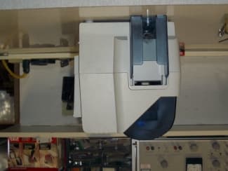
Click to zoom
Application Details
- Equipment Class
- DXX - Part 15 Low Power Communication Device Transmitter
- Date of Grant
- Jun 18, 2006
- Application Purpose
- Original Equipment
- Date of Application
- Jun 18, 2006
- Equipment Note
- Plastic Card Printer
- Frequency Range
- 13.56000000 - 13.56000000
- Country
- United States
Documents & Files
Document Text
Text extracted from the exhibit documents filed with the FCC. Open a document above to read the original.
Users Manual
User’s Manual Zebra ® P430i Card Printer D u a l-S id e d C o l o r 980471-001 Rev. 01P430i User’s Manual1 Foreword This manual contains installation and operation information for the Zebra P430i Card Printers manufactured by Zebra Technologies Corporation, Camarillo, California. Return Materials Authorization Before returning any equipment to Zebra Technologies Corporation for in-warranty or out-of- warranty repair, contact Repair Administration for a Return Materials Authorization (RMA) number. Repack the equipment in the original packing material and mark the RMA number clearly on the outside. Ship the equipment, freight prepaid, to the address listed below: •For USA, Latin America, and Asia / Pacific: Zebra Technologies Corporation Zebra Card Printer Solutions 1001 Flynn Road Camarillo, CA. 93012-8706.USA Phone: +1 (805) 578-5001 FAX: +1 (805) 579-1808 •For Europe and Middle East: Zebra Technologies Corporation Zebra Card Printer Solutions Pittman Way, Fulwood Preston, PR2 9ZD Lancashire, U.K. Phone: +44 - 1 - 772 - 797555 FAX: +44 - 1 - 772 - 693000 2P430i User’s Manual980471-001 Rev. 01 Foreword Copyright Notice © 2005 ZIH Corp. This document contains information proprietary to Zebra Technologies Corporation. This document and the information contained within is Copyrighted by Zebra Technologies Corporation and may not be duplicated in full or in part by any person without written approval from Zebra. While every effort has been made to keep the information contained within current and accurate as of the date of publication, no guarantee is given that the document is error-free or that it is accurate with regard to any specification. Zebra reserves the right to make changes, for the purpose of product improvement, at any time. Trademarks P430i is a trademark and Zebra is a registered trademark of Zebra Technologies Corporation. Windows and MS.DOS are registered trademarks of Microsoft Corp. All other trademarks or registered trademarks are marks of their respective holders. Warranty Information Printers: All Zebra Card Printers are warranted against defects in material or workmanship for twelve (12) months from the purchase date. Proof of purchase or shipment date is required to validate the warranty period. The warranty becomes void if the equipment is modified, improperly installed or used, damaged by accident or neglect, or if any parts are improperly installed by the user. Printheads: Since printhead wear is part of normal operation, the original printhead is covered by a twelve (12) month date. Warranty period begins on purchase date. Note • Products returned must be packaged in the original or comparable packing and shipping container. In the event equipment is not so packaged, or if shipping damage is evident, it will not be accepted for service under warranty. Surface Transportation charges for return to customers in the continental United States is paid by Zebra. Otherwise, Zebra pays CPT (carriage paid to) nearest airport, customer pays customs, duties, taxes, and freight from airport to destination. If Zebra determines that the product returned for warranty service or replacement is not defective as herein defined, the customer will pay all handling and transportation costs. Foreword 980471-001 Rev. 01P430i User’s Manual3 To qualify for this warranty, the printer must be returned to the factory or to an authorized service center. Customers are not required to purchase Zebra supplies (media and/or ribbons) for warranty qualification. If the use of other manufacturer supplies has caused any defect in the printhead for which a warranty claim is made, the user is responsible for Zebra's labor and material charges required to repair the defect. The warranty becomes void if the printhead is damaged; also if it is determined that failure to follow the preventive maintenance schedule listed in the User's Guide has caused defect in the thermal printhead for which a warranty claim is made. Spare Parts: All parts, print heads, maintenance kits, options kits, and accessories are warranted to be free of defects in material and workmanship for 90 days (except where otherwise denoted) from date of purchase. This warranty becomes void if the item is modified, improperly installed or used, or damaged by accident or neglect. Product Disposal Declarations of Conformity For a formal certificate, please contact the Compliance Office at Zebra’s Camarillo facility. Product Disposal Information • Do not dispose of this product in unsorted municipal waste. This product is recyclable, and should be recycled according to your local standards. For more information, please see our web site at: http://www.zebra.com/environment 89/336/EEC modified by 92/31/EEC and 93/68/EEC EMC Directive EN 55022 (1998)RF Emissions control EMC Directive EN 301489-3 V1.4.1 RF Emissions and Immunity for radio equipment EMC DirectiveEN55024 (2001) Immunity to Electro-Magnetic Disturbances 73/23/EEC modified by 93/68/EEC Low voltage Directive EN 60950-1 (2001)Product safety 1999/5/CE R&TTE Directive EN300330-2 V1.1.1Radio Frequency Interferences 4P430i User’s Manual980471-001 Rev. 01 Foreword EUROPE: Norway Only: This product is also designed for IT power system with phase to phase voltage 230V. Earth grounding is via the polarized, 3-wire power cord. FI: “Laite on liitettävä suojamaadoitus koskettimilla varustettuun pistorasiaan” SE: “Apparaten skall anslutas till jordat uttag” NO: “Apparatet må tilkoples jordet stikkontakt” Supplemental Information: This equipment has been tested and found to comply with the limits for a Class A digital device, pursuant to part 15 of the FCC Rules. These limits are designed to provide reasonable protection against harmful interference in a residential installation. This equipment generates, uses, and can radiate radio frequency energy and, if not installed and used in accordance with the instructions, may cause interference to radio communications. Operation of this equipment in a resid…
Text truncated - open the document above for the full version.
Users Manual
14P430i User’s Manual980471-001 Rev. 01 Installation and Setup Installing the Card Cleaning Cartridge Installing the Card Cleaning Cartridge The Card Cleaning Cartridge cleans the cards entering the printer. The Card Cleaning Cartridge consists of a Cartridge Frame and an Adhesive Roller, which are packed together. 1.Remove the Cartridge Frame and the Adhesive Roller from their packaging. Insert the Adhesive Roller into the Cartridge Frame, as shown below. To avoid contamination, always hold the frame and the roller by the ends. . 2.Peel the protective wrapper from the Adhesive Roller. 3.If the printer’s main cover is closed, open it. Locate the area where the Card Cleaning Cartridge will be installed (initially, this area was covered by a warning tape). D ua l-Sid ed Color Card Cleaning Cartridge Mounting Location Installation and Setup Installing the Card Cleaning Cartridge 980471-001 Rev. 01P430i User’s Manual15 4.Locate the slot at the rear of the Card Cleaning Cartridge mounting location; see below. 5.Hold the Card Cleaning Cartridge by the extended “handle” (so the large arrow on the top is pointing away from you). With the cartridge at about a 30 ° angle (pointing downward), insert the lip of the cartridge into the slot, until the cartridge seats against the back wall. Then press the front of the cartridge down until it seats all the way down and latches with an audible “click”. See below. 6.Close the printer’s Main Cover. D u a l- S i d e d C o l o r Card Cleaning Slot Card Cleaning Cartridge in final position 16P430i User’s Manual980471-001 Rev. 01 Installation and Setup Setting the Card Thickness Control Setting the Card Thickness Control The Card Thickness Control is set by the user to adjust the gap as cards enter the printer, to prevent double-feeds (which could cause a jam) or mis-feeds. 1.Open the Card Feeder cover. The cover is hinged; lift it by the lip at the right front corner. 2.The Card Thickness Control Lever is at the front of the left-side opening of the Card Feeder area. Note • Set the Card Thickness Control before loading cards. Note • To reduce contamination and ensure better print quality, minimize the time the Card Feeder cover is open. D u a l - S i d e d C o l o r Card Thickness Control D u a l - S i d e d C o l o r Installation and Setup Setting the Card Thickness Control 980471-001 Rev. 01P430i User’s Manual17 3.There are four detents to set the position of the Card Thickness Control. Slide the Card Thickness Control to the position corresponding to the following: Detent PositionCard Thickness Highest50 mil (1.27 mm) to 60 mil (1.52 mm) 3rd position30 mil (0.76 mm) to 50 mil (1.27 mm) 2nd position20 mil (0.51 mm) to 40 mil (1.02 mm) Lowest10 mil (0.25 mm) to 20 mil (0.51 mm) Note • The overlap in settings above accomodates variations in environmental conditions (especially humidity) and cards from different manufacturers. In general, start at the lowest position and move the lever up until cards feed reliably. Note • “60 mil” (“1.524 mm”) cards may have a significant variation (over 10%) in the actual thickness of the cards; do not use these cards unless each card has been measured to have a thickness less than 66 mil (1.676 mm). 18P430i User’s Manual980471-001 Rev. 01 Installation and Setup Loading Cards Loading Cards This section shows how to load plastic cards into the P430i Printer. The P430i can use cards with a range of thickness from 10 mil (0.25 mm) to 60 mil (1.5 mm). The P430i Printer can also load and print cards fed individually. Information on this is given in the next chapter. The plastic cards generally come in decks of 100 cards; the Card Feeder can hold a full deck of 100 30-mil cards. Cards sometimes will stick together; this can cause mis-feeding or double- feeding. To avoid this, separate the cards before loading, as described in steps 2 through 4 below. 1.If the Card Feeder cover is closed, open it. The cover is hinged; lift it by the lip at the right front corner. Note • Do not mix cards of different thicknesses! Note • DO NOT bend cards or touch print surfaces as this can reduce print quality. The surface of the cards must remain clean and dust free. Always store cards in an enclosed container. Ideally, use cards as soon as possible. Note • For cards with magnetic stripe, refer to Appendix A for loading instructions. Note • To reduce contamination and ensure better print quality, minimize the time the Card Feeder cover is open. D u a l - S i d e d C o l o r D u a l - S i d e d C o l o r Installation and Setup Loading Cards 980471-001 Rev. 01P430i User’s Manual19 2.Remove all wrapping from the card deck. 3.Holding the card deck by the sides, hold it vertically against a flat surface such as a desktop. If the deck is too thick for your hand to hold it comfortably, use about half a deck at a time. 4.Push the stack back and forth to an angle of about 45° from vertical, so as to separate all of the cards. 5.Restore the card stack to its original squared-off condition, and place the cards in the input hopper. 6.Note that there will be a “gap” in the card stack, with several cards lying flat and the cards above angled upward, as shown in the exaggerated drawing below. This is normal and ensures proper feeding. Caution • Do not touch print surfaces of the cards; this can reduce print quality Note • Static charges and edge burrs from the card die-cutting process can render individual cards stuck together with significant adhesion force. These cards must be physically separated from each other before inserting into the feeder; if not separated, feeding or printing problems may occur. 20P430i User’s Manual980471-001 Rev. 01 Installation and Setup Card Output Hopper Card Output Hopper The card output hopper is normally extended to receive the printed cards. The printer may be operated with the card output hopper in its closed position; in this case the cards will not be collected in the output hopper. 1.Pull the card output hopper out to place …
Text truncated - open the document above for the full version.
Users Manual
34P430i User’s Manual980471-001 Rev. 01 Cleaning Card Cleaning Cartridge 6.Replace the Card Cleaning Cartridge into the printer. For detailed instructions, see Installing the Card Cleaning Cartridge on page 14. 7.Close the printer main cover. Note • DO NOT touch the adhesive roller surface that contacts the cards. D u a l - S i d e d C o l o r Card Cleaning Cartridge in final position 980471-001 Rev. 01P430i User’s Manual35 5 Troubleshooting The table on the next page offers causes and solutions to symptoms related to improper operation. Check the table when experiencing any loss of operation or print quality. 36P430i User’s Manual980471-001 Rev. 01 Troubleshooting Problem / DescriptionCause / Solution The LCD Panel displays OUT OF CARDS message. 1. Check for cards in the card feeder. If no cards present, load cards. 2. Check that Card Thickness Control lever is properly adjusted (see Loading Cards in Chapter 2). 3. Press the Panel Button for 1 second. The printing job will restart. The LCD Panel displays OUT OF RIBBON message. 1. Check ribbon. Replace if defective or entirely used. Ribbon will automatically synchronize and printing will restart with a new card. The LCD Panel displays PRINT HEAD OPEN message. 1. Check that Print Head Carriage is closed and latched. If not, close and latch it. The LCD Panel displays MECHANICAL ERROR message. 1. Check that you are using the correct card type (see Technical Specifications). 2. Check that Card Thickness Control lever is properly adjusted (see Loading Cards in Chapter 2). 3. If 2 cards are fed into the printer at the same time: Open cover and remove Card Cleaning Cartridge, empty the Card Feeder, and pull the jammed cards out. Replace the Card Cleaning Cartridge. Remove cards from Card Feeder, separate them as shown in Loading Cards in Chapter 2, and replace. 4. Check that ribbon is loaded correctly. The LCD Panel displays ENCODING ERROR message. 1. Check that you are using the correct magnetic card type (for low or high coercivity encoding). 2. Verify command syntax. 3. Contact Zebra technical support. The LCD Panel displays CLEAN PRINTER message. 1. Printer cleaning required (see Chapter 4). Troubleshooting Print Quality Issues 980471-001 Rev. 01P430i User’s Manual37 Print Quality Issues This section will help you resolve print quality problems. The print quality is dependent on several factors. The two most important factors that will increase your print quality are cleanliness and card stock. To diagnose and fix print quality problems, follow the troubleshooting procedures below: Possible Cause: •Contamination on the card surface. Solutions: •Check that cards are stored in a dust free environment. •Use a different supply of cards. Possible Cause: •Dust inside the printer and/or dirty Cleaning Roller. Solutions: •Perform a Cleaning of the printer (see Chapter 4). •Replace Cleaning Roller (see Chapter 4). Possible Cause: •Ribbon cartridge is not correctly positioned. Solutions: •Ensure that the ribbon is properly rolled onto the ribbon cores of the cartridge and that there are no wrinkles in the ribbon. •Replace ribbon cassette, making sure it locks in place. Example 1 • Small spots appear on the printed card with a non-printed area or a different color. Example 2 • There are non-printing horizontal lines (white) on the card surfaces. 38P430i User’s Manual980471-001 Rev. 01 Troubleshooting Print Quality Issues Possible Cause: •Print Head is dirty. Solution: •Clean the Print Head Possible Cause: •Print Head elements are damaged (e.g., scratched or burnt). Solution: •Call Zebra Customer Service for Print Head replacement information. Possible Cause: •Ribbon has been stored improperly or is damaged. Solution: •Change ribbon and print again. Possible Cause: •Cards may not meet specifications. Solution: •Use a different supply of cards. Possible Cause: •Contrast and/or Intensity may be set to incorrect values. Solution: •Adjust Contrast and/or Intensity values in software. Possible Cause: •Head Settings are too low / high. Solution: •Adjust Head Settings higher / lower. Example 3 • Printing shows very pale, very dark, or inconsistent results Troubleshooting Print Quality Issues 980471-001 Rev. 01P430i User’s Manual39 Possible Cause: •Dust or embedded contamination on elements of the Print Head. Solution: •Perform a Cleaning of the Print Head (see Chapter 4). Possible Cause: •Ribbon cartridge may not be correctly positioned. Solution: •Check that the ribbon is properly rolled onto the ribbon cores of the cartridge. •Replace ribbon cartridge, making sure it locks in place, and print again. Possible Cause: •Ribbon may not be synchronized on the correct color panel position. Solution: •Open the Print Head Carriage, then close it. This will cause the ribbon to re- synchronize. Possible Cause: •Cards may not meet specifications. Solution: •Use a different supply of cards. Possible Cause: •Dust or embedded contamination inside the printer and/or dirty Cleaning Roller. Solution: •Clean the Print Head. •Replace the Cleaning Roller. Example 4 • Printing shows blurry printed image. 40P430i User’s Manual980471-001 Rev. 01 Troubleshooting Print Quality Issues Possible Cause •Ribbon may not be installed in the printer. Solution: •Check for ribbon in the printer. Possible Cause •Cards may not meet specifications. Solution: •Use a different supply of cards. Possible Cause •Print Head elements may be scratched or burnt. Solution •Call Service for Print Head replacement information. Possible Cause •Using the wrong type of ribbon. Solution: •Use only i Series ribbons for full color printing. Example 5 • No printing on the card. Example 6 • Only one panel of a color ribbon prints. Note • For optimum print quality, always keep the Main Cover and the Card Feeder Cover of the printer closed. Troubleshooting Troubleshooting the Ethernet Connection and Adapter 980471-001 Rev. 01P430i User’s Manual41 Troubleshooting the Ethernet Connection and Adapter Resetting to Factor…
Text truncated - open the document above for the full version.
Block Diagram
P430i BLOCK DIAGRAM with Smart Card Options RFID PCBA & ANT 10 MHz 13.56 MHz EXT CONTACT ENCODER I/O PCBA FLIPPER MODULE ~2.4 MHZ RC INTERNAL SMART CARD I/O PCBA GEM+ CONTACT STATION PCBA 13.56MHz COVER OPEN SENSOR FEEDER SENSORS PRINT HEAD ASSEMBLY MAGNETIC ENCODER ASSEMBLY 120/240 AC INPUT & EMI FILTER POWER SUPPLY 24VDC OUT I/O DAUGHTER PCBA CARD SYNC SENSOR RIBBON COLOR SENSOR PCBA DC MOTOR #1 DC MOTOR #2 STEPPER MOTOR FILM & BRACKET SENSOR PCBA CARD FEEDER HID/MIFARE ENCODER MODULE 1.8432 MHz 13.56 MHz LOOP ANTENNA MODULE 24VDC INPUT E-NET I/O USB I/O OPTIONAL CONTACT LESS SMART CARD ENCODERS OPTIONAL GEM+ CONTACT ENCODER OPTIONAL EXTERNAL CONTACT ENCODER EXT CONTACT STATION PCBA SMART CARD I/O I²C BUSS MAIN PCBA LCD DISPLAY ~4 MHz RC 32.00 MHz MCU 25.00 MHz e-net 24.00 MHz USB 14.7456 MHz TPH I²C buss #2 I²C buss #1
Cover Letter(s)
Mr. Ramirez: In order for processing of this application (FCC ID: I28-P430I) to continue, the following issue(s) will have to be addressed: 1) Please clarify the scope of this application. Is certification requested to cover only the RFID transmitter installed in the printer, or is certification also requested for the RFID contactless smartcard? 2) The letter of authorization indicates that CE is authorized to act as an agent for Zebra Technologies at 1001 Flynn Road, Camarillo, CA 93012. However, the grantee code I28 is assigned to Zebra Technologies in Illinois. Please provide a new letter. 3) The sample FCC label shows the grantee code MX5, but the certification is for the grantee code I28. Please correct label. 4) Please indicate the detector function used for the measurement of the fundamental emission and second harmonic. Since the emissions were measured at a distance of 3 meters, and the limit is specified at 30 meters, please also provide your calculations for extrapolating the limit. 5) The data indicates that the frequency of the fundamental emission is at 15.547 MHz, but it appears that the limit shown on the data sheet reflects the 15,848 uV/m limit for the frequency range of 13.553 MHz to 13.567 MHz range, with a 40 dB/decade extrapolation factor applied. The limit for the frequency range of 13.410 to 13.553 MHz is 334 uV/m. Furthermore, the data for the second harmonic indicates a frequency of 27.129 MHz, which would correspond to a fundamental frequency of 13.5645 MHz. Also, the limit used for the second harmonic is incorrect. Please explain these discrepancies. 6) According to section 4.1 of the test report, the printer was operated through its USB port. According to the user’s manual and external photos, there is an option for operating the printer via an Ethernet connection. Were measurements made in this mode of operation? 7) The test report does not describe the operation of the transmitter during the testing, nor does it indicate whether a RFID tag was present during the testing. Please describe the test configuration and operating mode in more detail. 8) Section 5.1 of the test reports shows the grantee code as MX5, and not I28. Please correct. 9) The radiated emission test procedure seems to only describe the test method utilized above 30 MHz (antenna height varied from 1-4 meters, etc.) Please describe in detail the test methodology used for measuring emissions below 30 MHz with a loop antenna. 10) Please provide a block diagram for the device. 11) Please provide a plot of the fundamental frequency, so that band-edge compliance can be verified. 12) Please indicate the type of modulation employed by the transmitter. 13) The internal photos provided do not appear to show where the transmitter is installed in the printer. Please provide additional photos to further illustrate the internal construction of the printer. Also, if a smart card transmitter was present in the printer at the time of test, please provide photos of the card. The item(s) indicated above must be submitted before processing can continue on the above referenced application. Failure to provide the requested information within 60 days of the original e-mail date may result in application dismissal and forfeiture of the filing fee. Also, please note that partial responses increase processing time and should not be submitted. Please upload responses and/or exhibits to the electronic filing website. Your correspondence number is I28-P430I-1. Best regards, Scott McCutchan Operations Manager Compatible Electronics TCB 114 Olinda Drive Brea, CA 92823 (714) 579-0500 Fax (714) 579-1850
Cover Letter(s)
Correspondence NumberMemo I28-P430-I Subject: FCC ID I28-P430I 1)Scope of application is for the RFID transmitter and RFID contactless smartcard. 2) Letter of authorization can be found with the exhibits sent to you. 3) The sample FCC ID label can be found with the exhibits sent to you. 4) Calculations o f the Fundamental limit can be found in appendix E of the test report. 5) Corrections were made to the corrected fundamental reading & can be found in appendix E of the test report. 6) Justification of the test mode o f operation for both Ethernet and USB are explained in section 4 of the test report. 7) Description of how the card printer was operating during the test can be found in section 4 of the test report. 8) Grantee code was corrected and can be found in section 5. 9) Test method used for measuring emissions below 30 MHz. can be found in section 7.1.2 of the tes t report. 10) A new block diagram can be found with the exhibits. 11) Band edge data & plot can be found in appendix E o f the test report. 12) Type of modulation of the transmitter can be found in the P430I description 13) Additional photos can be found with the exhibits sent to you.
External Photos
P430i front view P430i rear view P430i left side P430i right side
Internal Photos
AC Input top view EUT front & cover removed LCD front LCD rear PCB component side no daughter PCB component side with daughter PCB solder side Rear cover removed RFID component side RFID solder side
Internal Photos
RFID PCBA Board RFID PCBA Board RFID PCBA Board RFID PCBA Board
Internal Photos
Smart Card HID Smart Card HID Smart Card HID Smart Card HID
Operational Description
Zebra Technologies P430I Printer Description 10/10/2005 The Zebra P430i is a card printer that can print on both sides of a PVC card in one pass through the printer. The Zebra P430i uses color dye-sublimation ribbons or thermal transfer ribbons to transfer digital images to a PVC card. These cards can be used for identification, loyalty cards, or marketing purposes. Options for this printer include Ethernet, magnetic card encoding, contact and contact-less smart card encoding. Ribbon recognition and security is maintained through RFID technology within the printer. The RFID board and the contactless smartcards use separate transmitters each operating at a frequency of 13.56 MHz in the ISM band. The RFID system uses an I●CODE1 format and conforms to ISO 15693 specifications. The RFID system is contained on a single PCBA which holds the loop antenna, impedance matching network, RF interface IC and digital controller IC. The design is optimized for short range lower power operation. Two types of Contact-less smart cards are supported which require a different modules to be installed. These are HID I-Class and MIFARE format smart cards, which conform to the ISO14443 specification. The system consists of a transceiver module and an antenna module mounted on a small snap-in assembly mounted in the printer top case. The same antenna module with integral matching network is used for both types of smart card systems. The HID I-Class system uses HID OEM50 modules. The iClass OEM50 exciter modulates a 13.56MHz carrier signal in accordance with ISO/IEC 14443-2 and ISO/IEC 15693-2. The modulated carrier is then filtered to suppress harmonics before driving the antenna. The output impedance of the exciter is 50 ohms for driving remote antennas through a coax cable and the impedance matching network of the antenna matches the impedance for maximum power transfer. The OEM50 generates a 13.56MHz signal, referred as the carrier, at the input of the reader antenna that is transmitted in the form of magnetic fields. The magnetic field generates a voltage across the card antenna and when that voltage reaches sufficient magnitude the chip on the card will power up and begins communicating with the reader by modulating the impedance seen by its antenna. The changing impedance on the card changes the mutual inductance between the antennas, which in turn, causes a change in the magnitude of the exciter signal that drives the reader antenna. It is this change in the exciter signal amplitude that allows reverse communications form the contact-less card. The MIFARE system uses a Phillips supplied module to support the MIFARE encoding format. The operation is similar to the I-Class described above and conforms to the ISO14443 specification.
Schematics
Q3L-II03,:IS 3SIkI~I-B.O SS3"INfl :S3.LON Oil 6f LO NOTES: UNLESS OTHERWISE SPECIFIED SCHEMATIC P330i, RFID READER NOTES: UNLESS OTHERWISE SPECIFIED SCHEMATIC P330i,CPU MAIN A D0 D1 D2 D3 D4 D5 D6 D7 E K R/W RS VDD VL VSS HDM16116L-L RA1/AN1 RA7/OSC1/CLKI RA6/OSC2/CLKO RA5/~MCLR/VPP RA4/AN4/TOCKI RA3/AN3/VREF+ RA2/AN2/VREF- RA0/AN0 VDD1VDD2 VSS1VSS2 RB0/INT RB1/SDI/SDA RB2/SDO/CCP1 RB3/CCP1/PGM RB4/SCK/SCL RB5/~SS RB6/T1OSO/T1CKI/PGC RB7/T1OSI/PGD APPR THESE DRAWINGS AND SPECIFICATIONS SHALL NOT BE DISCLOSED, ANY PURPOSE WHATSOEVER, EXCEPT REPRODUCED, COPIED, OR USED FOR ON A CONFIDENTIAL BASIS, AND ARE FURNISHED FOR EVALUATION ONLY ZEBRA TECHNOLOGIES CORPORATION, ARE THE EXCLUSIVE PROPERTY OF SAVEDFIRST USE OF ENGR DATE APPR TITLE DWG SIZEDWG NO D A B C A B C D ECO NODATEREVDESCRIPTIONDRAWN REVISIONS D DRAWN SHEET WITH THE PRIOR WRITTEN CONSENT OF ZEBRA TECHNOLOGIES CORPORATION 87654321 87654321 09 DOCUMENTATION CORRECTION ONLY09 08 07 JB MUST BE CONNECTED TO METAL AROUND GLASS ASSEMBLY NOTES: E-GROUND INSTALLED STARTING AT PIN 4. INSTALLED STARTING AT PIN ONE. J1A IS A 10 PIN CONNECTOR J1A and J1B CONNECTORS J1B IS A 10 PIN CONNECTOR - OBSERVE J1A AND J1B MOUNTING CONFIGURATION. PROGRAMMING NOTES: 09/02/05J COOKE REV P330i P1XXi J1A INSTALLED ONLY WITH P1XXi. J1B INSTALLED ONLY WITH P330i. DNI NOTES: LAYOUT NOTES: - INSTALL ALL COMPONENTS EXCEPT THOSE INDICATED WITH NU. - KEEP BYPASS CAPS CLOSE TO THE COMPONENTS THEY ARE ASSOCIATED WITH. - KEEP R5 CLOSE TO U1 PIN 4. - POUR COPPER TOP AND BOTTOM IN ALL FREE BOARD AREAS. AND ATTACH TO EARTH GROUND. R9 330 R8 82 R11 82 R2 120 LCD-MODULE & FEED SW. 02 03 04 05 07-21-03 07-22-03 07-29-03 02-06-04 R.ROSE R.ROSE R.ROSE R.ROSE PRELIMINARY DESIGN - CHANGE RB3/RB6 FOR PWM. ADD CAPS, ADD MICRODRIVER,CHANGE FET/BJT,COMP VALUES ADD FALCON PUSHBUTTON, REMOVE DIODE,CHANGE C2 JBPRELIMINARY DESIGN - CONNECTOR, JUMPER, CIRCUIT CHANGE R.ROSE 403411-101 11 9-2-2005_11:10 R.ROSE XXXXX P120/110 0107-09-03R.ROSEJB JB JB JB PRELIMINARY DESIGN 6-09-04R.ROSE06ADD ESD PROTECTION DEVICES. P1 10 9 8 7 6 5 4 3 2 1 P330I J1B 1 2 3 4 5 6 7 8 9 10 J1A P1XXI 12 34 S2 B3SN-3012 FEED_SWITCH 6 7 8 2 3 45 1 VSN3 PENDING V5.5MLN41206 1 54 3 2 8 7 6 V5.5MLN41206 PENDING VSN2 6 7 8 2 3 45 1 VSN1 PENDING V5.5MLN41206 R10 15.0K 1/10W C14 1UF 16V C3 100PF 16V C11 .1UF 16V 12 4 3 S1 16 6 20 19 18 17 15 14 13 12 11 10 9 8 7 5 4 3 2 1 U1 PIC16F818 SSOP-20 R1 10.0K +5V R6 470 R5 10.0K 7 8 9 10 11 12 13 14 6 5 4 2 3 1 U2 16V 100PF C10 +5V +5V +5V 16V .1UF C15 16V .1UF C1 C13 .1UF 16V +5V +5V+5V +5V +5V 16V 100PF C4C7 100PF 16V C9 100PF 16V 1 2 3 Q1 FDN359AN 16V 100PF C5C6 100PF 16V C2 10UF 10V/16V EGND EGND EGND ICSP_PGD SPI_SS SDI_PGM SPI_SDO SPI_SDI SDI_ICSP_SCK MRST <DATECHKD> FILENAME SIZENUMBER of SHEET REV LAST TOUCHED Zebra Technologies Corporation 1001 Flynn Road Camarillo, CA 93012 www.zebra.com PROPRIETARY INFORMATION THE INFORMATION CONTAINED HEREIN PROHIBITED EXCEPT AS SPECIFIED IN WRITING BY ZEBRA TECHNOLOGIES CORP. IS PROPRIETARY TO ZEBRA TECHNOLOGIES CORP. ANY REPRODUCTION IN WHOLE OR IN PART, DISCLOSURE, OR USE OF THIS DOCUMENT IS EXPRESSLY RESPONSIBLE ENGINEERDATE CHECKED TITLE DescriptionRevByEO# 1 A 1 A 432 B C D B C D 432 B P330I, SMART …
Text truncated - open the document above for the full version.
Contact Information
Applicant
Jay Cadiz(Sr. Manager, Regulatory)
Technical Contact
Compatible ElectronicsReynald O Ramirez
[email protected]818-597-0600
2337 Troutdale Drive · Agoura, California · United States
Test Firm
Compatible Electronics, Inc.Jeff Klinger
Technical Specifications
| # | Rule Parts | Frequency Range | Power Output |
|---|---|---|---|
| 1 | 15C | 13.56 MHz - 13.56 MHz | - |
Other Applications from Zebra Technologies Corporation
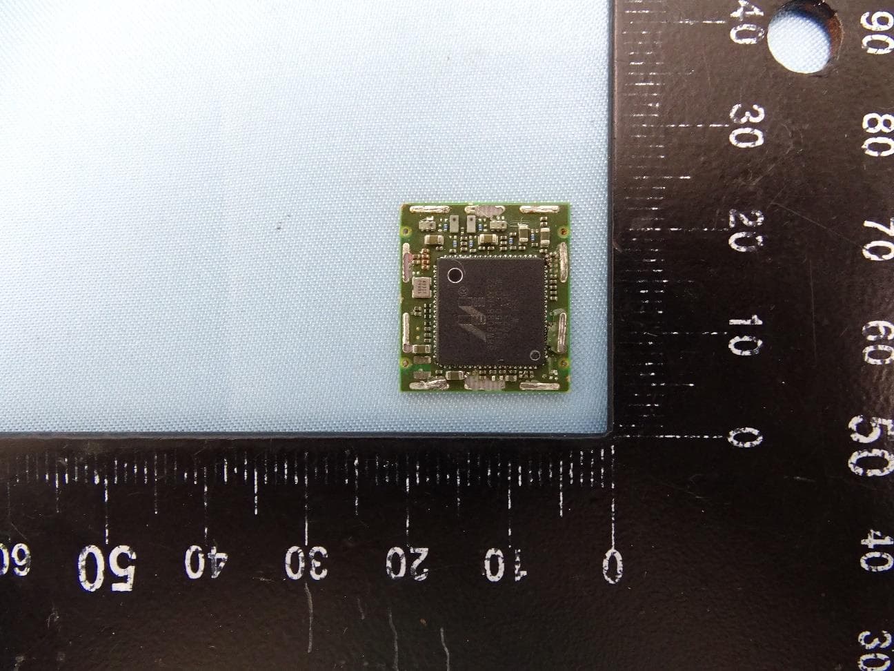
I28-WYSBHVDXP
May 19, 2021WLAN/BTLE module
Equipment Class
DTS - Digital Transmission System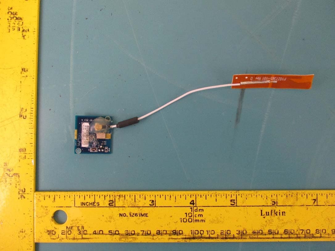
I28-EYSNSNZWWZ1
May 04, 2021BT5 Radio Module
Equipment Class
DTS - Digital Transmission System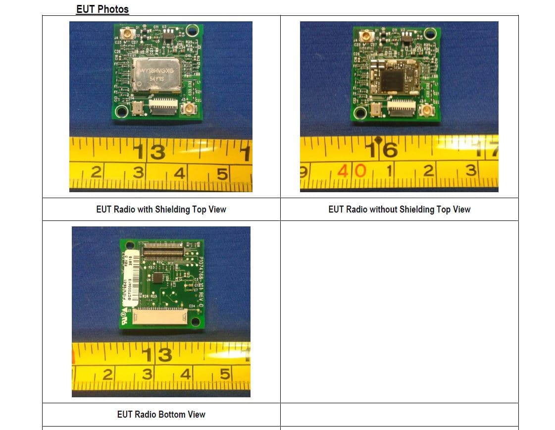
I28MD-FXLAN11AC
Nov 22, 2015Wireless 802.11ac + Bluetooth Module
Equipment Class
DSS - Part 15 Spread Spectrum Transmitter
I28MD-ZBRBLE
Nov 19, 2015Bluetooth Low Energy Module
Equipment Class
DTS - Digital Transmission System
I28MD-ZBR7BTLE
Jan 19, 2015Bluetooth 4.0 LE Module
Equipment Class
DSS - Part 15 Spread Spectrum Transmitter