I28-P430I-MIFARETHERMAL CARD PRINTER
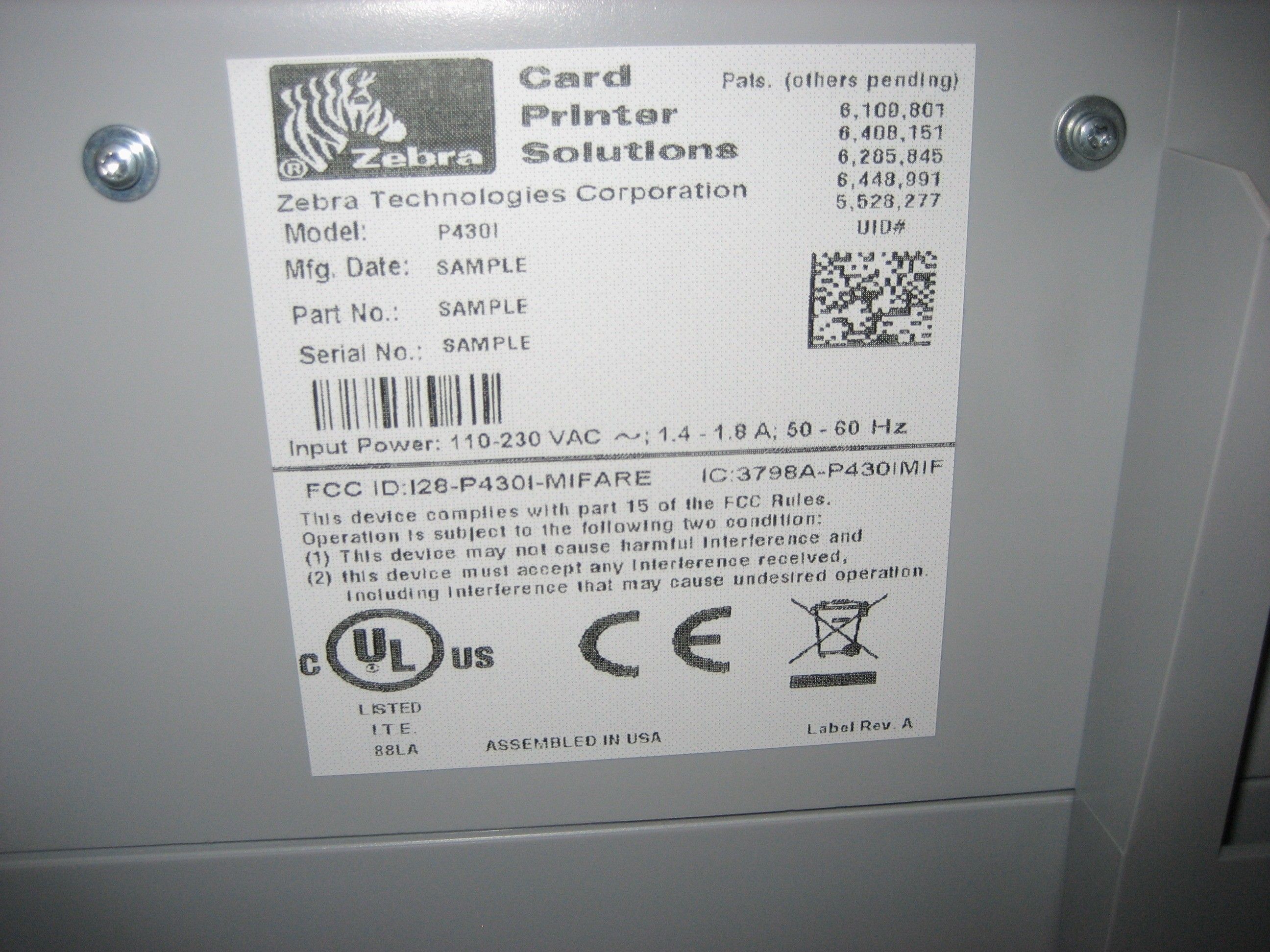
Zebra Technologies Corporation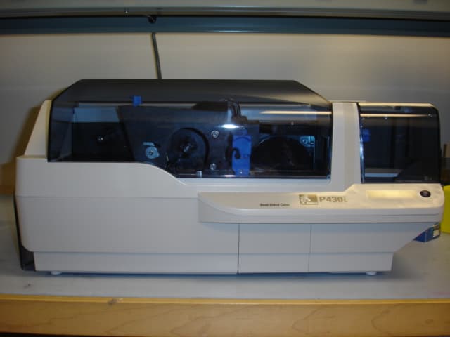
Click to zoom
Application Details
- Equipment Class
- DXX - Part 15 Low Power Communication Device Transmitter
- Date of Grant
- May 07, 2007
- Application Purpose
- Original Equipment
- Date of Application
- May 06, 2007
- Equipment Note
- THERMAL CARD PRINTER
- Frequency Range
- 13.56000000 - 13.56000000
- Country
- United States
Documents & Files
Document Text
Text extracted from the exhibit documents filed with the FCC. Open a document above to read the original.
Users Manual
980470-001 Rev. A User’s Manual Zebra ® P430i Card Printer D ual-Sid ed Color 980470-001 Rev. BP430i User’s Manuali Foreword This manual contains installation and operation information for the Zebra P430i Card Printers manufactured by Zebra Technologies Corporation, Camarillo, California. Return Materials Authorization Before returning any equipment to Zebra Technologies Corporation for in-warranty or out-of-warranty repair, contact Repair Administration for a Return Materials Authorization (RMA) number. Repack the equipment in the original packing material and mark the RMA number clearly on the outside. Ship the equipment, freight prepaid, to the address listed below: •For USA, Latin America, and Asia / Pacific: Zebra Technologies Corporation Zebra Card Printer Solutions 1001 Flynn Road Camarillo, CA. 93012-8706.USA Phone: +1 (805) 578-5001 FAX: +1 (805) 579-1808 •For Europe and Middle East: Zebra Technologies Corporation Zebra Card Printer Solutions Pittman Way, Fulwood Preston, PR2 9ZD Lancashire, U.K. Phone: +44 - 1 - 772 - 797555 FAX: +44 - 1 - 772 - 693000 iiP430i User’s Manual980470-001 Rev. B Foreword Copyright Notice © 2006 ZIH Corp. This document contains information proprietary to Zebra Technologies Corporation. This document and the information contained within is Copyrighted by Zebra Technologies Corporation and may not be duplicated in full or in part by any person without written approval from Zebra. While every effort has been made to keep the information contained within current and accurate as of the date of publication, no guarantee is given that the document is error-free or that it is accurate with regard to any specification. Zebra reserves the right to make changes, for the purpose of product improvement, at any time. Trademarks P430i is a trademark and Zebra is a registered trademark of Zebra Technologies Corporation. Windows and MS.DOS are registered trademarks of Microsoft Corp. All other trademarks or registered trademarks are marks of their respective holders. Product Disposal Product Disposal Information • Do not dispose of this product in unsorted municipal waste. This product is recyclable, and should be recycled according to your local standards. For more information, please see our web site at: http://www.zebra.com/environment Foreword 980470-001 Rev. BP430i User’s Manualiii Declarations of Conformity For a formal certificate, please contact the Compliance Office at Zebra’s Camarillo facility. EUROPE: Norway Only: This product is also designed for IT power system with phase to phase voltage 230V. Earth grounding is via the polarized, 3-wire power cord. FI: “Laite on liitettävä suojamaadoitus koskettimilla varustettuun pistorasiaan” SE: “Apparaten skall anslutas till jordat uttag” NO: “Apparatet må tilkoples jordet stikkontakt” FCC Regulations Model P430i has been tested and found to comply with the limits for a Class A digital device, pursuant to Part 15 of the FCC Rules. These limits are designed to provide reasonable protection against harmful interference when the equipment is operated in a commercial environment. This equipment generates, uses, and can radiate radio frequency energy and, if not installed and operated in accordance with the P430i User’s Manual, may cause harmful interference to radio communications. Operation of this equipment in a residential area is likely to cause harmful interference in which case the user will be required to correct the interference at his own expense. Pursuant to Part 15.21 of the FCC Rules, any changes or modifications to this equipment not expressly approved by Zebra may cause harmful interference and void the FCC authorization to operate this equipment. FCC Radiation Exposure Statement (applicable to 15.247 device only) This equipment complies with FCC radiation exposure limits set forth for an uncontrolled environment. This equipment should be installed and operated with minimum 20 cm between the radiator and your body. This transmitter must not be collocated or operating in conjunction with any other antenna or transmitter unless authorized to do so by the FCC. Industry Canada Notice This device complies with Industry Canada ICES-003 class A requirements. Cet equipement est conforme a l’ICES-003 classe A de la norm Industrielle Canadian. 89/336/EEC modified by 92/31/EEC and 93/68/EEC EMC Directive EN 55022 (1998)RF Emissions control EMC Directive EN 301489-3 V1.4.1RF Emissions and Immunity for radio equipment EMC DirectiveEN55024 (2001) Immunity to Electro-Magnetic Disturbances 73/23/EEC modified by 93/68/EEC Low voltage Directive EN 60950-1 (2001)Product safety 1999/5/CE R&TTE Directive EN300330-2 V1.1.1Radio Frequency Interferences ivP430i User’s Manual980470-001 Rev. B Foreword P430i Printer Model The Zebra Product Number tells a story: Here is a quick review of the Zebra Card Printer Series numbering and lettering system to help you. Model numbers include identifiers that specify options using the following lettering conventions: Icons Throughout this manual, different icons highlight important information, as follows: Part NumberDescription P 4 3 0 i - _ _ _ _ _ - _ _ _ Base Printer P430i Color Card Printer _ _ _ _ _ - 0 _ _ _ _ - _ _ _ _ _ _ _ _ - B _ _ _ _ - _ _ _ _ _ _ _ _ - C _ _ _ _ - _ _ _ _ _ _ _ _ - D _ _ _ _ - _ _ _ _ _ _ _ _ - E _ _ _ _ - _ _ _ _ _ _ _ _ - F _ _ _ _ - _ _ _ _ _ _ _ _ - H _ _ _ _ - _ _ _ Smart Card Options None Contact Encoder Contact encoder & HID iCLASS Contact encoder & MIFARE contactless Contact station HID iCLASS MIFARE contactless _ _ _ _ _ - _ 0 _ _ _ - _ _ _ _ _ _ _ _ - _ M _ _ _ - _ _ _ Magnetic Encoder None Yes (select defaults below) _ _ _ _ _ - _ _ 0 _ _ - _ _ _ _ _ _ _ _ - _ _ 1 _ _ - _ _ _ _ _ _ _ _ - _ _ 3 _ _ - _ _ _ Magnetic Encoder Defaults None Stripe Down, HiCo Stripe Up, HiCo _ _ _ _ _ - _ _ _ 0 _ - _ _ _ Memory Expansion None _ _ _ _ _ - _ _ _ _ A - _ _ _ _ _ _ _ _ - _ _ _ _ C - _ _ _ Interface USB Only USB and Ethernet _ _ _ _ _ - _ _ _ _ _ - I _ _ _ _ _ …
Text truncated - open the document above for the full version.
Users Manual
Installation and Setup Unpacking the Printer 980470-001 Rev. AP430i User’s Manual9 b.Locate the Print Head protection pad and the Card Cleaning Cartridge location tape (see below). Remove the tape. c.Release the Print Head Carriage by pushing the Print Head Carriage Latch to the left, and raise the Print Head Carriage. It will remain open at about a 45 ° angle. I N S T A L L Remove me Print Head P rotection Pad Card Cleaning Cartridge Location Tape Print Head Carriage Latch Dual-Sid ed Color 10P430i User’s Manual980470-001 Rev. A Installation and Setup Installing the Print Driver Software and Setting Driver Options d.Remove the print head protection pad. Keep the pad, as well as the other packing material and the shipping carton, in case the printer is shipped or moved. If the original material is lost, a replacement Shipping Kit can be ordered from your reseller. Installing the Print Driver Software and Setting Driver Options Printing with the P430i Printer requires the Windows Printer Driver and your card design/issuing software or printer command level programming through the printer interface. The P430i Card Printer can be used with any Windows 2000 or Windows XP computer, using the drivers provided on CD with the printer. This section contains information on the printing of a sample card in color (using the 5-panel color ribbon YMCKO and the Windows Printer Driver). Installing the P430i Print Driver To install the P430i Printer Driver automatically on all Operating Systems, use the Zebra Install Wizard. The Install Wizard will walk you through the appropriate installation steps. The Wizard will: •Automatically launch when the driver CD is inserted. •From the main menu of your documentation CD, select your desired language and then select “DRIVERS” from the subsequent menu. The Install Wizard will walk you through the appropriate steps. Note • If updating the printer driver from a previous version, before installing the updated printer driver version, always delete the existing version from your computer. Note • Ensure that you have administrative privileges to perform this installation, or contact your IT department. D u al-Si d ed C olo r Installation and Setup Loading a Ribbon 980470-001 Rev. AP430i User’s Manual11 •Delete previous versions of the driver and clean up any necessary Registry entries. You must select “Remove” from the install options to remove any previous driver versions. Loading a Ribbon i Series Printers require the use of i Series ribbons for full color printing. The Resin Thermal Transfer and Dye Sublimination ribbons for P430i are specifically designed for your P430i Printer. 1.Place the printer power switch in the OFF (0) position. 2.If the printer’s Main Lid is closed: a.Open the printer’s Main Lid; lift it by the lip at the bottom front as shown in the figure below left. b.Raise the Print Head Carriage by pressing the release latch to the left (toward the output hopper) and lifting as shown below to about a 45 ° angle. The Print Head Carriage will stay in that position, as shown at the right below. Electrostatic Discharge Caution • DO NOT TOUCH the Print Head or the electronic components on the Print Head Carriage. Discharges of electro-static energy that accumulate on the human body or other surfaces can damage the Print Head or other electronic components used in the printer. Note • Avoid any direct contact with the print head to prevent transfer of oils or contamination. Outside of normal operation, only the Zebra-approved cleaning materials should come in contact with the print head. D u a l-S id e d C o lo r D u a l-S id e d C o l o r 12P430i User’s Manual980470-001 Rev. A Installation and Setup Loading a Ribbon 3.Locate the Ribbon Supply Spindle and the Ribbon Take-up Spindle (see above). Load ribbon onto the supply spindle (under the print head carriage) flange side in, and load the empty core (with tape attached) onto the take-up spindle. Make sure the ribbon comes off the top of the supply spindle and feeds to the top of the take-up spindle. Dual-Sided Col or Ribbon Supply Spindle Ribbon Take-up Spindle D u a l-S id e d C o lo r Flange Supply Spool Ta k e - u p Spool Installation and Setup Loading a Ribbon 980470-001 Rev. AP430i User’s Manual13 4.Gently press the print head carriage down until it is fully lowered, as shown below. Very little force is neccessary to perform this step. Note • During normal operation (with power connected and turned on), the ribbon would automatically synchronize when the Print Head is restored to its fully-down position. The ribbon would be identified and the corresponding parameters sent to the driver. Since power is not connected at this point in the Installation and Setup Procedure, nothing will happen when the Print Head Carriage is closed. The ribbon will synchronize when power is turned on. Caution • Do not touch the print head if the printer has been in service within the last 10 minutes. It could be very hot and cause a burn. Electrostatic Discharge Caution • A static discharge is possible if you touch any exposed metal parts. Use of an anti-static wrist strap or comparable anti-static protection is required. D ua l-Sid ed Co lor D u a l-S id ed C olo r 14P430i User’s Manual980470-001 Rev. A Installation and Setup Installing the Card Cleaning Cartridge Installing the Card Cleaning Cartridge The Card Cleaning Cartridge cleans the cards entering the printer. The Card Cleaning Cartridge consists of a Cartridge Frame and an Adhesive Roller, which are packed together. 1.Remove the Cartridge Frame and the Adhesive Roller from their packaging. Insert the Adhesive Roller into the Cartridge Frame, as shown below. To avoid contamination, always hold the frame and the roller by the ends. . 2.Peel the protective wrapper from the Adhesive Roller. 3.If the printer’s Main Lid is closed, open it. Locate the area where the Card Cleaning Cartridge will be installed (initially, this area was covered by a warning tape). D ua l-Sid…
Text truncated - open the document above for the full version.
Users Manual
Installation and Setup Printing a Test Card 980470-001 Rev. AP430i User’s Manual23 Printing a Test Card With ribbon and cards loaded, your P430i Printer is ready to print. To check the operation of the printer, you should print a test card. (Printing a test card does not require that the printer be connected to your computer or network, but power must be applied.) 1.Set the printer’s power switch (on the back of the printer) to the OFF ( O ) position. 2.While pressing the Printer’s front panel button (next to the LCD display panel), switch the printer ON ( | ). 3.Hold the panel button until the LCD display panel reads “SELF TEST”. 4.Release the panel button, and the test card will print. This is an example of the test card: Packing the P430i Printer for Shipment If the P430i Printer is to be shipped, it is important to use the original packing and shipping material to prevent damage to the Printer. If the original material is lost, a replacement Shipping Kit can be ordered from your reseller. 1.Remove cards in the card feeder: a.While the printer still has power applied and is turned on, and is still connected to the host computer, remove cards from the card feeder. The last card may be difficult to remove. If so, use the Eject Card command available through the driver on the host computer to eject the last card that is staged in the feeder. b.Close the Card Feeder Cover. Note • The specifics of the shipment and the printer’s condition may influence which of the following steps are followed; common sense should prevail. Caution • Do not physically pull the last card out of the feeder staging area. This could damage the printer and void the warranty, as well as damage the card. PRINTER: P430i Serial N°: XXXXX Firmware: XXXXXXX Head resistance: XXXX Offset: XXXX-XXXX EC:XX Printing counter: XXXXX 300 dpi PLASTIC CARD PRINTER TEST CARD 24P430i User’s Manual980470-001 Rev. A Installation and Setup Packing the P430i Printer for Shipment 2.If the printer still has power applied and is turned on, and is still connected to the host computer, set the printer’s power switch (on the back of the printer) to the OFF ( O ) position, and disconnect the interface and power cables to the printer. 3.Open the Main Lid. Open the Print Head Carriage and remove the Ribbon. (If you wish to save the ribbon for future use, you may want to put it in a plastic bag for storage.) 4.Insert the print head protection pad, and close the Print Head Carriage. Remove the Card Cleaning Cartridge and place it in the upper foam insert. Close the Main Lid. 5.Slide the Output Hopper in all the way against the Printer. 6.Place the Printer in its protective plastic bag. 7.Place the lower foam insert in the lower part of the shipping carton. 8.Use both hands to carefully place the Printer into the recess in the lower foam insert. 9.Place the upper foam insert onto the Printer and gently press it down so it makes a snug fit on the Printer; the top of the upper foam insert should be even with the upper edge of the lower part of the shipping carton. 10.Slide the upper part of the shipping carton down over the lower part. 11.Insert and close the handles/latches. 980470-001 Rev. AP430i User’s Manual25 3 Printing a Card Printing with the P430i Card Printer is similar to printing with any other printer in a Windows environment. •The Printer Driver Software is installed on your computer (see Chapter 2). •The P430i Printer is connected to the power source and the computer (see Chapter 2). •The P430i Printer is selected by either the Operating System or the appropriate application software program. •Printer Properties are set (the factory default values will be appropriate for many applications). •Card printing is directed by the appropriate application software program. Setting Printer Properties Printer Properties can be set either at the Operating System level or within the application software program used for printing cards. Preferences settings can configure the P430i Card Printer for Landscape (wide) or Portrait (tall) printing orientation, and allow the user to verify that the desired ribbon is installed in the printer. (Monochrome ribbons are selected via the drop-down menu.) If the P430i Printer includes the optional magnetic card stripe encoder, encoding parameters and coercivity can be set. Printer cleaning can be initiated from the Tools window (printer cleaning can also be initiated at the printer; see Chapter 4). Also from the Tools window, the Test Card can be selected from several pre-loaded styles. Note • In the following description of setting Printer Properties, only those properties and options that are suitable for being set by the User are described. The User should not make selections or set parameters unless they are specifically described in this section 26P430i User’s Manual980470-001 Rev. A Printing a Card Printing a Sample Card “Single Feed Options” allows Disabling or Enabling Single Feed Support. •If “Disable Single Feed Support” is selected, when the P430i Card Printer runs out of cards in the feeder, the LCD display will read OUT OF CARDS. To continue, press the panel button. •If “Enable Single Feed Support” is selected, when the P430i Card Printer runs out of cards in the feeder it will wait until a card is inserted in the single-card slot or cards are loaded in the feeder, and then will automatically continue. Printing a Sample Card Sample card designs are installed with the printer driver. Sample cards require Microsoft Word or Microsoft P aint application software. The cards are accessed via the Start menu. Select Start, select Programs, select Zebra Card Printers, and select a sample card, or follow the directions below to design a card. Follow these steps to design and print your first card: 1.Launch Microsoft Word Software. Depending on your computer configuration this may be done by double-clicking an icon on your desktop, or by clicking the Windows Start icon, selecting Programs, and navigating to M…
Text truncated - open the document above for the full version.
Cover Letter(s)
Apr 26, 2007 Federal Communication Commission 7435 Oakland Mills Road Columbia, MD 21046 RE: FCC ID: I28-P430I-MIFARE TIMCO Engineering, Inc. 849 NW State Road 45 Newberry, FL 32669 To Whom It May Concern: This letter is to ascertain that the Zebra’s Card Printer P430i has been the unit used for conducting FCC compliance testing. If you have any question or concerns, please contact me. Sincerely, George Anjargolian Compliance Manager
Cover Letter(s)
April 26, 2007 To: Federal Communications Commission 7435 Oakland Mills Road Colubia, MD Dear Examiner: Zebra Technologies Corporation is submitting this petition to avoid the possibility of any inadvertent disclosure of AWID proprietary information as a result of document submission to the Federal Communications Commission (FCC). Zebra Technologies Corporation hereby requests confidentiality with regard to the following documents in the filling package for equipment approval identified by FCC Identification Number: I28-P430I-MIFARE as provided under FCC Section 0.459. - P430i-Block Diagram - 404361G-101A (Main PCBA Schematic) - 402932-001A (RFID PCBA Schematic) - 402332-000_C (Flipper PCBA Schematic) - G8378000-001-SCH (Mifare Radio Schematic) It is the opinion of Zebra Technologies Corporation that disclosure of this information will result in significant loss of market competitiveness, and revenue. This information should therefore be kept confidential. Sincerely, George Anjargolian Compliance Manager Zebra Technologies, CPS Division 805-578-1340
External Photos
P430i External View Front View Rear View Right View Left View
Internal Photos
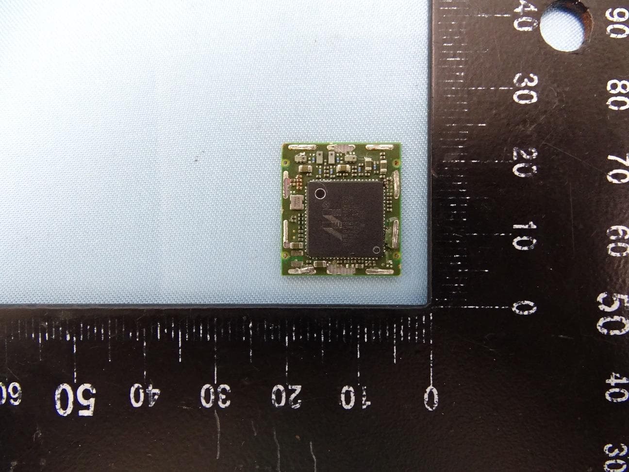
P430i Internal View Cover Off front View Cover off Rear View Ethernet Board Top View Ethernet Board Bottom View Flipper Board Top View Flipper Board Bottom View Mifare radio and antenna Top View Mifare radio and antenna Bottom View RFID Radio board Top View RFID Radio board Bottom View Main Board 1 with USB Top View Main Board 1 with USB Bottom View
Operational Description
GemProx-Module Easy-to-use contactless technology Cost-effective smart card interfaces for the growing contactless market A complete range of products GemProx is the name of the Gemalto range of contactless interfaces. It includes OEM couplers, packaged readers, chip sets and Development Kits. A macro component for hand-held terminals The GemProx-Module is an OEM coupler which embeds all the key components of a very small size contactless interface: 3 cm x 3 cm. It is based on the Gemalto GemProx Chipset High Speed. This coupler can be seen as macro component that is plugged on the mother Printed Circuit Board. Consequently, GemProx-Module is well suited for hand-held terminals such as POS terminals, PDAs or any other portable devices. It also allows the user to turn the RF field off, when not in operation, in order to save battery operating life. The markets targeted are the Proximity Payments, Identity, Access Control and Mass Transit. Technical support An external antenna is connected to GemProx-Module. Gemalto supplies off-the-shelf antennas but also provides: • the appropriate documentation to help its customers to design their own antenna • the technical support to get PayPass, ExpressPay, FIPS 201 / PIV certifications or Electro-Magnetic Compatibility approvals. GemProx-Module OEM coupler Easy to use With GemProx, the contactless technology has now reached the same level of accessibility as the contact one. The application software is dramatically simplified by the use of a high level command set, API library and PC/SC v2.0 driver. Automatic operating modes such as the card insertion / removal, the PayPass card recognition algorithm or the Mifare ® Application Directory (MAD) are implemented on-board and provide the highest possible performances. Market standards and interoperability GemProx technology is fully compliant with the ISO 14443 A and B standard. The T=CL protocol is handled directly by the reader. The Mifare protocol and security scheme are also supported. GemProx readers are ranked among the very best readers in terms of interoperability, thanks to the unique experience of Gemalto both in smart card and reader technologies. www.gemalto.com Specifications Contactless card interface • Operating frequency: 13.56 MHz • Embedded ISO 14443–4 T=CL protocol • Baud rate: 106 Kbps to 848 Kbps • Reading distance: up to 10 cm depending on antenna size • Remote antenna (not included): Antenna connection distance up to 50 cm Host interface • Type of interface: RS232 - TTL levels • Protocol: GBP • Baud rate: 1.2 Kbps to 460 Kbps • Option: Wiegand 32 bits (Mifare and type A cards) External SAM interfaces • Number of SAM interfaces: 4 • ISO 7816 –1 to –3, T=0, T=1 protocols • SAM power supply: +5 VDC +/- 10% • Baud rate: 9.6 Kbps to 115 Kbps Power supply • Voltage: +5 VDC +/- 10% • Current: 200 mA • Low power management functions Other features • Output signals for 3 remote LED indicators and one remote buzzer • Dimensions: 31 mm x 31 mm x 9 mm • Weight : 6 g Main functions • Read/write the following Smart Cards: − ISO 14443 A, B, T=CL cards − Mifare ® cards (including DESFire) − SR176, SRIX512 and SRIX4K − Other cards on request • High level command set • Firmware up grade in Flash memory • Mifare ® Application Directory (MAD) • PayPass, Visa contactless and ExpressPay level 1 compliance • ICAO and FIPS 201 / PIV specifications compliance • Card insertion/removal detection • E-purse command set • Self test Associated tools • GemProx Development Kit • PC/SC v2.0 driver for Windows 2000/XP • C language source code API • Firmware download tools Environment • Operating temperature range: -20 °C to +70 °C (-4 °F to +158 °F) • Storage temperature range: -40 °C to • +85 °C (-40 °F to +185 °F) • Humidity: 0 % to 95 % non condensing • EMC: 89/336/CEE • Safety: UL 1950, cUL CSA 950, EN 60950 • MTBF: 800,000 H at +20 °C Gemalto services Gemalto is recognized as the world’s leading supplier of Smart Cards readers (Frost & Sullivan 2006). Gemalto is an active participant to international standardization groups (ISO, PC/SC, etc.) and offers its unique experience in consulting services such as: Security schemes, interoperability issues, test specifications and tools, feasibility analysis, demonstrations. For payment applications, Gemalto can take in charge the PayPass and ExpressPay certifications of the equipment that embeds GemProx-Module and its antenna. Information subject to change without prior notice
Operational Description
Zebra Technologies P430I Printer Description 04/25/2007 The Zebra P430i is a card printer that can print monochrome or full color images on both sides of a PVC card in one pass through the printer. The Zebra P430i uses color dye-sublimation ribbons or thermal transfer ribbons to transfer digital images to a PVC card. These cards can be used for identification, loyalty cards, or marketing purposes. Options for this printer include Ethernet, magnetic card encoding, contact and contact-less smart card encoding. Ribbon recognition and security is maintained through RFID technology within the printer. The RFID board and the contactless smartcards use separate transmitters each operating at a frequency of 13.56 MHz in the ISM band. The RFID system uses an I●CODE1 format and conforms to ISO 15693 specifications. The RFID system is contained on a single PCBA which holds the loop antenna, impedance matching network, RF interface IC and digital controller IC. The design is optimized for short range lower power operation. Contact-less smart cards are supported using the popular MIFARE format smart cards, which conform to the ISO14443 specification. The system consists of a transceiver module and an antenna module mounted in the printer case. The antenna module with integral matching network connects via coaxial cable and MMCX connector to the transmitter module. The Mifare Contact Less reader uses a GemAlto GemProx module. The GemAlto GemProx exciter modulates a 13.56MHz carrier signal in accordance with ISO/IEC 14443 A&B and ISO/IEC 15693-2. The modulated carrier is then filtered to suppress harmonics before driving the antenna. The output impedance of the exciter is 50 ohms for driving remote antennas through a coax cable and the impedance matching network of the antenna matches the impedance for maximum power transfer. The OEM50 generates a 13.56MHz signal, referred as the carrier, at the input of the reader antenna that is transmitted in the form of magnetic fields. The magnetic field generates a voltage across the card antenna and when that voltage reaches sufficient magnitude the chip on the card will power up and begins communicating with the reader by modulating the impedance seen by its antenna. The changing impedance on the card changes the mutual inductance between the antennas, which in turn, causes a change in the magnitude of the exciter signal that drives the reader antenna. It is this change in the exciter signal amplitude that allows reverse communications form the contact-less card. The GemProx module MIFARE system is based upon a Phillips RF ASIC to support the MIFARE encoding format, more detail data is available on the Phillips website and in the attached G8378000-001 data sheet.
Test Report
TEST REPORT FROM FOR Zebra Technologies Corp. Thermal Card Printer Model: P430i TO 47 CFR 15.225:2006 & RSS-210 Issue 6:2005 Test Report Serial No.: SL07041702-ZBR-022/P430i This report supersedes None Remarks: Equipment complied with the specification [X ] Equipment did not comply with the specification [ ] This Test Report is Issued Under the Authority of: ............................................................................................................. Tested by: Kerwinn Corpuz, Test Engineer ............................................................................................................. Reviewed by: Snell Leong, Reviewer Issue date: 30 April 2007 Manufacturer: Zebra Technologies Corp. This test report may be reproduced in full only. This test report may be reproduced in full only. Registration No. 783147 Registration No. 2195 Registration No. 4842 RTA No. D23/16V Lab Code: KR0032 Title: Zebra Technologies Corp. FCCID: I28-P430I-MIFARE To: 47 CFR 15.225:2006 & RSS-210 Issue 6:2005 Serial# SL07041702-ZBR-022/P430i Issue Date 30 April 2007 Page 2 of 32 www.siemic.com This page has been left blank intentionally. Title: Zebra Technologies Corp. FCCID: I28-P430I-MIFARE To: 47 CFR 15.225:2006 & RSS-210 Issue 6:2005 Serial# SL07041702-ZBR-022/P430i Issue Date 30 April 2007 Page 3 of 32 www.siemic.com CONTENTS EXECUTIVE SUMMARY ................................................................................................................................................. 5 1 TECHNICAL DETAILS ............................................................................................................................................. 6 2 TESTS REQUIRED ..................................................................................................................................................... 7 3 ANTENNA REQUIREMENT .................................................................................................................................... 8 4 MEASUREMENTS, EXAMINATIONS AND DERIVED RESULTS .................................................................. 9 5 TEST INSTRUMENTATION .................................................................................................................................. 24 APPENDIX A: EUT TEST CONDITIONS.................................................................................................................... 25 APPENDIX B: EXTERNAL PHOTOS .......................................................................................................................... 26 APPENDIX C: CIRCUIT/BLOCK DIAGRAMS.......................................................................................................... 27 APPENDIX D: INTERNAL PHOTOS ..............................................................................................................…
Text truncated - open the document above for the full version.
Contact Information
Applicant
Jay Cadiz(Sr. Manager, Regulatory)
Test Firm
SIEMIC LaboratoriesLeslie Bai
Technical Specifications
| # | Rule Parts | Frequency Range | Power Output |
|---|---|---|---|
| 1 | 15C | 13.56 MHz - 13.56 MHz | - |
Other Applications from Zebra Technologies Corporation
I28-WYSBHVDXP
May 19, 2021WLAN/BTLE module
Equipment Class
DTS - Digital Transmission System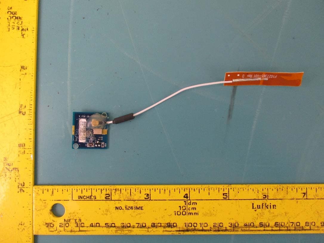
I28-EYSNSNZWWZ1
May 04, 2021BT5 Radio Module
Equipment Class
DTS - Digital Transmission System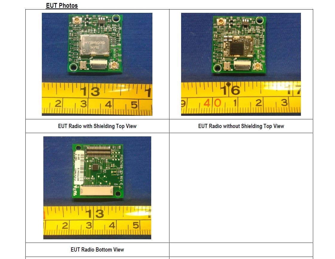
I28MD-FXLAN11AC
Nov 22, 2015Wireless 802.11ac + Bluetooth Module
Equipment Class
DSS - Part 15 Spread Spectrum Transmitter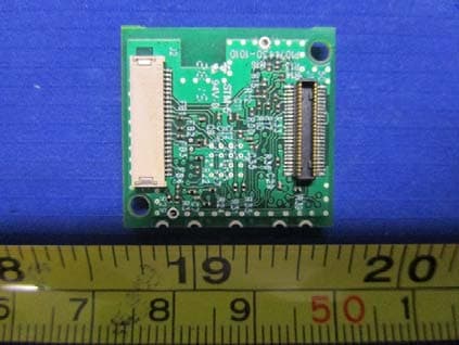
I28MD-ZBRBLE
Nov 19, 2015Bluetooth Low Energy Module
Equipment Class
DTS - Digital Transmission System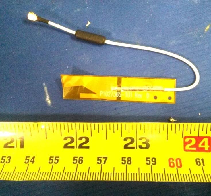
I28MD-ZBR7BTLE
Jan 19, 2015Bluetooth 4.0 LE Module
Equipment Class
DSS - Part 15 Spread Spectrum Transmitter