I28-R2844ZThermal Printer with RFID
Zebra Technologies Corporation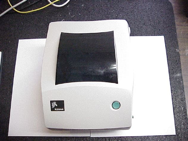
Click to zoom
Application Details
- Equipment Class
- DXX - Part 15 Low Power Communication Device Transmitter
- Date of Grant
- Apr 19, 2004
- Application Purpose
- Original Equipment
- Date of Application
- Apr 19, 2004
- Equipment Note
- Thermal Printer with RFID
- Frequency Range
- 13.56000000 - 13.56000000
- Country
- United States
Documents & Files
Document Text
Text extracted from the exhibit documents filed with the FCC. Open a document above to read the original.
Users Manual
Part #980476-001 | Rev. A User Guide Zebra ® TM Smart Label Printer and Encoder R2844-Z ii980476-001A Proprietary Statement This manual contains proprietary information of the manufacturer. It is intended solely for the information and use of parties operating and maintaining the equipment described herein. Such proprietary information may not be used, reproduced, or disclosed to any other parties for any other purpose without the expressed written permission of the manufacturer. Product Improvements Continuous improvement of products is a policy of the manufacturer. All specifications and signs are subject to change without notice. FCC Compliance Statement NOTE:This equipment has been tested and found to comply with the limits for a Class B digital device, pursuant to Part 15 of the FCC Rules. These limits are designed to provide reasonable protection against harmful interference in a residential installation. This equipment generates, uses, and can radiate radio frequency energy and, if not installed and used in accordance with the instructions, may cause harmful interference to radio communications. However, there is no guarantee that the interference will not occur in a particular installation. If this equipment does cause harmful interference to radio or television reception, which can be determined by turning the equipment off and on, the user is encouraged to try to correct the interference by one or more of the following measures: ■ Reorient or relocate the receiving antenna. ■ Increase the separation between the equipment and the receiver. ■ Connect the equipment into an outlet on a circuit different than that to which the receiver is connected. ■ Consult the dealer or an experienced Radio/TV technician for help. NOTE:This unit was tested with shielded cables on the peripheral devices. Shielded cables must be used with the unit to insure compliance. “The user is cautioned that any changes or modifications not expressly approved by the manufacturer could void the user’s authority to operate the equipment.” Industry Canada Statement IC: I28-R2844Z Operation is subject to the following two conditions: (1) this device may not cause interference, and (2) this device must accept any interference, including interference that may cause undesired operation of the device. Liability Disclaimer The manufacturer takes steps to assure that its published Engineering specifications and Manuals are correct; however, errors do occur. The manufacturer reserves the right to correct any such errors and disclaims liability resulting therefrom. No Liability for Consequential Damage In no event shall the manufacturer or anyone else involved in the creation, production, or delivery of the accompanying product (including hardware and software) be liable for any damages whatsoever (including, without limitation, damages for loss of business profits, business interruption, loss of business information, or other pecuniary loss) arising out of the use of or the results of use of or inability to use such product, even if the manufacturer has been advised of the possibility of such damages. Because some states do not allow the exclusion or limitation of liability for consequential or incidental damages, the above limitation may not apply to you. Trademarks and Copyrights The Zebra logo and the zebra head design are both registered trademarks and R2844-Z is a service mark of ZIH Corp. Windows and MS-DOS are registered trademarks of Microsoft Corp. Software® Zebra Technologies Corporation; all rights reserved worldwide. CG Triumvirate is a tradmark of AGFA Monotype Corporation; all rights reserved worldwide. CG Triumvirate™ Font© AGFA Monotype Corporation. Intellifont™ Portion© AGFA Monotype Corporation; all rights reserved worldwide. UFST is a registered tradmark of AGFA Monotype Corporation; all rights reserved worldwide. This product incorporates the ZPL®, ZPL II®, and Zebralink™ programs. This product incorporates the Element Energy Equalizer® circuit, and E3® circuit. All other marks are trademarks or registered trademarks of their respective holders. This copyrighted manual and the label printer described herein are owned by the manufacturer. All rights are reserved. Unauthorized reproduction of this manual or the software in the label printer may result in imprisonment of up to one year and fines of up to $10,000 (17 U.S.C.506). Copyright violators may be subject to civil liability. ©2004 ZIH Corp. All rights reserved. 980476-001Aiii Battery The main printed circuit board assembly includes a three-volt lithium battery. CAUTION •Risk of explosion if battery is replaced with an incorrect type. Note •Recycle batteries according to local your guidelines and regulations. Shock Hazard The printer and power supply should never be operated in a location where either one can get wet. Personal injury could result. Media and Ribbon Always use high-quality, approved labels, tags and ribbons. If adhesive backed labels are used that DO NOT lay flat on the backing liner, the exposed edges may stick to the label guides and rollers inside the printer, causing the label to peel off from the liner and jam the printer. Permanent damage to the print head may result if a non-approved ribbon is used as it may be wound incorrectly for the printer or contain chemicals corrosive to the print head. Approved supplies can be ordered from your dealer. If labels or ribbon run out while printing, DO NOT turn the power switch OFF (0) while reloading or data loss may result. After loading new supplies, press the feed button to resume printing. Static Discharge The discharge of electrostatic energy that accumulates on the surface of the human body or other surfaces can damage or destroy the print head or electronic components used in this device. DO NOT TOUCH the print head or the electronic components under the top cover. Thermal Printing The print head becomes hot while printing. To protect from damaging the print head and risk of person…
Text truncated - open the document above for the full version.
Users Manual
Getting Started This section describes how to set up your printer for the first time and use the most common operating procedures for loading media in tear-off mode and loading ribbon. Modes of Printing You can operate this printer in different modes: ■ Standard tear-off mode allows you to tear off each label (or a strip of labels) after it is printed. ■ In optional peel-off mode, the backing material is peeled away from the label as it is printed. After this label is removed, the next one is printed. ■ In optional cutter mode, an attached unit cuts through the media. The printer typically uses roll media, but you can use fan-fold or other continuous media as well. For procedures to use optional modes and features, refer to the Operation and Options section. 980476-001A7 Attaching Power Supply Check the power supply to make certain it is appropriate for your input voltage. Caution •Use the power supply that came with your printer. Never operate the printer and power supply in an area where they can get wet. Serious personal injury could result! 1. Make sure the power switch is in the off position (down). 2. The DC power supply has a barrel connector on one end that must be inserted into the power supply receptacle on the back of the printer. 3. Insert the separate AC power cord into the power supply. 4. Plug the other end of the cord into an appropriate AC electrical outlet. 8980476-001A Plug Varies b y Country AC Power Cord Power Supply Power Switch Power Supply Receptacle Barrel Connector Loading Roll Media When you load media, you must place the roll on the media hangers and then adjust the media guides. You must use the correct media for the type of printing you require. When printing without a ribbon, you must use direct thermal media. When using ribbon, you must use thermal transfer media. The printer's ribbon sensor detects motion of the supply spindle. Placing the Roll in the Media Compartment Whether your roll media is inside or outside wound you load it into the printer the same way. 1. Open the printer. Remember that you need to pull the release levers toward the front of the printer. 2. Remove the outside length of media. During shipment, the roll may become dirty when handled or dusty when stored. Removing the outside length avoids dragging adhesive or dirty media between the print head and platen. 3. Separate and hold open the media hangers. 4. Orient the media roll so that its printing surface will be up as it passes over the platen. 5. Lower the roll between the hangers and close them onto the core. 980476-001A9 MOVIE MOVIE Adjusting the Guides The adjustable guides direct the media toward the platen and print head. 1. Open the media guides by turning the guide adjuster knob to the rear. 2. Thread the media through the guides. 3. Close the media guides by turning the guide adjuster knob to the front. They should just touch, but not restrict, the edges of the media. 4. Unless you need to load ribbon, close the top cover. Remember that you need to release the cover lock, lower the top cover, and press down until the latches snap into place. 10980476-001A Using the Optional Media Adapter Plates If your media roll has a larger diameter core, you can use an accessory to adapt the core to the media holders. 1. Note which position will fit the diameter of the roll core. 2. On the left side plate, align the pegs with the screws and use a small Phillips driver to tighten them. 3. On the right side plate, align the pegs with the screws and use a small Phillips driver to tighten them. 4. Align the plates so that the pegs hold the roll core and press together. 5. Place the roll into the media compartment. 980476-001A11 Loading Ribbon You must use thermal transfer media (accepts wax and/or resin transferred off a ribbon) when you use a ribbon. When loading ribbon, you install the supply and take-up rolls, then tighten the ribbon on the carriage. Install the Ribbon Supply Roll Before following these steps, prepare the ribbon by removing its wrapping and pulling its adhesive strip free. 1. Thread the ribbon through the carriage. 2. Press the right side onto the supply hub. 3. Align the notches on the left side and mount onto the spokes of the left hub. Install the Take-Up Core 1. Press the right side onto the take-up hub. 2. Align the notches on the left side and mount onto the spokes of the left hub. You can find your first ribbon take-up core in the packing box. Subsequently, use the empty supply core to take up the next roll of ribbon. 12980476-001A MOVIE Attach and Tighten the Ribbon You must align the ribbon so that it will be taken straight onto the core. 1. Attach the ribbon to the take up core. Use the adhesive strip on new rolls; otherwise, use tape. 2. Turn the ribbon take-up gear counter-clockwise (top moves toward rear) to remove slack from the ribbon. 3. Close the top cover. Remember that you need to release the cover lock, lower the top cover, and press down until the latches snap into place. 980476-001A13 Operator Controls Power Switch Pressupto turnONordownto turnOFFthe printer. CAUTION •The power should be turned off before connecting or disconnecting the communications and power cables. Feed Button Press once to feed one blank label. Press once to take the printer out of a “pause” condition. (The printer is put into “pause” by either a programming command or an error condition.) See “What the Status Light is Telling You” on page 61. Use the Feed button for printer setup and status (see “Feed Button Modes” on page 70). Status Light Functions as a printer operational indicator (see “What the Status Light is Telling You” on page 61). 14980476-001A Printing a Test Label Before you connect the printer to your computer, make sure that the printer is in proper working order. You can do this by printing a configuration label. 1. Make sure the media is properly loaded and the top cover of the printer is closed. Then, turn the printer power on if you have not already done so. 2.…
Text truncated - open the document above for the full version.
Users Manual
Operation & Options This section helps you get the most from your printer. You must use programming to control many of the printer’s functions. A few examples: ■ The~JLcommand controls label length. ■ The^XA^MTD^XZcommand changes the printing mode to direct thermal; the ^XA^MTT^XZcommand changes the printing mode to thermal transfer. ■ The^XA^JUS^XZcommand saves the new settings to flash memory. For detailed information about creating labels using ZPL II, refer to theZPL II Programming Guideor visit our web site at www.zebra.com. To improve print quality, changing both print speed and density may be required to achieve the desired results. Your application’s printer driver provides control of the speed and heat (density). Thermal Printing The print head becomes hot while printing. To protect from damaging the print head and risk of personal injury, avoid touching the print head. Use only the cleaning pen to perform maintenance. The discharge of electrostatic energy that accumulates on the surface of the human body or other surfaces can damage or destroy the print head or electronic components used in this device. You must observe static-safe procedures when working with the print head or the electronic components under the top cover. You must use the correct media for the type of printing you require. When printing without a ribbon, you must use direct thermal media. When using ribbon, you must use thermal transfer media. The printer’s ribbon sensor detects motion of the supply spindle. 980476-001A21 Replacing Supplies If labels or ribbon run out while printing, leave the printer power on while reloading (data loss results if you turn off the printer). After you load a new label or ribbon roll, press the Feed button to restart . Always use high quality, approved labels, tags and ribbons. If adhesive backed labels are used that don’t lay flat on the backing liner, the exposed edges may stick to the label guides and rollers inside the printer, causing the label to peel off from the liner and jam the printer. Permanent damage to the print head may result if a non-approved ribbon is used as it may be wound incorrectly for the printer or contain chemicals corrosive to the print head. Approved supplies can be ordered from your dealer. Adding a New Transfer Ribbon If ribbon runs out in the middle of a print job, the indicator lights red and the printer waits for you to add a fresh roll. 1. Keep the power on as you change ribbon. 2. Open the top cover, then cut the used ribbon so you can remove the cores. 3. Load a new ribbon roll. If necessary, review the Ribbon Loading steps. 4. Close the top cover. 5. Press the Feed button to restart printing. Replacing a Partially Used Transfer Ribbon To remove used transfer ribbon, perform the following steps. 1. Cut the ribbon from the take-up roll. 2. Remove the take-up roll and discard used ribbon. 3. Remove the supply roll and tape the end of any fresh ribbon to prevent it from unwrapping. When reinstalling a partially used supply roll, tape the cut end onto the empty take-up roll. 22980476-001A Printing in Peel-Mode The optional dispenser allows you to print in “peel-mode” where the label backing follows a different path and the labels are presented one at a time for subsequent placement. Before using peel-mode, you must send the programming commands ^XA ^MMP ^XZ ^XA ^JUS ^XZ to the printer. Refer to yourZPL II Programmer’s Manual. 1. Remove several labels from the backing material. 2. Open the top cover. 3. Open the dispenser door. 4. Switch on the label-taken sensor. 5. Insert the backing in front of the peel bar and behind the peel roller. 6. Close the dispenser door. 7. Close the top cover. 8. Press the Feed button to advance the label. During the print job, the printer will peel off the backing and present a single label. Take the label from the printer so it will print the next label. 980476-001A23 ONOFF MOVIE Printing on Fan-Fold Media Printing on fan-fold media requires you to set both the media hangers and the media guides in position. 1. Open the top cover. 2. With a sample of your media, adjust the media hangers to the width of the media. The hangers should just touch, but not restrict, the edges of the media. 3. Tighten the screw using a small Phillips driver #1. 4. With a sample of your media, adjust the guides to the width of the media. The guides should just touch, but not restrict, the edges of the media. 5. Insert the media through the slot at the rear of the printer. 6. Run the media between the hangers and guides. 7. Close the top cover. 24980476-001A Lock-down Screw RFID Guidelines The Zebra R2844-Z Smart Label Printer and Encoder serves as dynamic tool for both printing and programming smart labels and tags. These labels and tags are usually made from two components, media and an RFID (radio frequency identification) transponder. ■ The media is comprised of synthetic- or paper-based material that can be printed upon using direct thermal or thermal transfer printing techniques. The media is typically made from the same materials and adhesives used by a standard barcode printer. ■ The transponder is usually comprised of an antenna coil that is bonded to an integrated circuit (IC) chip. The IC contains the drivers, coders, decoders and memory. At a minimum, the transponder has memory that can be read, while the vast majority also have memory that can be programmed by the user as well. 980476-001A25 Media Supply Media Transponder Outline of transponder ( shape varies by manufacturer ) Liner Media Transponder The communication between the RFID tag and the printer is established when the transponder lines up with the printer’s antenna. Note• The transponder position, prior to encode/decode, is critical. The optimal transponder position varies with antenna coil size and type of RFID IC used. It is important to use media and tags that have been specifically designed for use in this printer. Failure to do so may result in the inability to r…
Text truncated - open the document above for the full version.
Users Manual
52980476-001A Maintenance Cleaning When you clean the printer, use one or more of the following supplies that best suits your needs: CLEANING SUPPLIES Cleaning pens (12) Cleaning swabs (25) Cleaning cards, 4-in wide (25) Save-a-Print Head film, 4-in wide (3) The cleaning process takes just a couple of minutes using the steps outlined below. Printer PartMethodInterval Print head Let the print head to cool for one minute, then use a new cleaning pen to swab the print elements (the thin gray line on the print head) from end to end.NOTE:You do not have to turn off the printer to do this. If print quality remains poor after cleaning, try the Save-a-Print Head cleaning film to remove buildup without damaging the print head. Call your authorized reseller for more information. As necessary or after every five rolls of media Platen roller Manually rotate the platen roller. Clean it thoroughly with 70% isopropyl alcohol and a cleaning swab, cleaning card, or lint-free cloth. Peel bar Clean it thoroughly with 70% isopropyl alcohol and a cotton swab. As needed Tear bar ExteriorWater-dampened cloth InteriorBrush or air blow CutterUse tweezers to remove scraps 980476-001A53 Adhesives and coatings of media can over time transfer onto the printer components along the media path including the platen and print head. This build-up can accumulate dust and debris. Failure to clean the print head, media path and platen roller could result in inadvertent loss of labels, label jams and possible damage to the printer. Print Head Considerations Always use a new cleaning pen on the print head (an old pen carries contaminants from its previous uses that may damage the print head). Media Path Considerations Use a cleaning swab or pen to remove debris, dust or crust that has built-up on the holders, guides and media path surfaces. 1. Use the alcohol in the cleaning swab or pen to soak the debris so that it breaks up. 2. Wipe the area with the cleaning swab or pen to remove the debris. 3. Discard the cleaning swab or pen after use. Cleaning Card Considerations Use a cleaning card to remove debris that has built-up on the platen. Avoid scrubbing or vigorously rubbing the platen; otherwise, the surface could be damaged. 1. Open the printer and remove labels. 2. Place the cleaning card into the label path so that it is under the guides and it extends between the print head and platen roller. 3. Close and latch the printer. 4. With the power switch on, press the feed switch to move the cleaning card through the printer. 5. Discard the card after use. 54980476-001A MOVIE Platen Considerations The standard platen (drive roller) normally does not require cleaning. Paper and liner dust can accumulate without effecting print operations. Contaminates on the platen roller can damage the print head or cause the media to slip when printing. Adhesive, dirt, general dust, oils and other contaminates should be cleaned immediately off the platen. Keep a new platen available as a spare and install it whenever the printer has significantly poorer performance, print quality or media handling. If sticking or jamming continues even after cleaning, you must replace the platen. The platen can be cleaned with a fiber-free swab (such as a Texpad swab) or a lint free, clean, damp cloth very lightly moistened with medical grade alcohol (70% pure or better). 1. Open the media door and remove the media. 2. Clean the platen surface with the alcohol moistened swab. Rotate the platen while swabbing. Repeat this process two to three times with a new swab to remove residual contaminates. Adhesives and oils, for example, may be thinned by the initial cleaning but not completely removed. 3. Discard the cleaning swab or pen after use. Allow the printer to dry for one minute before loading labels. Lubrication No lubricating agents of any kind should be used on this printer! Some commercially available lubricants, if used, will damage the finish and the mechanical parts inside the printer. 980476-001A55 Replacing the Platen Removal Open the printer and remove any media. 1. Using a pointed stylus (such as tweezers, small slot-head screwdriver, or razor-knife), unhook the tabs on the right and left sides. Then rotate them forward. 2. Lift the platen out of the printer’s bottom frame. Assembly Make sure the right bearing is on the shaft of the platen. 1. Align the platen with the gear to the left and lower it into the printer’s bottom frame. 2. Rotate the tabs back and snap them into place. 56980476-001A MOVIE Replacing the Print Head In the event you need to replace the print head, read the procedure and review the removal and installation steps before actually replacing the print head. Prepare your work area by protecting against static discharge. Your work area must be static-safe and include a properly grounded conductive cushioned mat to hold the printer and a conductive wrist strap for yourself. CAUTION •Turn the printer power off and unplug the power cord before replacing the print head. 980476-001A57 MOVIE Thermal-Transfer TLP Model Before following the steps in this procedure, open the printer by pulling the release latches forward then lifting the top cover. Remove any ribbon from the carriage. Removal 1. Grasp the print head spring and pull it to the left; then, slide it free of the carriage. 2. Use the spring to pry the print head clip off the right side of the carriage. 3. Pull the print head and bracket forward. 4. Use a #2 Phillips driver to remove the screw that holds the ground wire. 5. Unplug both bundles of print head wires from their connectors. 58980476-001A MOVIE Replacing the TLP Print Head (Continued) Assembly The new print head comes with the clip and ground screw attached. 1. Align the print head and bracket to plug the left and right connectors into the black and white wire bundles. 2. Attach the ground wire and secure it with the screw. Use a #2 Phillips driver to tighten it. 3. Insert the bracket pegs into the left side of the carr…
Text truncated - open the document above for the full version.
Cover Letter(s)
1 scott To: [email protected] Subject: FCC ID: I28-R2844Z Mr. Madlangbayan: In order for processing of this application (FCC ID: I28-R2844Z) to continue, the following issue(s) will have to be addressed: 1) The test report data sheets for frequencies between 10 kHz to 30 MHz indicates that the loop antenna was used in two polarizations. The loop antenna is required to be rotated about its vertical and horizontal axis in order to maximize an emission. Please provide data using this procedure. FYI: While it is not a compliance issue in this case (since the peak of the fundamental emission of the transmitter meets the spurious emission limits contained in 15.209), please, in the future, provide plots showing band edge compliance on future submissions. FYI: The limit specified for the fundamental emission in the test report is incorrect. This rule section was recently modified under Report and Order FCC 03-149. The new limits came into effect on January 8th of this year. Since the limits were increased, it is not a compliance issue, and no further action is necessary. The item(s) indicated above must be submitted before processing can continue on the above referenced application. Failure to provide the requested information within 60 days of the original e-mail date may result in application dismissal and forfeiture of the filing fee. Also, please note that partial responses increase processing time and should not be submitted. Please submit your response(s) as correspondence on our electronic filing website, using correspondence number: I28-R2844Z-1 Any questions about the content of this correspondence should be directed to [email protected]. If you have any questions, feel free to contact me. Best Regards, Scott McCutchan Operations Manager Compatible Electronics TCB 114 Olinda Drive Brea, California 92823 Main (714) 579-0500 Direct (714) 579-1489 Fax (714) 579-1850 [email protected] www.celectronics.com Correspondence by Project Project Number: -1120643159 Correspondence Number Memo I28-R2844Z-1 Mr. Scott McCutchen, I am sending a Revised Test report which addresses the issues discussed earlier. I am also sending a copy of a letter requesting the Schematics, Block Diagrams and Operational description be held Confidential. If You have any questions please feel free to contact me. Thank You. Mr. Joey Madlangbayan Test Engineer Compatible Electronics
ID Label/Location Info
Zebra Technologies Corporation 1001 Flynn Road Camarillo, CA 93012-8706 Telephone: (+1)805.579.1800 FAX: (+1)805.579.1808 www.Zebra.com March 18, 2004 R2844-Z Agency Label. Note: Use only UL approved ink, Sony 4070 or Ricoh B110C. Label made from Flexcon 22830, silver 2.125 X 3 inches
Test Report
FCC ID: I28-R2844Z Report Number: A40219F1 2337 TROUTDALE DRIVE, AGOURA, CALIFORNIA, 91301 • PH: (818) 597-0600 FX: (818) 597-1187 Page 1 of 19 FCC PART 15, SUBPART C TEST REPORT for THERMAL PRINTER with RFID Model: R2844-Z FCC ID: I28-R2844Z Prepared for ZEBRA TECHNOLOGIES CORP. 1001 FLYNN RD CAMARILLO, CA 93012 Prepared by: _____________________ JOEY J. MADLANGBAYAN Approved by: ____________________ RUBY A. HALL COMPATIBLE ELECTRONICS INC. 2337 TROUTDALE DRIVE AGOURA, CALIFORNIA 91301 (818) 597-0600 DATE: APRIL 1, 2004 REPORT APPENDICES TOTAL BODY A B C D E PAGES 19 2 2 2 12 12 49 This report shall not be reproduced except in full, without the written approval of Compatible Electronics. FCC ID: I28-R2844Z Report Number: A40219F1 2337 TROUTDALE DRIVE, AGOURA, CALIFORNIA, 91301 • PH: (818) 597-0600 FX: (818) 597-1187 Page 2 of 19 TABLE OF CONTENTS Section / Title PAGE GENERAL REPORT SUMMARY 4 SUMMARY OF TEST RESULTS 4 1. PURPOSE 5 2. ADMINISTRATIVE DATA 6 2.1 Location of Testing 6 2.2 Traceability Statement 6 2.3 Cognizant Personnel 6 2.4 Date Test Sample was Received 6 2.5 Disposition of the Test Sample 6 2.6 Abbreviations and Acronyms 6 3. APPLICABLE DOCUMENTS 7 4. Description of Test Configuration 8 4.1 Description of Test Configuration - EMI 8 4.1.1 Photograph of Test Configuration – EMI 8 4.1.2 Cable Construction and Termination 9 5. LISTS OF EUT, ACCESSORIES AND TEST EQUIPMENT 10 5.1 EUT and Accessory List 10 5.2 EMI Test Equipment 11 6. TEST SITE DESCRIPTION 13 6.1 Test Facility Description 13 6.2 EUT Mounting, Bonding and Grounding 13 7. Test Procedures 14 7.1 RF Emissions 14 7.1.1 Conducted Emissions Test 14 7.1.2 Radiated Emissions Test 15 7.1.3 Radiated Emissions – Frequency Tolerance 16 7.1.4 Radiated Emissions - Test Results 17 7.1.5 Sample Calculations 18 8. CONCLUSIONS 19 FCC ID: I28-R2844Z Report Number: A40219F1 2337 TROUTDALE DRIVE, AGOURA, CALIFORNIA, 91301 • PH: (818) 597-0600 FX: (818) 597-1187 Page 3 of 19 LIST OF APPENDICES APPENDIX TITLE A Laboratory Accreditations B Modifications to the EUT C Additional Models Covered Under This Report D Diagrams, Charts and Photos • Test Setup Diagrams • Antenna and Amplifier Gain Factors • Radiated and Conducted Emissions Photos E Data Sheets LIST OF FIGURES FIGURE TITLE 1 Conducted Test Setup 2 Plot Map And Layout of Test Site FCC ID: I28-R2844Z Report Number: A40219F1 2337 TROUTDALE DRIVE, AGOURA, CALIFORNIA, 91301 • PH: (818) 597-0600 FX: (818) 597-1187 Page 4 of 19 GENERAL REPORT SUMMARY This electromagnetic emission report is generated by Compatible Electronics Inc., which is an independent testing and consulting firm. The test report is based on testing performed by Compatible Electronics personnel according to the measurement procedures described in the test specifications given below and in the "Test Procedures" section of this report. The measurement data and conclusions appearing herein relate only to the sample tested and this report may not be reproduced in any form except in full, without the written permission of Compatible Electronics. This report must not be used to claim product endorsement by NVLAP or any other agency of the U.S. Government. Device Tested: Thermal Printer with RFID Model: R2844-Z S/N: None Product Description: This is a 4” wide, 200 dpi Thermal Printer with …
Text truncated - open the document above for the full version.
Contact Information
Applicant
Jay Cadiz(Sr. Manager, Regulatory)
Technical Contact
Compatible ElectronicsJoey Madlangbayan
[email protected]818-597-0600
2337 Troutdale Drive · Agoura, California · United States
Test Firm
Compatible Electronics, Inc.Jeff Klinger
Technical Specifications
| # | Rule Parts | Frequency Range | Power Output |
|---|---|---|---|
| 1 | 15C | 13.56 MHz - 13.56 MHz | - |
Other Applications from Zebra Technologies Corporation
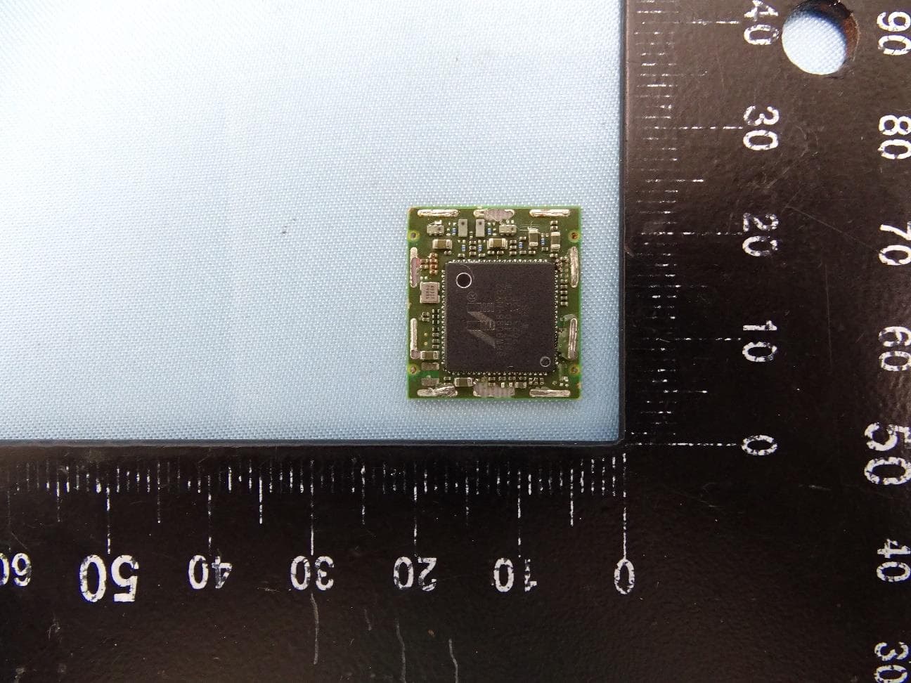
I28-WYSBHVDXP
May 19, 2021WLAN/BTLE module
Equipment Class
DTS - Digital Transmission System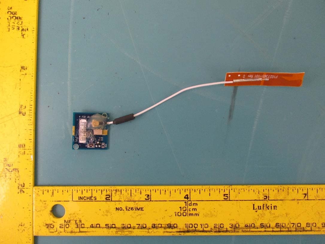
I28-EYSNSNZWWZ1
May 04, 2021BT5 Radio Module
Equipment Class
DTS - Digital Transmission System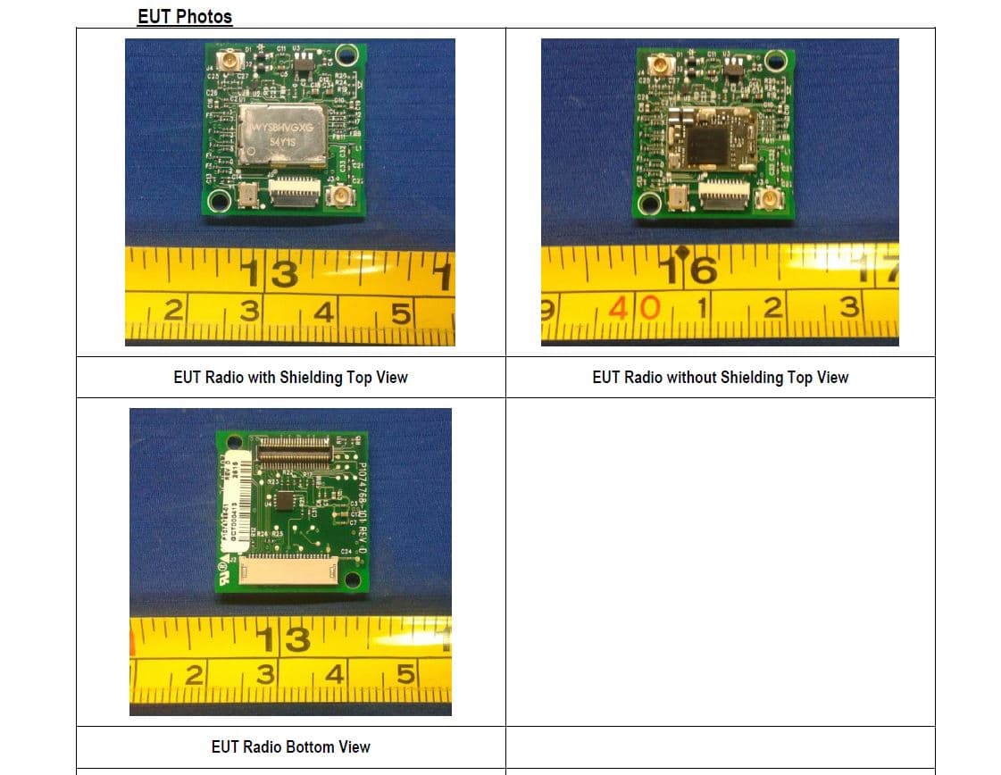
I28MD-FXLAN11AC
Nov 22, 2015Wireless 802.11ac + Bluetooth Module
Equipment Class
DSS - Part 15 Spread Spectrum Transmitter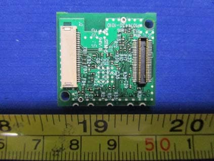
I28MD-ZBRBLE
Nov 19, 2015Bluetooth Low Energy Module
Equipment Class
DTS - Digital Transmission System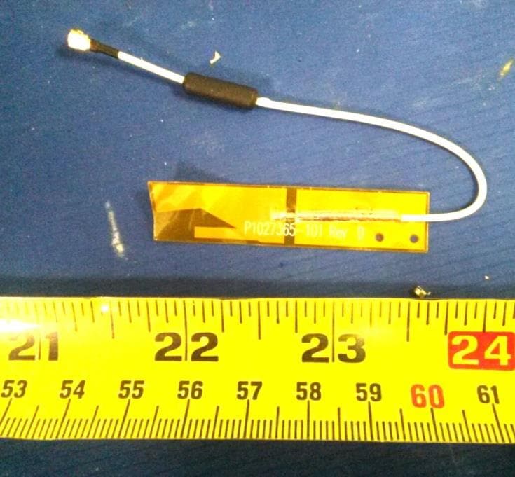
I28MD-ZBR7BTLE
Jan 19, 2015Bluetooth 4.0 LE Module
Equipment Class
DSS - Part 15 Spread Spectrum Transmitter