I28MD-BTC2TY2ZBR3 Modular Bluetooth Radio
Zebra Technologies Corporation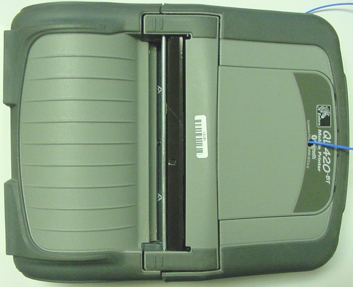
Click to zoom
Application Details
- Equipment Class
- DSS - Part 15 Spread Spectrum Transmitter
- Date of Grant
- Dec 10, 2004
- Application Purpose
- Original Equipment
- Date of Application
- Dec 10, 2004
- Equipment Note
- ZBR3 Modular Bluetooth Radio
- Frequency Range
- 2402.00000000 - 2480.00000000
- Country
- United States
Documents & Files
Document Text
Text extracted from the exhibit documents filed with the FCC. Open a document above to read the original.
Users Manual
Rhein Tech Laboratories Client: Zebra Technologies Corp. 360 Herndon Parkway Model Name/#: ZBR-3/EYSF2CAXX Suite 1400 FCC ID: I28MD-BTC2TY2 FCC: 15.247 Herndon, VA 20170 http://www.rheintech.com IC: RSS-210 Page 82 of 82 APPENDIX J: MANUAL Please refer to the following pages for a representative manual of a Zebra product that could contain the Zebra Model ZBR-3. User Guide QL Series UMAN-QL rev. A February 2004 3 QL Series User Guide Table of Contents Proprietary Statement................................................. 5 Introduction to the QL Series ..................................... 7 Unpacking and Inspection.......................................................................... 7 Reporting Damage...................................................................................... 7 QL 220 Introduction.................................................................................... 8 QL 320 Introduction.................................................................................... 9 QL 420 Introduction.................................................................................. 10 Getting Ready to Print ................................................ 11 Battery.......................................................................... 11 Installing the Battery .................................................................................. 11 Charging the Battery .................................................................................. 12 LI 72 Single Battery Charger..................................................................... 12 UCLI72-4 Quad Charger............................................................................ 13 Battery Safety ............................................................................................. 14 Charger Safety ........................................................................................... 15 Loading the Media..................................................... 16 Installing the Media ................................................................................... 16 Operator Controls...................................................... 21 Standard Keypad ....................................................................................... 21 LCD Control Panel ...................................................................................... 23 Verify the Printer Is Working ..................................... 26 Printing a Configuration Label ................................................................... 26 Connecting the Printer.............................................. 26 Cable Communications ............................................................................. 27 IR Communications ................................................................................... 28 Wireless Communications with Bluetooth™using ZBR-2 Radio .............. 29 Wireless Local Area Network (WLAN) Module Using CF Radio .............. 31 QL 320 Wireless Local Area Network (WLAN) Module Using PCMCIA Radio .......................................................................................................... 33 QL 420 Wireless Local Area Network (WLAN) Module Using PCMCIA Radio .......................................................................................................... 35 Frequency Hopping Wireless Local Area Network (WLAN) Module Using PCMCIA Radio ............................................................................................ 37 WLAN Overview........................................................................................ 39 Setting Up the Software............................................ 39 Using the Accessories............................................... 41 Belt Clip...................................................................................................... 41 Kickstand .................................................................................................... 41 Desk Stand ................................................................................................. 42 Adjustable Shoulder Strap ........................................................................ 43 Carrying Strap ............................................................................................ 44 Preventive Maintenance............................................ 45 Extending Battery Life............................................................................... 45 Cleaning Instructions................................................................................ 45 QL220 Cleaning .......................................................................................... 47 QL 320 Cleaning ......................................................................................... 49 QL 420 Cleaning ......................................................................................... 51 Troubleshooting......................................................... 52 Standard Control Panel............................................................................. 52 Optional LCD Control Panel...................................................................... 52 Troubleshooting Topics............................................................................ 53 Troubleshooting Tests............................................................................... 55 Printing a Configuration Label ................................................................... 55 Communications Diagnostics ................................................................... 55 Calling Technical Support .......................................................................... 58 Specifications............................................................. 59 Printing Specifications ............................................................................... 59 Memory/Communications Specifications ................................................ 59 …
Text truncated - open the document above for the full version.
Cover Letter(s)
American Telecommunications Certification Body Inc. 6731 Whittier Ave, McLean, VA 22101 November 24, 2004 RE: Zebra Technologies FCC ID: I28MD-BTC2TY2 I have a few comments on the above referenced Application. General Issues: 1) In the antenna gain information file, the extra attenuation shown in the calculations does not appear to match the table for both the QL family antennas. Please correct as appropriate. 2) This application appears to cover 9 configurations. However only 2 labels appear to be provided. Both sample labels appear to be for the external portion of the final devices and not the module itself. However one label uses the word “contains” while the other does not. Please explain/justify this. Additionally, the first label does not include information regarding the FCC 2 part statement or DoC information. Please explain/correct as necessary. 3) It appears that an excessive length of cable was used between the module and antenna compared to the length that will normally be installed. The FCC desires the shortest cable expected to be used. Will all devices utilize this length cable. If not, how was the effect of the excess cable factored into the testing/results. 4) Page 6 of the test report appears to suggest testing was only done upto the 2 nd LO harmonic. Please explain as the FCC expects testing performed to 10 x the highest frequency generated or used. 5) Page 49 shows average measurements above 1 GHz. However, compliance must also be shown to the peak limits above 1 GHz. Please either provide peak measurements or an explanation of the peak to average ratio. 6) 5 out of 6 pages of the schematics do not show values/emissions designators. Please correct. 7) Spurious emissions must be tested for a low, mid, and high channel. Only middle channel results were provided. Please provide additional data. 8) Were spurious emission measured for both H and V polarities in order to obtain worse case results for each antenna? 9) The maximum dwell time measured was 8 ms in a 31.6 second period. Something does not appear correct regarding how the TX was behaving. Most Bluetooth tests show results just under the 400 msec requirement. Assuming a TX time of 419 us, this would mean the device would return to the same channel approximately every 66 msec assuming a full duplex TX. In a 31.6 sec period of time the same channel would be visited 477 times. Additionally, if the device was properly hopping through the hop table, the spacing between all TX cycles would be the same. This is not shown in plot 11-3 and therefore each channel does not appear to be used equally on the average as required by the rules. Lastly, the theory of operation mentions beacon intervals lasting 100 ms, which implies dwell times of 200 msec or longer. Note that the minimum hop cycle listed in the theory of operation is 2.5 hops per second or 400 msec dwell time maximum. Please provide more theory of dwell time information or data as necessary regarding this issue. Note that additionally, for systems with 20 dB bandwidth < 1 MHz, a 30 second measurement period is specified. 10) The 6 dB bandwidth is not applicable to this device and therefore this data should be removed from the report. 11) Something appears odd about he 20 dB bandwidth. I have never seen a Bluetooth with this narrow of a bandwidth. Most appear to have about an 800-900 kHz 20 dB bandwidth using a 10 or 30 kHz RBW. Is it possible the test software is not behaving properly? How does this affect other tests? Please review and verify as necessary. 12) The users manual should include prohibition against co-location such as: “The antenna(s) used for this transmitter must not be co-located or must not operate in conjunction with any other antenna.” 13) It is suggested to provide an RF exposure exhibit similar to the example attached as appropriate for this device. --- Continued on Next Page --- z Page 2 November 24, 2004 14) FYI.....Proposed Grant Notes: Limited Modular Approval (LMA). Approval is limited to installation only within Zebra Technologies Corporation devices using antennas specified in this filing. Power output listed is conducted. The WLAN device and antenna must be installed and properly labeled by the OEM. The antenna(s) used for this transmitter must not be co-located or must not operate in conjunction with any other antenna. End-users must be provided with specific operating instructions for satisfying RF exposure compliance. End users must not be provided with information on how to remove or install the device. Timothy R. Johnson Examining Engineer mailto: [email protected] The items indicated above must be submitted before processing can continue on the above referenced application. Failure to provide the requested information may result in application termination. Correspondence should be considered part of the permanent submission and may be viewed from the Internet after a Grant of Equipment Authorization is issued. Please do not respond to this correspondence using the email reply button. In order for your response to be processed expeditiously, you must submit your documents through the AmericanTCB.com website. Also, please note that partial responses increase processing time and should not be submitted. Any questions about the content of this correspondence should be directed to the sender.
Cover Letter(s)
American Telecommunications Certification Body Inc. 6731 Whittier Ave, McLean, VA 22101 November 24, 2004 RE: Zebra Technologies FCC ID: I28MD-BTC2TY2 I have a few comments on the above referenced Application. General Issues: 1) In the antenna gain information file, the extra attenuation shown in the calculations does not appear to match the table for both the QL family antennas. Please correct as appropriate. Response : Please see the revised antenna specification document uploaded with this response. Zebra corrected the second QL antenna calculation, but believes the first one is correct. The table at the end only relates to the test antennas that Zebra provided to Rhein Tech. Cable lengths used at Zebra for antenna patterns and gain were not necessarily the same as what is in the table, so the correction factors can be different. In many cases, the lengths were the same. The correction factors that Zebra used in the document correspond to the Zebra cable lengths used for the antenna gain testing. 2) This application appears to cover 9 configurations. However only 2 labels appear to be provided. Both sample labels appear to be for the external portion of the final devices and not the module itself. However one label uses the word “contains” while the other does not. Please explain/justify this. Additionally, the first label does not include information regarding the FCC 2 part statement or DoC information. Please explain/correct as necessary. Response : Please review the label samples again, as both samples do include the word “contains”, as do the labels for the other printers in which the EUT would be placed. Samples of the labels for the other printers can be provided if necessary. The EUT itself is only .5 x .5 inches, far too small to hold the FCC ID label. The FCC 2 part statement actually appears on a label on the outside of the device, as can be seen in the External Photo exhibits. 3) It appears that an excessive length of cable was used between the module and antenna compared to the length that will normally be installed. The FCC desires the shortest cable expected to be used. Will all devices utilize this length cable. If not, how was the effect of the excess cable factored into the testing/results. Response : Testing was performed with longer cables in order to test the antenna as they will be installed in the final host products. This cable length was necessary for testing purposes. Additionally, this length eliminated any influence of the antenna and housing to the module under test. Based on the low emissions data and the low loss of the cable (see antenna specification document) we feel that this test configuration was an appropriate compromise between cable length and the physical constraints of the test environment. 4) Page 6 of the test report appears to suggest testing was only done up to the 2 nd LO harmonic. Please explain as the FCC expects testing performed to 10 x the highest frequency generated or used. Response : Emissions were investigated up to 24 GHz. The 2 nd LO” language in the test report was not applicable to this device and has been removed. American Telecommunications Certification Body Inc. 6731 Whittier Ave, McLean, VA 22101 5) Page 49 shows average measurements above 1 GHz. However, compliance must also be shown to the peak limits above 1 GHz. Please either provide peak measurements or an explanation of the peak to average ratio. Response : Peak measurements are now included with average for compliance. Please see the revised test report uploaded with this response. 6) 5 out of 6 pages of the schematics do not show values/emissions designators. Please correct. Response : As agreed upon in an email on November 29, the schematic file uploaded on November 29 addresses this issue. 7) Spurious emissions must be tested for a low, mid, and high channel. Only middle channel results were provided. Please provide additional data. Response : Low and high channels are now included. Please see the revised test report. 8) Were spurious emission measured for both H and V polarities in order to obtain worse case results for each antenna? Response : Yes, spurious emissions were measured for both horizontal and vertical polarities. Worst case data is presented in the test report. 9) The maximum dwell time measured was 8 ms in a 31.6 second period. Something does not appear correct regarding how the TX was behaving. Most Bluetooth tests show results just under the 400 msec requirement. Assuming a TX time of 419 us, this would mean the device would return to the same channel approximately every 66 msec assuming a full duplex TX. In a 31.6 sec period of time the same channel would be visited 477 times. Additionally, if the device was properly hopping through the hop table, the spacing between all TX cycles would be the same. This is not shown in plot 11-3 and therefore each channel does not appear to be used equally on the average as required by the rules. Lastly, the theory of operation mentions beacon intervals lasting 100 ms, which implies dwell times of 200 msec or longer. Note that the minimum hop cycle listed in the theory of operation is 2.5 hops per second or 400 msec dwell time maximum. Please provide more theory of dwell time information or data as necessary regarding this issue. Note that additionally, for systems with 20 dB bandwidth < 1 MHz, a 30 second measurement period is specified. Response : The longest pulse noted in normal operation of this device while in active communication with an off-the-shelf device was 262 us, which is now included in the report. In normal communication mode, it is difficult to show the spacing due to the cross communication timing with the alternate device. If it could be shown, equal pulses of 262 us could be equivalent to 300 pulses in a 30 second period or a 78.6 ms average occupancy rate. It has been shown in the now included plots that 215 pulses for a 56.3 ms occupancy rate, both of which are well below the 400 ms limi…
Text truncated - open the document above for the full version.
Cover Letter(s)
Rhein Tech Laboratories Client: Zebra Technologies Corp. 360 Herndon Parkway Model Name/#: ZBR-3/EYSF2CAXX Suite 1400 FCC ID: I28MD-BTC2TY2 FCC: 15.247 Herndon, VA 20170 http://www.rheintech.com IC: RSS-210 Page 76 of 82 APPENDIX D: AGENCY AUTHORIZATION LETTER Please refer to the following page.
Cover Letter(s)
Rhein Tech Laboratories Client: Zebra Technologies Corp. 360 Herndon Parkway Model Name/#: ZBR-3/EYSF2CAXX Suite 1400 FCC ID: I28MD-BTC2TY2 FCC: 15.247 Herndon, VA 20170 http://www.rheintech.com IC: RSS-210 Page 77 of 82 APPENDIX E: CONFIDENTIALITY REQUEST LETTER Please refer to the following page. s s
Cover Letter(s)
Rhein Tech Laboratories Client: Zebra Technologies Corp. 360 Herndon Parkway Model Name/#: ZBR-3/EYSF2CAXX Suite 1400 FCC ID: I28MD-BTC2TY2 FCC: 15.247 Herndon, VA 20170 http://www.rheintech.com IC: RSS-210 Page 73 of 82 APPENDIX A: MODULAR APPROVAL JUSTIFICATION STATEMENT Please see the following page. 30 Plan Way Warwick, RI 02886 U.S.A. Telephone +1401.739.5800 / 800.556.7266 Facsimile +1.401.732.0145 www.zebra.com 10/07/2004 Federal Communications Commission 7435 Oakland Mills Road Columbia, MD 21046-1609 To Whom It May Concern: In reference to the application for FCC ID#: I28MD-BTC2TY2 (Zebra ZBR3 Bluetooth radio module), this device is being submitted for limited MODULAR TRANSMITTER APPROVAL based on the guidelines in FCC Publication DA 00-1407. We believe that this transmitter meets all 8 criterion listed in DA 00-1407 as detailed in the paragraphs below. Note that I28MD-BTC2TY2 is a radio module that will be used exclusively within products made by Zebra Technologies Corporation. 1) I28MD-BTC2TY2 is based on a Taiyo-Yuden EYSF2CAXX self-contained Bluetooth radio module. The EYSF2CAXX is fully shielded. 2) I28MD-BTC2TY2 has buffered inputs on all digital lines. Overdriving one or more of the digital inputs will have no affect on the transmitter output. 3) I28MD-BTC2TY2 contains a voltage regulator that powers the transmitter. The unit is designed to accept regulated 3.3 volts DC at it’s input, but transmitter output will not be affected if input voltage is exceeded. Since the module will only be used in Zebra products, Zebra has full control of the power supply to the module. 4) I28MD-BTC2TY2 will always be used with one of a family of approved antennas, all of which are mounted (with the radio) inside a finished printer or other product. None of these antennas is user accessible, nor is the antenna cable / connector user accessible; for this reason the antennas can be considered to be permanently attached. All of the antennas in the family have been tested with the radio module as part of the modular approval; test results are included with the application. If the radio is to be used with a new antenna, further testing will be performed and a Class II permissive change will be obtained. 5) I28MD-BTC2TY2 was tested in a stand-alone configuration, outside of any Zebra printer.
Cover Letter(s)
Re: FCC ID: I28MD-BTC2TY2 Applicant: Zebra Technologies Corporation Correspondence Reference Number: 21580 731 Confirmation Number: TC858124 Date of Original Email: 07/12/2005 Subject: audit FCC Comment: This grant is for P<1mW Bluetooth - please explain grant comment: "The WLAN device and antenna must be installed and properly labeled by the OEM." Response: There were concerns regarding the labeling aspect of the device. Namely that the label is placed on the cover or chassis of the device it is installed within, not on the TX module itself, therefore it does not fully follow the requirement 6 of the modular approval notice DA 001407. However, detailed discussions for this same manufacturer and same situation were previously performed on an earlier application for FCC ID: I28MD- QL3021, where this same problem existed as well. After all discussions, and a verbal conversation with Rich Fabina, the FCC did not have a problem with this as long as the 2 conditions below existed, one of them being that the grant of Certification is conditioned accordingly. Therefore the portion of the grant notes in question were based upon an earlier application by the same applicant under FCC ID: I28MD-QL3021, by which the same concerns regarding labeling were addressed. Copy of response from FCC regarding I28MD-QL3021 Tim, Based upon our review of the information attached to your email, we have no problem with the labeling scheme for the limited modular approval as proposed based upon the following conditions: (1) The OEM installs the module in these two printers and places the FCC ID label on the modified printers, and (2) The grant of Certification is conditioned accordingly. We have never allowed a consumer to place an FCC ID label on a product. However, the approval is for a limited modular approval and we believe that the OEM maintains sufficient control over the marketed product to make sure the it is properly installed and labeled. Therefore, we have no problems with the proposed labeling of the device as submitted. We also note that any other device into which this module will be installed must be approved as a Class II permissive change filing by either a TCB or the Commission. If you have any further questions about this matter, please contact me directly. Rich Fabina
External Photos
Rhein Tech Laboratories Client: Zebra Technologies Corp. 360 Herndon Parkway Model Name/#: ZBR-3/EYSF2CAXX Suite 1400 FCC ID: I28MD-BTC2TY2 FCC: 15.247 Herndon, VA 20170 http://www.rheintech.com IC: RSS-210 APPENDIX L: EXTERNAL PHOTOGRAPHS PHOTOGRAPH 20: TOP VIEW CAMEO 3 ANTENNA INSTALLED IN TYPICAL HOST Rhein Tech Laboratories Client: Zebra Technologies Corp. 360 Herndon Parkway Model Name/#: ZBR-3/EYSF2CAXX Suite 1400 FCC ID: I28MD-BTC2TY2 FCC: 15.247 Herndon, VA 20170 http://www.rheintech.com IC: RSS-210 PHOTOGRAPH 21: REAR VIEW CAMEO 3 ANTENNA INSTALLED IN TYPICAL HOST Rhein Tech Laboratories Client: Zebra Technologies Corp. 360 Herndon Parkway Model Name/#: ZBR-3/EYSF2CAXX Suite 1400 FCC ID: I28MD-BTC2TY2 FCC: 15.247 Herndon, VA 20170 http://www.rheintech.com IC: RSS-210 PHOTOGRAPH 22: TOP VIEW CAMEO 2 ANTENNA INSTALLED IN TYPICAL HOST Rhein Tech Laboratories Client: Zebra Technologies Corp. 360 Herndon Parkway Model Name/#: ZBR-3/EYSF2CAXX Suite 1400 FCC ID: I28MD-BTC2TY2 FCC: 15.247 Herndon, VA 20170 http://www.rheintech.com IC: RSS-210 PHOTOGRAPH 23: REAR VIEW CAMEO 2 ANTENNA INSTALLED IN TYPICAL HOST Rhein Tech Laboratories Client: Zebra Technologies Corp. 360 Herndon Parkway Model Name/#: ZBR-3/EYSF2CAXX Suite 1400 FCC ID: I28MD-BTC2TY2 FCC: 15.247 Herndon, VA 20170 http://www.rheintech.com IC: RSS-210 PHOTOGRAPH 24: FRONT VIEW QL-420 ANTENNA INSTALLED IN TYPICAL HOST Rhein Tech Laboratories Client: Zebra Technologies Corp. 360 Herndon Parkway Model Name/#: ZBR-3/EYSF2CAXX Suite 1400 FCC ID: I28MD-BTC2TY2 FCC: 15.247 Herndon, VA 20170 http://www.rheintech.com IC: RSS-210 PHOTOGRAPH 25: REAR VIEW QL-420 ANTENNA INSTALLED IN TYPICAL HOST
External Photos
Rhein Tech Laboratories Client: Zebra Technologies Corp. 360 Herndon Parkway Model Name/#: ZBR-3/EYSF2CAXX Suite 1400 FCC ID: I28MD-BTC2TY2 FCC: 15.247 Herndon, VA 20170 http://www.rheintech.com IC: RSS-210 PHOTOGRAPH 26: FRONT VIEW CAMEO 3 SC ANTENNA INSTALLED IN TYPICAL HOST Rhein Tech Laboratories Client: Zebra Technologies Corp. 360 Herndon Parkway Model Name/#: ZBR-3/EYSF2CAXX Suite 1400 FCC ID: I28MD-BTC2TY2 FCC: 15.247 Herndon, VA 20170 http://www.rheintech.com IC: RSS-210 PHOTOGRAPH 27: REAR VIEW CAMEO 3 SC ANTENNA INSTALLED IN TYPICAL HOST Rhein Tech Laboratories Client: Zebra Technologies Corp. 360 Herndon Parkway Model Name/#: ZBR-3/EYSF2CAXX Suite 1400 FCC ID: I28MD-BTC2TY2 FCC: 15.247 Herndon, VA 20170 http://www.rheintech.com IC: RSS-210 PHOTOGRAPH 28: FRONT VIEW QL FAMILY 2ND GENERATION ANTENNA INSTALLED IN TYPICAL HOST Rhein Tech Laboratories Client: Zebra Technologies Corp. 360 Herndon Parkway Model Name/#: ZBR-3/EYSF2CAXX Suite 1400 FCC ID: I28MD-BTC2TY2 FCC: 15.247 Herndon, VA 20170 http://www.rheintech.com IC: RSS-210 PHOTOGRAPH 29: REAR VIEW QL FAMILY 2 ND GENERATION ANTENNA INSTALLED IN TYPICAL HOST Rhein Tech Laboratories Client: Zebra Technologies Corp. 360 Herndon Parkway Model Name/#: ZBR-3/EYSF2CAXX Suite 1400 FCC ID: I28MD-BTC2TY2 FCC: 15.247 Herndon, VA 20170 http://www.rheintech.com IC: RSS-210 PHOTOGRAPH 30: FRONT VIEW ZPR POD ANTENNA INSTALLED IN TYPICAL HOST Rhein Tech Laboratories Client: Zebra Technologies Corp. 360 Herndon Parkway Model Name/#: ZBR-3/EYSF2CAXX Suite 1400 FCC ID: I28MD-BTC2TY2 FCC: 15.247 Herndon, VA 20170 http://www.rheintech.com IC: RSS-210 PHOTOGRAPH 31: REAR VIEW ZPR POD ANTENNA INSTALLED IN TYPICAL HOST
ID Label/Location Info
Rhein Tech Laboratories Client: Zebra Technologies Corp. 360 Herndon Parkway Model Name/#: ZBR-3/EYSF2CAXX Suite 1400 FCC ID: I28MD-BTC2TY2 FCC: 15.247 Herndon, VA 20170 http://www.rheintech.com IC: RSS-210 Page 79 of 82 APPENDIX G: LABEL AND LABEL LOCATION Please see the following pages for representative samples of the FCC and Industry Canada Identification Labels, and label locations, on some typical Zebra printers. E F F1 G H J D C B A Rev. ECO # 1 2 Description: Part Number: This drawing contains confidential and other data of a proprietary nature owned by Zebra Technologies Corporation. and may not be used or disclosed to others without the prior written consent of Zebra Technologies Corporation. DwnAppvd.Date. R 0.025" typ. [.64 mm] 3.170" [80.5 mm] 0.300" [7.6 mm] R 0.443" typ. [11.2 mm] R 4.110" [10.4 cm] R 10.220" [26 cm] 1.000" [25.4 mm] C o n t a i n s Z e b r a B l u e t o o t h R a d i o ( Z B R 3 ) F C C I D : I 2 8 M D - B T C 2 T Y 2 I C : 3 7 9 8 A - B T C 2 T Y 2 MATERIAL: 2 MIL [.05 mm] WHITE POLYESTER W/ 1 MIL [.025 mm] VELVET TEXTURED OVERLAMINATE. ADHESIVE BACKED. ADHESIVE TO BOND TO POLYCARBONATE/ABS (CYCOLOY ® ) SUBSTRATE. DIE IS IDENTICAL TO AA16403-Tab ARTWORK PER "A16711. eps" FILE SUPPLIED BY ZEBRA. -1 COLORS: BACKGROUND BLACK. TEXT & LOGOS AS INDICATED. COLORS: -2 thru -7: BACKGROUND COLOR TO MATCH G.E. COLOR GY1460, (SAMPLE CAN BE SUPPLIED BY ZEBRA.) TEXT & LOGO AS INDICATED. BACKGROUND TO MATCH G.E. COLOR GY1460, -2, thru -7 initial distribution gf 11/19/02 revised dash #s gf 12/3/02 ECO 19191 gf AAR 12/13/02 ECO 19286 gf AAR 1/14/03 ECO 19427 gf AAR 2/20/03 ECO 19586 gf AAR 3/3/03 ECO 19332 gf AAR 4/15/03 ECO 19931 gf AAR 6/30/03 ECO 20225 gf AAR 8/28/03 ECO 20335 gf AAR 9/24/03 ECO 20469 gf AAR 10/20/03 ECO 20632 gf 12/15/03 LABEL, PRODUCT I.D. QL SERIES AA16711-tab File: A16711JT.pdf AA16711-9 Rev. J Sheet 7 of 7MEI 162xx-1 rev. A The following operations should be performed at a grounded workstation, and the operator must wear an ESD strap. INSTALL LABELS Perform this step for all assemblies Apply Product ID Label Peel adhesive backing off the Product ID Label (p/n per table) and apply to the recess on the top of the Module housing. Apply Serial Number Label Print the Serial Number Label called out in the table. (Refer to drawing AC16328-tab) Assembly#I.D. LabelS/N Label CC16225-1AA16403-6AC16328-1 CC16226-1AA16403-5AC16328-2 CC16227-1AA16403-4AC16328-3 CC16232-1AA16403-8AC16328-4 Apply the Serial Number Label approximately where shown on the Module Housing. This completes the QL Series Wireless Module assembly. Completed assemblies should be stored in static proof bags or containers and handled only by personnel at a properly grounded work station. Product I.D. Label p/n AA16403-tab refer to table S/N Label p/n AC16328-tab refer to table This drawing contains confidential and other data of a proprietary nature owned by Zebra Technologies Corporation. and may not be used or disclosed to others without the prior written consent of Zebra Technologies Corporation. C D E F B A 1 Rev. ECO # Description: Label, S/N, Symbol Pod Part Number: AC15841-tab gf dwnapp Actual size Date 1/9/01 gfAAR AAR 1/18/01 7/31/01 PER ECO 16781 gf 4/20/01 PER ECO 17105 gf PER ECO 17368 AAR AAR AAR AAR 1/03/02 gf PER ECO 17840 1/25/02 gf PER ECO 17951 7/19/02 gf PER ECO 18667 G 9/27/02 gf PER ECO 18914 H _ gf PER ECO _ Rev H File: C15841HT.pdf Scale: 2x AC15841-4 Bluetooth (ZBR-2) 0010 1 0020 1 Typical all dash numbers LD-D8UG7BLD-D5ZF5N This device complies with part 15 of the FCC rules. Tested to comply with home and office use. Contains FCC ID: I28MD-BTC2TY2; Canada: 3798A-BTC2TY2 This device complies with part 15 of the FCC rules. Tested to comply with home and office use. Print bar-coded serial number here all dash numbers Rev. level per M.O. Zebra Technologies Corp. ZPR Module RFD 0521 rev X Contains FCC ID# I28MD-TRCV-9CMHZ Zebra Technologies Corp. ZPR Module RFD 0521 rev X Contains Zebra Bluetooth Radio (ZBR-3) 0336 MEI 15840-tab rev. DSheet 6 of 7 ZPR MODULE - FINAL ASSEMBL…
Text truncated - open the document above for the full version.
Contact Information
Applicant
Jay Cadiz(Sr. Manager, Regulatory)
Technical Contact
Rhein Tech LaboratoriesDesmond Fraser
[email protected]703-689-0368
360 Herndon Parkway · Herndon, Virginia · United States
Non-Technical Contact
Rhein Tech LaboratoriesKathy Grzovic
[email protected]703-689-0368
Test Firm
Rhein Tech Laboratories, Inc.Rick McMurray
Technical Specifications
| # | Rule Parts | Frequency Range | Power Output |
|---|---|---|---|
| 1 | 15C | 2.40 GHz - 2.48 GHz | 300.00 µW |
Other Applications from Zebra Technologies Corporation
I28-WYSBHVDXP
May 19, 2021WLAN/BTLE module
Equipment Class
DTS - Digital Transmission System
I28-EYSNSNZWWZ1
May 04, 2021BT5 Radio Module
Equipment Class
DTS - Digital Transmission System
I28MD-FXLAN11AC
Nov 22, 2015Wireless 802.11ac + Bluetooth Module
Equipment Class
DSS - Part 15 Spread Spectrum Transmitter
I28MD-ZBRBLE
Nov 19, 2015Bluetooth Low Energy Module
Equipment Class
DTS - Digital Transmission System
I28MD-ZBR7BTLE
Jan 19, 2015Bluetooth 4.0 LE Module
Equipment Class
DSS - Part 15 Spread Spectrum Transmitter