I28MD-TRCV-24GHZModular Transmitter
Zebra Technologies Corporation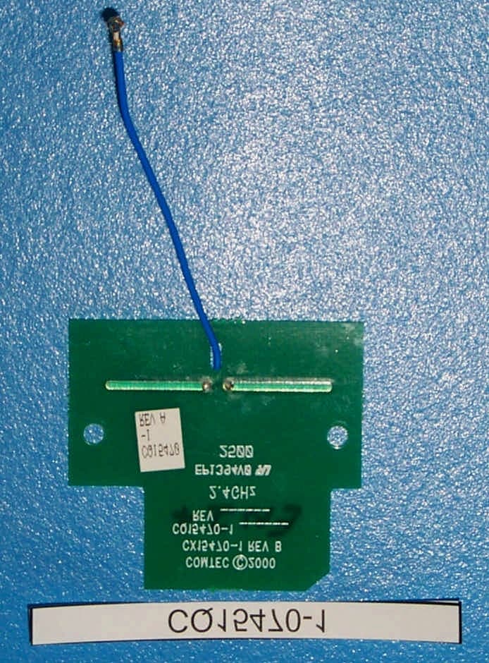
Click to zoom
Application Details
- Equipment Class
- DXX - Part 15 Low Power Communication Device Transmitter
- Date of Grant
- Oct 11, 2000
- Application Purpose
- Original Equipment
- Date of Application
- Oct 11, 2000
- Equipment Note
- Modular Transmitter
- Frequency Range
- 2481.92000000 - 2481.92000000
- Country
- United States
Documents & Files
Document Text
Text extracted from the exhibit documents filed with the FCC. Open a document above to read the original.
Users Manual
2400 Wireless 2.4 GHz Transceiver Part Number: CC15380-1 Features The Zebra 2400 Wireless is a 2.4 Ghz radio designed for OEM applications that oper- ate in the unlicensed FCC band between 2.4-2.5 Ghz. The 2400 Wireless can be used for communications where physical connection is not desired. The following objectives can be achieved with the 2400 Wireless, (i) provides a limited range radio (20-30 feet line of sight), (ii) minimizes parts count and associated cost, (iii) acts as a cable replacement when used together with Zebra Wireless printers. When combined with Zebra’s Intelligent Wireless Controller (part number CQ13867-1), the 2400 Wire- less can be attached to any RS232C port. To minimize integration headaches, the 2400 Wireless has modular FCC approval, which means that no additional FCC approval is required by the OEM providing an approved antenna is used. Note: The modular approval for this radio only applies for battery powered equipment. Installation of this radio into A.C. connected equipment requires additional regulatory approval. Please contact Zebra Technologies Corporation for details. Electrical Input Voltage:Vcc = 5 Volts +,-10% Power Dissipation:250 mW (receive mode) 350mW (transmit mode) <5 mW (sleep mode) Current Consumption:50 mA (receive mode) 70 mA (transmit mode) <1 mA (sleep mode) Operating Frequency:2.482 GHz Transmit Power Output:-10 dBm (typical) Receiver Sensitivity:-85 dBm (typical) Out of band interfering signal rejection:60 dB (typical) Baud rate:user selectable J1 Pin Assignments:Pin #Signal Name 1 Description Pin 1sleep/awake*1 = sleep Pin 2Vcc Pin 3RXDReceive Data Pin 4TX/RX*1 = transmit Pin 5No connect Pin 6TXDTransmit Data Pin 7GND Pin 8GND J2 Pin Assignments:Pin #Signal Name 1 Description (Optional)Pin 1GND Pin 2GND J3 Pin Assignments:Pin #Signal Name 1 Description (Optional)Pin 1GND Pin 2GND Actual Size 1. All signals are at CMOS levels RF FILTER TX SAW MODULE DATA BUFFERS RX SAW MODULE DATA BUFFERS CONTROL LOGIC TXD RXD SLEEP/ AWAKE* TX/RX* TX MIX RX MIX LOCAL OSCILLATOR 0.000 0.235 0.312 0.540 0.845 0.768 1.080 0.194 2.1891.364 2.3572.447 0.000 0.070 0.250 0.062 0.080 J1 J2 J3 1 8 .125, 2 places Antenna Connector 2.253 1 1 0.000 0.120 0.090 2400 Wireless Block Diagram SoftwareWhen the Intelligent Wireless Controller (P/N CQ13967-1) is not used, Zebra can provide C source code for a CS/CDMA collision avoidance communications protocol. This soft- ware supports multiple radio pairs operating in proximity to each other, and implements error detection, retries and radio address association. The radio address association algorithm is based on radio or product serial number. RegulatoryApprovals:FCC Modular, ID Number: I28MD-TRCV-24GHZ Canada:Canada RSS210 Certification # 37981032228A Product LabellingAny final product that contains this radio must have a Requirementspermanently affixed label visible from the outside of the product that says the following: “Contains FCC ID: I28MD-TRCV-24GHz.” PhysicalConnectors:Antenna - SSMT, M/A-COM part number 2367-5002-54 Data (J1) - 8 pin female, Samtec part number SLM-108-01-S-S Optional ground connectors (J2, J3)- 2 pin female, Samtec part number SLM-102-01-S-S Connectors mate with Samtec MTMS family. Part number is dependent on desired board spacing. Dimensions: ©2000 Zebra Technologies Corporation all rights reserved. Specifications for information purposes and are subject to change. WARNING: Changes or modifications to this radio not expressly approved by Zebra Technologies Corporation may void the user’s authority to operate the equipment under the modular approval with FCC ID# I28MD-TRCV-24GHZ. Likewise, the antenna used with this radio must be approved by Zebra for the modular approval to be valid. All products and brand names are trademarks of their respective companies. P/N AT 15380 10/2000 Rev. 1.2
Cover Letter(s)
Curtis-Straus LLC 527 Great Road Littleton, Massachusetts 01460 Tel: (978) 486-8880 Fax: (978) 486-8828 Web: http://www.curtis-straus.com e-mail: [email protected] CONFIDENTIAL October 5, 2000 Certification Department Re: Confidentiality for Zebra Technologies (FCC ID: I28MD-TRCV-24GHZ) Due to the proprietary design developed by Zebra that is unique to the industry, Zebra is requesting confidentiality for the following exhibits of Curtis-Straus report number EA0975-1 (FCC ID: I28MD-TRCV-24GHZ): Technical Description & Block Diagram Schematics Bill of Materials Please feel free to contact me with any questions. Best regards, Michael Buchholz Senior EMC Manager
Cover Letter(s)
Curtis-Straus LLC 527 Great Road Littleton, Massachusetts 01460 Tel: (978) 486-8880 Fax: (978) 486-8828 Web: http://www.curtis-straus.com e-mail: [email protected] October 11, 2000 Certification Department Re: FCC Part 15 Certification for Zoom Telephonics (FCC ID: I28MD-TRCV-24GHZ) We are submitting an application for modular approval of the Zebra Technologies model 2400 2.4GHz wireless transmitter. As per Public Notice DA 00-1407, the following steps have been taken to insure that I28MD-TRCV-24GHZ (referred to below as “the module”) meets the FCC requirements for a modular approval: 1. The module is completely shielded. Only the connectors are exposed. This has allowed the device to comply with Part 15 limits. 2. The TXDATA input is buffered on the module itself. 3. Input voltage variations on TXDATA will not effect the modulation or the transmitter output power. The module has it’s own on-board 3-volt regulator. All RF circuitry operates from the 3 volts. Fluctuations in the 5-volt supply to the module will not effect the modulation or the transmitter output power. 4. The antenna connector used on the module has only one manufacturer and is not readily available. We have used the same connector on previous modular approvals and the FCC has considered it a non-standard connector. In addition, the module will only be used in devices with internal antennas of the type specified in the application. These internal antennas require complete disassembly of the unit to access and are not user serviceable or user replaceable. Therefore the antenna system meets the requirements of Section 15.203. 5. The worst case antenna/module combination was tested inside an unmodified Zebra Encore 3 printer (the Encore 3 printer was used as support equipment to allow for easy operation of the transmitter). The Encore 3 printer has an entirely plastic case which provides no shielding to the module, antenna or data cable. The only port on the module, other than the antenna port, is a data/power port that was attached to an 11cm cable. Emissions were maximized by rotating the unit in all three orthogonal axes. There was no maximization of the module’s antenna because it is affixed to the module in such a way that it cannot be manipulated. AC line conducted emissions was not performed. This device is intended for use in battery power devices only. A statement in the users guide indicated that the approval is only valid in devices that are battery powered with no AC connection. 6. Each module will be labeled with the FCC ID# and warning message as shown on the AA15642-1 drawing which is included with this application. A sample label to be placed on Curtis-Straus LLC 527 Great Road Littleton, Massachusetts 01460 Tel: (978) 486-8880 Fax: (978) 486-8828 Web: http://www.curtis-straus.com e-mail: [email protected] the outside of the host unit is also provided. Instructions on host label content and placement are provided in the user’s manual. 7. There are no special compliance requirements for 15.249. 8. There are no applicable RF exposure requirements for section 15.249. Please feel free to contact me with any questions. Best regards, Michael Buchholz EMC Manager
External Photos
FCC Application for Zebra Technologies – External Photos •• FCC ID: I28MD-TRCV-24GHZ •• Report No. EA0975-1 28-Sept-00 Page 1 of 2 ______________________________________________________________________ External Photos FCC Application for Zebra Technologies – External Photos •• FCC ID: I28MD-TRCV-24GHZ •• Report No. EA0975-1 28-Sept-00 Page 2 of 2 ______________________________________________________________________ FCC Application for Zebra Technologies – External Photos •• FCC ID: I28MD-TRCV-24GHZ •• Report No. EA0975-1 28-Sept-00 Page 3 of 2 ______________________________________________________________________ 4.1.1 Antenna Photos: FCC Application for Zebra Technologies – External Photos •• FCC ID: I28MD-TRCV-24GHZ •• Report No. EA0975-1 28-Sept-00 Page 4 of 2 ______________________________________________________________________ FCC Application for Zebra Technologies – External Photos •• FCC ID: I28MD-TRCV-24GHZ •• Report No. EA0975-1 28-Sept-00 Page 5 of 2 ______________________________________________________________________ FCC Application for Zebra Technologies – External Photos •• FCC ID: I28MD-TRCV-24GHZ •• Report No. EA0975-1 28-Sept-00 Page 6 of 2 ______________________________________________________________________ FCC Application for Zebra Technologies – External Photos •• FCC ID: I28MD-TRCV-24GHZ •• Report No. EA0975-1 28-Sept-00 Page 7 of 2 ______________________________________________________________________
External Photos
FCC Application for Zebra Technologies – Internal Photos •• FCC ID: I28MD-TRCV-24GHZ •• Report No. EA0975-1 28-Sept-00 Page 1 of 2 ______________________________________________________________________ Internal Photos FCC Application for Zebra Technologies – Internal Photos •• FCC ID: I28MD-TRCV-24GHZ •• Report No. EA0975-1 28-Sept-00 Page 2 of 2 ______________________________________________________________________
ID Label/Location Info
FCC Application for Zebra Tech. – Label Info. •• FCC ID: I28MD-TRCV-24GHZ •• Report No. EA0975-1 28-Sept-00 Page 1 of 3 ______________________________________________________________________ Label Artwork This is a sample label to be affixed to the outside of the host unit. The warning required by 15.19(a)(5) is included in the label below. Instructions for the content and placement of the host’s label appear in the module’s user’s guide. FCC Application for Zebra Tech. – Label Info. •• FCC ID: I28MD-TRCV-24GHZ •• Report No. EA0975-1 28-Sept-00 Page 2 of 3 ______________________________________________________________________ This label will be affixed to the transmitter as shown in the drawing on the next page. FCC Application for Zebra Tech. – Label Info. •• FCC ID: I28MD-TRCV-24GHZ •• Report No. EA0975-1 28-Sept-00 Page 3 of 3 ______________________________________________________________________
Internal Photos
FCC Application for Zebra Technologies – Internal Photos •• FCC ID: I28MD-TRCV-24GHZ •• Report No. EA0975-1 28-Sept-00 Page 1 of 2 ______________________________________________________________________ Internal Photos FCC Application for Zebra Technologies – Internal Photos •• FCC ID: I28MD-TRCV-24GHZ •• Report No. EA0975-1 28-Sept-00 Page 2 of 2 ______________________________________________________________________
Test Report
MEASUREMENT/TECHNICAL REPORT Company - Model: Zebra Technologies 2400 Wireless 2.4Ghz transmitter FCC ID: I28MD-TRCV-24GHZ September 28, 2000 Description: This is a report to support a request for an original grant of equipment authorization. Equipment Type: Low Power Communications Device Transmitter (DXX) Report prepared for:Zebra Technologies 30 Plan Way Warwick, RI 02886-1012 Phone:(401) 739-5800 Fax:(401) 732-0145 Report prepared by:Chad A. Bell Curtis-Straus LLC 527 Great Road Littleton, MA 01460 Phone:978-486-8880 FAX:978-486-8828 FCC Application for Zebra Tech. •• FCC ID: I28MD-TRCV-24GHZ •• Report No. EA0975-1 28-Sept-00 ______________________________________________________________________ _____________________________________________________________ Curtis-Straus LLC •• 527 Great Road •• Littleton, MA •• TEL (978) 486-8880 •• FAX (978) 486-8828 page 2 of 15 Table of Contents INTRODUCTION..........................................................................................................................................................3 1.0STATEMENT OF CONFORMITY...............................................................................................................................5 2.0 GENERAL DESCRIPTION....................................................................................................................................6 2.1Product Description........................................................................................................................................6 2.2Related Submittal(s) Grants............................................................................................................................6 2.3Test Methodology............................................................................................................................................6 2.4Test Facility.....................................................................................................................................................6 2.5Test Equipment Used.......................................................................................................................................7 EXHIBIT 3......................................................................................................................................................................9 3.0MEASUREMENT RESULTS.....................................................................................................................................9 3.1Operating Frequency......................................................................................................................................9 3.2Electric Field Strength Radiation Measurements...........................................................................................9 3.3Emissions Plots.............................................................................................................................................12 FCC Application for Zebra Tech. •• FCC ID: I28MD-TRCV-24GHZ •• Report No. EA0975-1 28-Sept-00 ______________________________________________________________________ _____________________________________________________________ Curtis-Straus LLC •• 527 Great Road •• Littleton, MA •• TEL (978) 486-8880 •• FAX (978) 486-8828 page 3 of 15 Introduction This report is an application for Certification of a Modular Transmitter operating pursuant to Part 15.249 of the FCC Rules, Code of Federal Regulations 47. The model number covered by this report is the Zebra Technologies 2400 Wireless. This report is designed to demonstrate the compliance of this device with the requirements outlined in Part 15 of CFR 47 using the methods outlined in Part 2 of CFR 47. The current revision date, October 1,1998, of each Part has been used for technical requirements. The transmitter module under test is used in conjunction with five different antennas. Through pre-scan testing it was determined that the Encore 3 printer configuration is the worst case configuration. So a full scan was done on the Encore 3 printer configuration from 30Mhz to 25Ghz. Then all the emissions that were within 10dB of the limit in the Encore 3 printer configuration were rechecked in all the other products with their appropriate antennas. A fresh battery was used for each configuration. This Short-Range Radio Frequency (SRRF) transceiver module is used in conjunction with Manchester Encoding of the digital data that it transmits. Manchester Encoding is required for optimum operation of the RF Monolithics TR-1000 transceiver IC that is used in this design. Manchester encoding ensures a 50% ones density in the data stream by converting each bit into two bits, one of which is a 1 and the other a 0. This radio uses ON-OFF keying modulation. The transmitter (carrier) is on when the radio is transmitting a 1 and off when the radio is transmitting a 0. Combining the modulation scheme with the Manchester Encoding, the transmitter will only be on 50% of the time during any transmission. According to 47 CRF Part 15.35, we are allowed to average our transmission over a pulse train up to 100 milliseconds in length. The averaging factor is based on the 50% on time of the transmitter: 20 log (.5) = -6.02 dB All intentional emissions from the transmitter will be averaged with this factor. The confidential information and descriptions included in this application are detailed descriptions of the products, block diagrams, component specifications, and schematic diagrams. We hereby respectfully request under the provision of section 0.457d of the code that the documents listed below be held confidential. Exhibit 6.1: Technical Descriptions and Block Diagrams Exhibit 6.2: Schematics Exhibit 6.3: Bill of Materials Zebra Technologies is requesting that the Technical Descriptions, Block Diagrams, Schematics FCC Application for Zebra Tech. •• FCC ID: I28MD-TRCV-24GHZ •• Report No. EA0975-1 28-Sept-00 _______________________________________…
Text truncated - open the document above for the full version.
Test Report
FCC Application for Zebra Technologies – Duty Cycle •• FCC ID: I28MD-TRCV-24GHZ 28-Sept-00 Report No. EA0975-1 Page 1 of 1 ______________________________________________________________________ Duty-Cycle Calculation and Justification: 2.4 GHz SRRF RADIO Justification for Duty Cycle Averaging This Short-Range Radio Frequency (SRRF) transceiver module is used in conjunction with Manchester Encoding of the digital data that it transmits. Manchester Encoding is required for optimum operation of the RF Monolithics TR-1000 transceiver IC that is used in this design. Manche ster encoding ensures a 50% ones density in the data stream by converting each bit into two bits, one of which is a 1 and the other a 0. This radio use ON-OFF keying modulation. The transmitter (carrier) is on when the radio is transmitting a 1 and off when the radio is transmitting a 0. Combining the modulation scheme with the Manchester Encoding, the transmitter will only be on 50% of the time during any transmission. According to 47 CRF Part 15.35, we are allowed to average our transmission over a pulse train up to 100 milliseconds in length. The averaging factor is based on the 50% on time of the transmitter: 20 log (.5) = -6.02 dB All intentional emissions from the transmitter will be averaged with this factor.
Test Report
Responses to TCB questions Subject: Re: I28MD-TRCV-24GHZ Date: Wed, 11 Oct 2000 11:25:08 -0400 From: Michael Buchholz <[email protected]> Organization: curtis-straus To: Certification Manager <[email protected]> References: 1 The following items have been addressed and appear below or in the new version of the report as appropriate. The CD and hard copy will follow shortly. Mike Certification Manager wrote: > We have the following issues to resolve before I can grant this > application: > > 1. I need a 731 form filled out and signed by you or Zebra. In report packet > > > 2. I need an exhibit entitled "Letter requesting confidentiality" I > know you put it in the test report. I need a letter. In report packet / on CD > > > 3. In accordance with the Public Notice DA 00-1407 on modular > transmitters, you must submit a cover letter requesting modular > approval. You must address the numbered points in the Public Notice. > You appear to have an analysis as part of the test report. I need a > cover letter to upload. It is also unclear how you intend to meet > requirment 6 for the FCC ID label to be on the outside of any device > into which this module is installed. The manual doesn't tell buyers > that they need to do this. Cover letter produced, manual updated > > > 4. RF Exposure. You state that the unit must be kept 5.4 cm away from > the user's body but this is not stated in the manual that they supply to > users of this device. What is to keep someone from putting this modular > transmitter into a body worn device? You need a caution statement in > the manual. No RF exposure requirements - exhibit eliminated > > > 5. Please reproduce for me the equation you used for RF exposure in an > "RF exposure exhibit". Don't make me go to other FCC documents to look > it up. Exhibit eliminated > > > 6. Your external photos exhibit is too large. The FCC will soon reduce > allowable file size to 2M and they complain whenever I send in anything > over that now. Please use adobe to produce a photo exhibit which is > under 2M in size. File size reduced > > > 7. In the future, please submit all pdf files. These word files are > larger than they need to be and that translates to extra upload time. PDFs provided > > > 8. As this is a modular approval, you need to test the unit in a > standalone configuration as you said you did on page 5 of the test > report. But I see no data for the standalone configuration. Please > provide it. I particularly need to verify how you complied with item 5 > of the public notice. What cables were attached to the module? Where > they shielded or unshielded? How long were they? Addressed in modular approval cover letter and report > > > 9. The user's manual does not contain the required cautionary statement > of 15.21. It must be added to the user's manual. Please respond. Statement is in fine print on bottom of second page. > > > 10. How was the EUT antenna position adjusted to maximize emissions? Antenna cannot be moved as it is integrated into the module > > > 11. Was the EUT rotated through three orthagonal axes to maximize > emissions? All orthogonal axes were measured. The worst case was recorded. > > > -- > Jon D. Curtis > Certification Manager > > Curtis-Straus LLC > Telecom Certification Body > 527 Great Road > Littleton, MA 01460 > USA > t:978-486-8880 f:978-486-8828 -- Michael Buchholz Senior EMC Manager ----------------------------------------------------------- Curtis-Straus LLC Voice: 978.486.8880 x264 527 Great Road Fax: 978.486.8828 Littleton, MA 01460 http://www.curtis-straus.com -----------------------------------------------------------
Test Setup Photos
FCC Application for Zebra Technologies - Test Setup Photos •• FCC ID: I28MD-TRCV-24GHZ •• Report No. EA0975-1 28-Sept-00 __________________________________________________________________________________________ Page 1 of 10 Test Setup Photographs: Radiated Emissions Side 1 on the Encore 3 printer FCC Application for Zebra Technologies - Test Setup Photos •• FCC ID: I28MD-TRCV-24GHZ •• Report No. EA0975-1 28-Sept-00 __________________________________________________________________________________________ Page 2 of 10 Radiated Emissions Side 2 on the Encore 3 printer FCC Application for Zebra Technologies - Test Setup Photos •• FCC ID: I28MD-TRCV-24GHZ •• Report No. EA0975-1 28-Sept-00 __________________________________________________________________________________________ Page 3 of 10 Radiated Emissions Side 1 on the Encore 2 plus printer FCC Application for Zebra Technologies - Test Setup Photos •• FCC ID: I28MD-TRCV-24GHZ •• Report No. EA0975-1 28-Sept-00 __________________________________________________________________________________________ Page 4 of 10 Radiated Emissions Side 2 on the Encore 2 plus printer FCC Application for Zebra Technologies - Test Setup Photos •• FCC ID: I28MD-TRCV-24GHZ •• Report No. EA0975-1 28-Sept-00 __________________________________________________________________________________________ Page 5 of 10 Radiated Emissions Side 1 on the Cameo 3 printer FCC Application for Zebra Technologies - Test Setup Photos •• FCC ID: I28MD-TRCV-24GHZ •• Report No. EA0975-1 28-Sept-00 __________________________________________________________________________________________ Page 6 of 10 Radiated Emissions Side 2 on the Cameo 3 printer FCC Application for Zebra Technologies - Test Setup Photos •• FCC ID: I28MD-TRCV-24GHZ •• Report No. EA0975-1 28-Sept-00 __________________________________________________________________________________________ Page 7 of 10 Radiated Emissions Side 1 on the Cameo 2 printer FCC Application for Zebra Technologies - Test Setup Photos •• FCC ID: I28MD-TRCV-24GHZ •• Report No. EA0975-1 28-Sept-00 __________________________________________________________________________________________ Page 8 of 10 Radiated Emissions Side 2 on the Cameo 2 printer FCC Application for Zebra Technologies - Test Setup Photos •• FCC ID: I28MD-TRCV-24GHZ •• Report No. EA0975-1 28-Sept-00 __________________________________________________________________________________________ Page 9 of 10 Radiated Emissions Side 1 on the Dome Antenna FCC Application for Zebra Technologies - Test Setup Photos •• FCC ID: I28MD-TRCV-24GHZ •• Report No. EA0975-1 28-Sept-00 __________________________________________________________________________________________ Page 10 of 10 Radiated Emissions Side 2 on the Dome Antenna
Contact Information
Applicant
Jay Cadiz(Sr. Manager, Regulatory)
Technical Contact
Curtis-StrausMichael Buchholz
[email protected]978 486 8880
527 Great Road · Littleton, Massachusetts · United States
Non-Technical Contact
Curtis-StrausMichael Buchholz
[email protected]978 486 8880
Test Firm
Curtis-Straus LLCJonathan Stewart
Technical Specifications
| # | Rule Parts | Frequency Range | Power Output |
|---|---|---|---|
| 1 | 15C | 2.48 GHz - 2.48 GHz | - |
Other Applications from Zebra Technologies Corporation
I28-WYSBHVDXP
May 19, 2021WLAN/BTLE module
Equipment Class
DTS - Digital Transmission System
I28-EYSNSNZWWZ1
May 04, 2021BT5 Radio Module
Equipment Class
DTS - Digital Transmission System
I28MD-FXLAN11AC
Nov 22, 2015Wireless 802.11ac + Bluetooth Module
Equipment Class
DSS - Part 15 Spread Spectrum Transmitter
I28MD-ZBRBLE
Nov 19, 2015Bluetooth Low Energy Module
Equipment Class
DTS - Digital Transmission System
I28MD-ZBR7BTLE
Jan 19, 2015Bluetooth 4.0 LE Module
Equipment Class
DSS - Part 15 Spread Spectrum Transmitter