I28RFID-M2HFRFID Printer Module
Zebra Technologies Corporation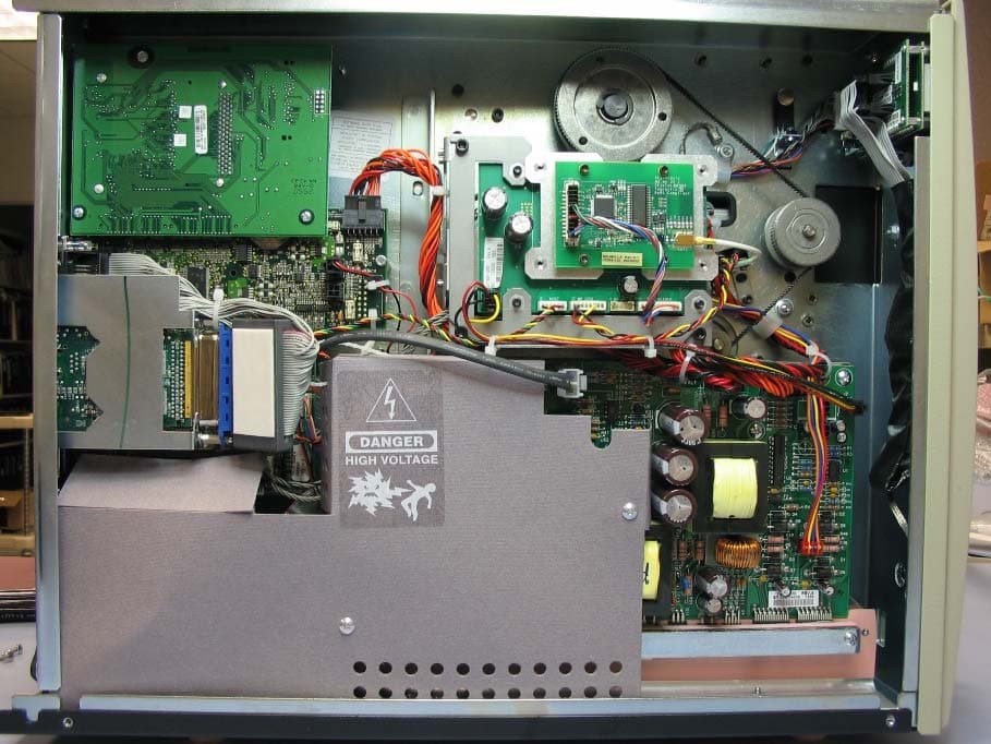
Click to zoom
Application Details
- Equipment Class
- DXT - Part 15 Low Power Transceiver, Rx Verified
- Date of Grant
- Aug 16, 2006
- Application Purpose
- Original Equipment
- Date of Application
- Aug 16, 2006
- Equipment Note
- RFID Printer Module
- Frequency Range
- 13.56000000 - 13.56000000
- Country
- United States
Documents & Files
Document Text
Text extracted from the exhibit documents filed with the FCC. Open a document above to read the original.
Users Manual
Zebra ® XiIIIPlus™/R110Xi™/R170Xi™ User Guide © 2005 ZIH Corp. The copyrights in this manual and the software and/or firmware in the label printer described therein are owned by ZIH Corp. Unauthorized reproduction of this manual or the software and/or firmware in the label printer may result in imprisonment of up to one year and fines of up to $10,000 (17 U.S.C.506). Copyright violators may be subject to civil liability. This product may contain ZPL ® , ZPL II ® , and ZebraLink™ programs; Element Energy Equalizer ® Circuit; E 3 ® ; and AGFA fonts. Software © ZIH Corp. All rights reserved worldwide. ZebraLink and all product names and numbers are trademarks, and Zebra, the Zebra logo, ZPL, ZPL II, Element Energy Equalizer Circuit, and E 3 Circuit are registered trademarks of ZIH Corp. All rights reserved worldwide. All other brand names, product names, or trademarks belong to their respective holders. Proprietary Statement This manual contains proprietary information of Zebra Technologies Corporation and its subsidiaries (“Zebra Technologies”). It is intended solely for the information and use of parties operating and maintaining the equipment described herein. Such proprietary information may not be used, reproduced, or disclosed to any other parties for any other purpose without the express, written permission of Zebra Technologies. Product Improvements Continuous improvement of products is a policy of Zebra Technologies. All specifications and designs are subject to change without notice. Liability Disclaimer Zebra Technologies takes steps to ensure that its published Engineering specifications and manuals are correct; however, errors do occur. Zebra Technologies reserves the right to correct any such errors and disclaims liability resulting therefrom. Limitation of Liability In no event shall Zebra Technologies or anyone else involved in the creation, production, or delivery of the accompanying product (including hardware and software) be liable for any damages whatsoever (including, without limitation, consequential damages including loss of business profits, business interruption, or loss of business information) arising out of the use of, the results of use of, or inability to use such product, even if Zebra Technologies has been advised of the possibility of such damages. Some jurisdictions do not allow the exclusion or limitation of incidental or consequential damages, so the above limitation or exclusion may not apply to you. iii Declaration of Conformity 12/2/05XiIIIPlus/R110Xi/R170Xi User Guide13383L-002 Rev. A Declaration of Conformity I have determined that the Zebra printers identified as the XiIIIPlus™ Series 110XiIIIPlus, R110Xi, 140XiIIIPlus, 170XiIIIPlus, R170Xi, 220XiIIIPlus manufactured by: Zebra Technologies Corporation 333 Corporate Woods Parkway Vernon Hills, Illinois 60061-3109 U.S.A. Have been shown to comply with the applicable technical standards of the FCC For Home, Office, Commercial, and Industrial use If no unauthorized change is made in the equipment, and if the equipment is properly maintained and operated. Compliance Information iv 13383L-002 Rev. AXiIIIPlus/R110Xi/R170Xi User Guide12/2/05 Compliance Information FCC Compliance Statement This device complies with Part 15 rules. Operation is subject to the following two conditions: 1.This device may not cause harmful interference, and 2.This device must accept any interference received, including interference that may cause undesired operation. The user is cautioned that any changes or modifications not expressly approved by Zebra Technologies could void the user’s authority to operate the equipment. To ensure compliance, this printer must be used with Shielded Communication Cables. FCC Radiation Exposure Statement (for printers with RFID encoders) This equipment complies with FCC radiation exposure limits set forth for an uncontrolled environment. This equipment should be installed and operated with minimum distance 20cm between the radiator and your body. This transmitter must not be co-located or operating in conjunction with any other antenna or transmitter. Canadian DOC Compliance Statement This Class B digital apparatus complies with Canadian ICES-003. Cet appareil numérique de la classe B est conforme à la norme NMB-003 du Canada. 12/2/05XiIIIPlus/R110Xi/R170Xi User Guide13383L-002 Rev. A Contents Declaration of Conformity . . . . . . . . . . . . . . . . . . . . . . . . . . . . . . . . . . . . . . . . . . . iii About This Document . . . . . . . . . . . . . . . . . . . . . . . . . . . . . . . . . . . . . . . . . . . . . . . 1 Who Should Use This Document . . . . . . . . . . . . . . . . . . . . . . . . . . . . . . . . . . . . . . . . . . . . 2 How This Document Is Organized . . . . . . . . . . . . . . . . . . . . . . . . . . . . . . . . . . . . . . . . . . . 2 Contacts . . . . . . . . . . . . . . . . . . . . . . . . . . . . . . . . . . . . . . . . . . . . . . . . . . . . . . . . . . . . . . . 3 Web Site . . . . . . . . . . . . . . . . . . . . . . . . . . . . . . . . . . . . . . . . . . . . . . . . . . . . . . . . . . . . 3 The Americas . . . . . . . . . . . . . . . . . . . . . . . . . . . . . . . . . . . . . . . . . . . . . . . . . . . . . . . . 3 Europe, Africa, Middle East, and India . . . . . . . . . . . . . . . . . . . . . . . . . . . . . . . . . . . . . 3 Asia Pacific . . . . . . . . . . . . . . . . . . . . . . . . . . . . . . . . . . . . . . . . . . . . . . . . . . . . . . . . . . 3 Document Conventions. . . . . . . . . . . . . . . . . . . . . . . . . . . . . . . . . . . . . . . . . . . . . . . . . . . . 4 1 • Introduction . . . . . . . . . . . . . . . . . . . . . . . . . . . . . . . . . . . . . . . . . . . . . . . . . . . . 7 Exterior View . . . . . . . . . . . . . . . . . . . . . . . . . . . . . . . . . . . . . . . . . . . . . . . . . . . . . . . . . . . . 8 Control Panel . . . . . . . . . . . . . . . . . . . . . . . . . . . . . . . . . . . . . . . . . . . . . . . . . . . . . . . . . . . 9 Con…
Text truncated - open the document above for the full version.
Cover Letter(s)
July 10, 2006 Federal Communications Commission 7435 Oakland Mills Road Columbia, MD 21046-1609 To Whom It May Concern: In reference to the application for FCC ID#: I28RFID-M2HF (13.56 MHz RFID encoder radio module), this device is being submitted for Limited MODULAR TRANSMITTER APPROVAL based on the guidelines in FCC Publication DA 00-1407. We believe that this transmitter meets or addresses all 8 criterions listed in DA 00-1407 as detailed in the paragraphs below. Note that I28RFID-M2HF is a radio module that will be used exclusively within products made by Zebra Technologies Corporation. 1) I28RFID-M2HF is based on a SkyeTek M2 RFID encoder radio module. The RF portion of the module is not shielded. Shielding is provided by the host device. 2) The host device provides buffered inputs on all digital lines. Overdriving one or more of the digital inputs will have no affect on the transmitter output. 3) The SkyeTek M2 accepts a regulated 5.3 VDC, which is provided by the host device, to the SkyeTek M2 module. Further, since the module will only be used in Zebra products, Zebra has full control of the power supply to the SkyeTek M2 module and will assure a 5.3 VDC supply. 4) I28RFID-M2HF will always be used with one of a family of approved antennas, all of which are mounted (with the radio) inside a finished printer or other Zebra product. None of these antennas is user accessible, nor is the antenna cable / connector user accessible; for these reasons the antennas can be considered to be permanently attached. All of the antennas in the family have been tested with the radio module as part of the limited modular approval; test results are included with the application. If the radio is to be used with a new antenna, further testing will be performed and a Class II permissive change will be obtained. 5) I28RFID-M2HF was tested in the host device. 6) I28RFID-M2HF will carry a label containing its FCC ID number. Additionally “Contains FCC ID: I28RFID- M2HF” will appear on the external label of the product the radio is mounted it. All products containing this module will have this statement clearly visible. Examples of both the internal and external labels have been provided as part of the application. 7) I28RFID-M2HF will only be used with Zebra Technologies products; this includes printers built by Zebra that are branded for other companies. Thus Zebra will maintain full control over the use of the module and can guarantee that all conditions for use will be met in any product that the module is installed in. 8) The products that I28RFID-M2HF will be used in will be at least 20 cm away from any body part. Sincerely, Gus Medina Compliance Engineer Zebra Technologies Corporation
Cover Letter(s)
Secure 13.56MHz OEM Reader/Writer APPLICATIONS: • Contactless Payment • ePedigree • Kiosk / Vending • Encrypted Authentication FEATURES : • SkyeModule Compatibility • Software Adjustable Host Interfaces: UART (TTL), SPI, USB • 4 GPIO Capable • On-board ISO 7816 Slot with I/O Lines and SW Support for Additional Slot • Simple & Intuitive API BENEFITS : • Common Size, Connection Method, and Software Interface with the SkyeModule M9 UHF Reader • Easy to Embed • Drive Peripherals (PLC, LED, Sensor) • Removable Storage of Eencryption Algorithms and Key Storage • Fast Integration /Time to Market Product Overview The SkyeModule ™ M2 is a state-of-the-art secure HF RFID reader platform that provides several options for the implementation of cryptographic functions. The M2 is a 13.56MHz OEM module capable of reading and writing to transponders based on ISO 14443 (parts 2, 3, and 4) and ISO 15693 air-interface protocols. Support for security features of MiFare, in addition to standardized encryption algorithms (DES, 3DES, and AES), secure hash functions (SHA and MD5), and an internal Pseudo-Random Number Generator (PRNG) offers industry-leading security functions. An ISO 7816 smart card slot allows for supplementary security protocols and key storage through a replaceable smart card (SAM) while an interface is supplied for the control of an off-board additional ISO 7816 card. The M2 features an on-board antenna optimized to support the data rates of 106, 212, and 424 kbps. A standard 50 Ω antenna output offers the ability to attach an external antenna to enable optimization of read range/ rate. The M2 has three host-interface options USB, UART (TTL) and SPI which are software selectable to facilitate both loosely and tightly coupled integrations. The M2 has 4 programmable GPIO pins for I/O connections to peripherals. Serial data rates are adjustable from 4.8 to 115.2 kbps. Field upgradeable firmware provides forward compatibility for adding future tag protocols, security features, and customized enhancements. Applications The SkyeModule M2 has been created specifically for contactless transactions requiring a high level of security with the flexibility to encompass a variety of vertical markets. The M2 offers a simple platform for migration from contact smart card technology to contactless smart card technology. • Contactless Payment • ePedigree • Kiosk / Vending • Encrypted Authentication rfid as a feature SkyeModule M2 1 See transponder datasheets for complete details www.skyetek.com About Skyetek: SkyeTek, Inc., maker of ReaderWare™, is the leading supplier of RFID reader software and reference designs that enable the pervasive adoption of RFID technology. SkyeTek’s Tagnostic™ reader technology works with most industry standard tags and smart labels, its low power require- ments and a small form factor make it the optimal choice for embedding into new or existing products. SkyeTek’s RFID reader technology is available in several formats including reader modules, hardware reference designs, and the ReaderWare ™ software suite. SkyeTek markets to OEM customers in targeted vertical markets with several high-volume licensing options available. For more information about SkyeTek, visit www.skyetek.com or call 720-565-0441. SkyeTek is based in Colorado. Our Address: 11030 Circle Point Road Ste 300, Westminster, CO 80020 USA Copyright © 2005 SkyeTek, Inc. Tagnostic ™, ReaderWare™, and SkyeModule™ are trademarks or registered trademarks of SkyeTek, Inc. All other trademarks or brand names are the properties of their respective holders. Features and specifications are subject to change without notice. SkyeModule M2 Transponder Support 1 Product Name Memory (bits) Manufacturer Air-Interface 1 Mifare Ultralight 0.5k Philips ISO14443A Mifare 1k, 4k Philips, Infineon ISO14443A DESFire 32k Philips ISO14443A ProX 4k, 8k, 16k Philips ISO14443A SmartMX 36k, 72k Philips ISO14443A SR176 176 ST Microelectronics ISO14443B AT88RF020 2K Atmel ISO14443B Tag-It HF-I 2K Texas Instruments ISO15693 I-Code SLI(2) 1K Philips ISO15693 My-d 2k,10K Infineon ISO15693 LRI512 0.5K ST Microelectronics ISO15693 Frequency 13.56 MHz +/- 7 kHz Physical Length: 59mm Width: 36mm Height: 5mm (9mm with ISO 7816 slot) Host Communication Interfaces/ Data Rates RS232 (Serial UART): 4.8-115.2 kbps SPI: up to 5MHz USB: 2.0 Full Speed (12 Mb/s) Supply Voltage 5.0 V Compliance FCC Part 15.225 (pending) EN 300 330 (pending) RoHS Transponder Communication Rate ISO 14443A: 106, 212, 424 kbps ISO 14443B: 106 kbps ISO 15693: 26 kbps Accessories Host Interface board: RS232 circuitry and connector, USB type B connector, an integrated antenna, and external antenna MMCX connector (95mmx95mm) Current Consumption Sleep Mode- 60μA Idle Mode- 10mA Scan Mode- 200mA Antenna Options Internal or 50 Ω output for external connection Effective Range Internal Antenna, 48 mm x 76 mm inlay, 14443 = 7cm External Antenna, 48 mm x 76 mm inlay, 14443 = 14cm (Individual results will vary with environment) Other Offerings from SkyeTek SkyeTek provides a variety of reader technology at both 13.56 MHz (HF) and 860- 960 MHz (UHF). ReaderDNA HF, a comprehensive reference design, is available for component level integration of the technology including complete design files, BOM, and test fixture. ReaderWare, the embedded software intelligence of the RFID reader, is available to ReaderDNA customers. The SkyeModule M8 is a low power, compact, UHF reader compatible with EPC and ISO transponders. All SkyeModules are controlled via the SkyeTek Protocol, a powerful but simple communication protocol that grants the user access to all features of an RFID transponder. Further, they have been designed with flexible and modular embedded software that allows one to select only the desired features.
Cover Letter(s)
FCC ID: I28RFID-M2HF D.L.S. ELECTRONIC SYSTEMS, INC. 1250 Peterson Drive Wheeling, Illinois 60090 FCC Authorization & Evaluation Division 7435 Oakland Mills Road Columbia, Maryland 21045-0429 Gentlemen: We are submitting for Zebra Technologies Corporation, Inc., a R110Xi HF Transmitter, Model Number: M2, with a FCC ID: I28RFID-M2HF for Certification. This unit has been tested and complies to Part 15, Subpart C. If there are any questions in regards to this application, please call D.L.S. Electronic Systems, Inc. at (847) 537 6400. Enclosed you will find a copy of our test report with the information and results of tests that is required under Part 15, Section 15.231. Thank you for your assistance in this matter. Sincerely, Arnom C. Rowe EMC-001375-NE DLS/sr
Cover Letter(s)
Letter of Agency Date: July 25, 2006 American Telecommunications Certification Body, Inc. 6731 Whittier Avenue Suite C110 McLean, VA 22101 To Whom It May Concern: Please be advised that Zebra Technologies Corporation authorizes D.L.S. Electronic Systems, Inc. to act on our behalf, until otherwise notified, for applications submitted to American Telecommunications Certification Body, Inc. (ATCB). We certify that we are not subject to denial of federal benefits, that includes FCC benefits, pursuant to Section 5301 of the Anti-Drug Abuse ACT of 1988, U.S.C. 862. Further, no party, as defined in 47 CFR 1.2002(b), to the application is subject to denial of federal benefits, that includes FCC benefits. Thank you for your attention to this matter. Signatory, Arnom C. Rowe EMC ENGINEER EMC-001375-NE D.L.S. Electronic Systems, Inc. FCC Labeling Requirements and Information Date: July 25, 2006 American Telecommunications Certification Body, Inc. 6731 Whittier Avenue Suite C110 McLean, VA 22101 RE: FCC Labeling Requirements FCC ID: I28RFID-M2HF The following label information is required by the FCC Rules and Regulations for certified devices. Also attached, please find marketing information required by the FCC Rules and Regulations. Thank you for your attention to these matters. Sincerely, Arnom C. Rowe EMC ENGINEER EMC-001375-NE D.L.S. Electronic Systems, Inc. Modification Letter Date: July 25, 2006 American Telecommunications Certification Body, Inc. 6731 Whittier Avenue Suite C110 McLean, VA 22101 RE: Certification Application FCC ID: I28RFID-M2HF Please be advised that the following information is a list of modifications that will be included in the production process for the above-referenced equipment. Change 1: There were no modifications made during testing. Change 2: Change 3: Change 4: Change 5: Change 6: Change 7: Change 8: Change 9 Change 10: Thank you for your attention to this matter. Signatory Arnom C. Rowe EMC ENGINEER EMC-001375-NE D.L.S. Electronic Systems, Inc. Manufacturer’s Letter Date: July 25, 2006 American Telecommunications Certification Body, Inc. 6731 Whittier Avenue Suite C110 McLean, VA 22101 RE: Certification Application FCC ID: I28RFID-M2HF To Whom It May Concern: Please be advised that the manufacturer will ensure that the above-referenced model will be manufactured in accordance with the FCC Rules and Regulations. Thank you for your attention to this matter. Signatory Arnom C. Rowe EMC ENGINEER EMC-001375-NE D.L.S. Electronic Systems, Inc.
Cover Letter(s)
Request for Confidentiality Date: July 25, 2006 American Telecommunications Certification Body, Inc. 6731 Whittier Avenue Suite C110 McLean, VA 22101 RE: Certification Application FCC ID: I28RFID-M2HF Pursuant to 47 CFR Section 0.459 Zebra Technologies Corporation understands that requests for non disclosure and confidential treatment is being made for the following information as stated under the Code of Federal Regulations Chapter 47, Part 0.459 and behalf of APPLICANT NAME: • Block Diagram • Schematics • Technical Product Description The above materials contain trade secrets, proprietary and technical information that would customarily be guarded from competitors under 47 CFR section 0.457(d)(2). Disclosure or publication of any portion of this company confidential material to other parties could cause substantial competitive harm and provide unjustified benefits for competitors. Zebra Technologies Corporation understands that pursuant to 47 CFR section 0.457(d)(1)(ii) disclosure of the applicant and all accompanying documentation will not be made before the date of the grant. Thank you for your attention to this matter. Signatory Arnom C. Rowe EMC ENGINEER EMC-001375-NE D.L.S. Electronic Systems, Inc.
External Photos
Zebra Technologies Corporation RFID Encoder Model #: M2 Description: Encoder – Top view FCC & IC ID label location Zebra Technologies Corporation RFID Encoder Model #: M2 Description: Encoder – Bottom View Zebra Technologies Corporation RFID Encoder Model #: M2 Description: Antenna/Coupler – Top & Bottom View Zebra Technologies Corporation RFID Encoder Model #: M2 Description: Assembly with host device interface board. Zebra Technologies Corporation RFID Encoder Model #: M2 Description: Encoder installed in host. Zebra Technologies Corporation RFID Encoder Model #: M2 Description: Encoder installed in host (close-up).
ID Label/Location Info
Zebra Technologies Corporation RFID Encoder Model #: M2 Description: FCC Label 0.75 inches 0.25 inches Zebra Technologies Corporation RFID Encoder Model #: M2 Description: Encoder – Top view FCC & IC ID label location
Internal Photos
Zebra Technologies Corporation RFID Encoder Model #: M2 Description: Encoder – Top view FCC & IC ID label location Zebra Technologies Corporation RFID Encoder Model #: M2 Description: Encoder – Bottom View Zebra Technologies Corporation RFID Encoder Model #: M2 Description: Antenna/Coupler – Top & Bottom View Zebra Technologies Corporation RFID Encoder Model #: M2 Description: Assembly with host device interface board. Zebra Technologies Corporation RFID Encoder Model #: M2 Description: Encoder installed in host. Zebra Technologies Corporation RFID Encoder Model #: M2 Description: Encoder installed in host (close-up).
RF Exposure Info
RF Exposure Exhibit for Zebra I28RFID-M2HF Portable Devices are defined as a transmitting device designed to be used so that the radiating structure(s) of the device is in contact with the body of the user or nearby persons. Therefore, this device is classified under section 2.1093 as a “portable” device. Although this device is categorically excluded from RF exposure evaluation under Part 2, it can be shown that the device meets the limits used for evaluating other devices (those which are not excluded) under this section. Section 2.1093(d-2) for portable devices state that the limits for general population/uncontrolled exposure is .08 W/kg as averaged over the whole-body and spatial peak SAR not exceeding 1.6 W/kg as average over any 1 gram of tissue. The FCC OET Bulletin 65 Section 2 can be used to determine compliance with guidelines for human exposure to RF radiation. We will use equation 3 of that section for predicting RF fields. S = PG 4πR 2 S = power density (units e.g. mW/cm 2 ) P = power into to the antenna (or power output) (units e.g. mW) G = power gain of the antenna (worst case = 1) R = distance to the center of antenna (units e.g. cm) The highest power measurement for this device is 47.3 dBuV. For this prediction we will use a worst-case power of –59.7 dBm or 1.072 nW. Since the device is “portable”, we will use a worst-case distance of 20 cm. For worst-case antenna gain, we will use a gain of one. Using equation 3 of OET Bulletin 65 Section 2, the power density is calculated to be 0.000000000213 mW/cm 2 . This is well within the limit given in 2.1093 (d-2).
RF Exposure Info
RF Exposure Exhibit for Zebra I28RFID-M2HF Mobile Devices are defined as a transmitting device designed to be used in other than fixed locations and generally be used in such a way that a separation distance of at least 20 centimeters is normally maintained between the transmitter’s radiating structure(s) and the body of the user or nearby persons. Therefore, this device is classified under section 2.1091 as a “mobile” device. Although this device is categorically excluded from RF exposure evaluation under Part 2, it can be shown that the device meets the limits used for evaluating other devices (those which are not excluded) under this section. Section 2.1091 for mobile devices state that the limits are given in 1.1310. The limit given in 1.1310 for general population/uncontrolled at 13.56 MHz is a Maximum Permissible Exposure (MPE) limit of (180/f 2 ) mW/cm 2 . For 13.56 MHz this limit is 0.979 mW/cm 2 . The FCC OET Bulletin 65 Section 2 can be used to determine compliance with guidelines for human exposure to RF radiation. We will use equation 3 of that section for predicting RF fields. S = PG 4πR 2 S = power density (units e.g. mW/cm 2 ) P = power into to the antenna (or power output) (units e.g. mW) G = power gain of the antenna (worst case = 1) R = distance to the center of antenna (units e.g. cm) The highest power measurement for the M2 RFID Encoder is 47.3 dBuV. For this prediction we will use a worst-case power of -59.7 dBm or 1.072 nW. Since the device is “mobile”, we will use a worst-case distance of 20 cm. For worst-case antenna gain, we will use a gain of one. Using equation 3 of OET Bulletin 65 Section 2, the power density is calculated to be 0.000000000213 mW/cm 2 . This is well within the limit given in 1.1310.
Test Report
1250 Peterson Dr., Wheeling, IL 60090 Company: Zebra Technologies Corporation Model Tested: M2 Report Number: 12350 FCC Rules and Regulations / Intentional Radiators Operational in the Band 13.553-13.567 MHz Part 15, Subpart C, Section 15.225 THE FOLLOWING ''MEETS'' THE ABOVE TEST SPECIFICATION Formal Name: Zebra M2 Kind of Equipment: RFID Encoder for use in Zebra printers Test Configuration: Limited Modular Approval (Tested at 120 vac, 60 Hz) Model Number(s): M2 Model(s) Tested: M2 Serial Number(s): NA Date of Tests: June 30 and July 5 & 6, 2006 Test Conducted For: Zebra Technologies Corporation 333 Corporate Woods Parkway Vernon Hills, Illinois 60061 NOTICE: “This report must not be used by the client to claim product endorsement by NVLAP or any agency of the U.S. Government”. Please see the "Additional Description of Equipment Under Test" page listed inside of this report. This report must not be reproduced (except in full), without the approval of D.L.S. Electronic Systems. Page - 1 - 1250 Peterson Dr., Wheeling, IL 60090 Company: Zebra Technologies Corporation Model Tested: M2 Report Number: 12350 SIGNATURE PAGE Report By: Arnom C. Rowe Test Engineer EMC-001375-NE Reviewed By: William Stumpf OATS Manager Approved By: Brian Mattson General Manager Company Official: Zebra Technologies Corporation Page - 2 - 1250 Peterson Dr., Wheeling, IL 60090 Company: Zebra Technologies Corporation Model Tested: M2 Report Number: 12350 TABLE OF CONTENTS i. Cover Page..........................................................................................................................................1 ii. Signature Page....................................................................................................................................2 iii. Table of Contents...................................................................................................................................3 iv. NVLAP Certificate of Accreditation..............................................................................................5 1.0 Summary of Test Report.................................................................................................................6 2.0 Introduction.....................................................................................................................................6 3.0 Object..............................................................................................................................................6 4.0 Test Set-Up.....................................................................................................................................7 5.0 Test Equipment...............................................................................................................................8 6.0 Ambient Measurements..................................................................................................................9 7.0 Description of Test Sample...........................................................................................................10 8.0 Additional Description of Test Sample......................................................................................... 11 9.0 Photo Information and Test Set-Up..............................................................................................12 10.0 Radiated Photos Taken During Testing........................................................................................ 13 10.0 Power Line Conducted Photos Taken During Testing.................................................................16 11.0 Results of Tests.............................................................................................................................17 12.0 Conclusion....................................................................................................................................17 TABLE 1 – EQUIPMENT LIST..............................................................................................................18 Page -3- 1250 Peterson Dr., Wheeling, IL 60090 Company: Zebra Technologies Corporation Model Tested: M2 Report Number: 12350 TABLE OF CONTENTS Appendix A – Electric Field Radiated Emissions Test............................................................................. 20 1.0 Conducted Emission Measurements............................................................................................. 21 1.0 Conducted Data and Charts aken during testing...........................................................................22 2.0 Field Strength of Spurious Emission Measurements....................................................................27 2.0 Radiated Data and Charts taken of the Fundamental Emissions (Antenna #1 / Without Cutter). 28 2.0 Radiated Data and Charts taken of the Fundamental Emissions (Antenna #2 / Without Cutter). 32 2.0 Radiated Data and Charts taken of the Fundamental Emissions (Antenna #1 / With Cutter)......36 2.0 Radiated Data and Charts taken of the Fundamental Emissions (Antenna #2 / With Cutter)......40 2.0 Radiated Data and Charts for Spurious Emissions (Antenna #1 / Without Cutter)......................44 2.0 Radiated Data and Charts for Spurious Emissions (Antenna #2 / Without Cutter)......................51 2.0 Radiated Data and Charts for Spurious Emissions (Antenna #1 / With Cutter)...........................58 2.0 Radiated Data and Charts for Spurious Emissions (Antenna #2 / With Cutter)...........................65 3.0 ISO 15693 Emission Mask Frequency Stability – PART 2.1055a Temperature.........................72 3.0 ISO15693 Emission Mask Graphs for Frequency Stability when varying the Temperature.......73 8.0 ISO 15693 Emission Mask – Voltage Variation (PART 2.1055d)...............................................82 8.0 ISO15693 Emission Mask Graph(s) Taken for Frequency Stability (Voltage Variation)............83 9.0 MIFARE Emission Mask Frequency Stability – Temperature (PART 2.105…
Text truncated - open the document above for the full version.
Test Setup Photos
Company: Zebra Technologies Corp. Model Tested: M2 FCC ID: I28RFID-M2HF AC Line Conducted Company: Zebra Technologies Corp. Model Tested: M2 FCC ID: I28RFID-M2…
Text truncated - open the document above for the full version.
Contact Information
Applicant
Jay Cadiz(Sr. Manager, Regulatory)
Technical Contact
DLS Electronic SystemsArnie Rowe
[email protected]847-537-6400
1250 Peterson Drive · Wheeling, Illinois · United States
Test Firm
DLS Electronic Systems, Inc.William Stumpf
Technical Specifications
| # | Rule Parts | Frequency Range | Power Output | Tolerance |
|---|---|---|---|---|
| 1 | 15C | 13.56 MHz - 13.56 MHz | - | 0.0100000000 % |
Other Applications from Zebra Technologies Corporation
I28-WYSBHVDXP
May 19, 2021WLAN/BTLE module
Equipment Class
DTS - Digital Transmission System
I28-EYSNSNZWWZ1
May 04, 2021BT5 Radio Module
Equipment Class
DTS - Digital Transmission System
I28MD-FXLAN11AC
Nov 22, 2015Wireless 802.11ac + Bluetooth Module
Equipment Class
DSS - Part 15 Spread Spectrum Transmitter
I28MD-ZBRBLE
Nov 19, 2015Bluetooth Low Energy Module
Equipment Class
DTS - Digital Transmission System
I28MD-ZBR7BTLE
Jan 19, 2015Bluetooth 4.0 LE Module
Equipment Class
DSS - Part 15 Spread Spectrum Transmitter