I28RFID-R110XI-02RFID High Performance Printer
Zebra Technologies Corporation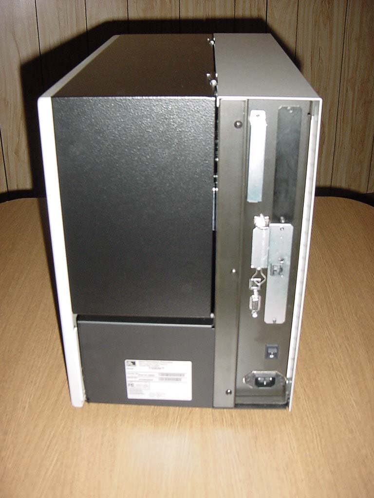
Click to zoom
Application Details
- Equipment Class
- DXX - Part 15 Low Power Communication Device Transmitter
- Date of Grant
- Oct 04, 2004
- Application Purpose
- Original Equipment
- Date of Application
- Oct 04, 2004
- Equipment Note
- RFID High Performance Printer
- Frequency Range
- 13.56000000 - 13.56000000
- Country
- United States
Documents & Files
Document Text
Text extracted from the exhibit documents filed with the FCC. Open a document above to read the original.
Users Manual
23063L-001 Rev. 1 6/7/2004RXiIIIPlus User Guide61 5 RFID Guidelines This chapter provides an overview of how RFID works and the ZPL commands used to create RFID labels. Contents Overview . . . . . . . . . . . . . . . . . . . . . . . . . . . . . . . . . . . . . . . . . . . . . . . . . . . . . . . . . . . . . 62 Transponder Placement . . . . . . . . . . . . . . . . . . . . . . . . . . . . . . . . . . . . . . . . . . . . . . . . . . 62 ZPL II Commands for RFID . . . . . . . . . . . . . . . . . . . . . . . . . . . . . . . . . . . . . . . . . . . . . . . 63 Sample of RFID Programming . . . . . . . . . . . . . . . . . . . . . . . . . . . . . . . . . . . . . . . . . . . . . 70 62RXiIIIPlus User Guide6/7/2004 23063L-001 Rev. 1 RFID Guidelines Overview Overview The R110XiIIIplus “smart” label printer-encoders serve as dynamic tools for both printing and encoding RFID labels, tickets, and tags. The printer encodes information on ultra-thin UHF RFID transponders embedded in “smart” labels. It then immediately verifies proper encoding and prints bar codes, graphics, and/or text on the label’s surface. For more information about RFID media, see RFID “Smart” Labels on page 16. Function of an encoded “smart” label depends on factors such as where the label is placed on an item as well as on the contents of the item (such as metals or liquids). Contact the supplier of your RFID transponders for assistance with these types of issues. Transponder Placement Communication between the “smart” label and the printer is established when the transponder lines up with the printer’s antenna. The optimal transponder position varies with the transponder size, its configuration, and the type of RFID IC chip used. Print quality may be affected by printing directly over the transponder. In particular, there is an area on each label immediately around the location of the IC chip where the printer may print with low quality. Design your printed label around the location of the chip in the type of approved “smart” label that you select. For the list of approved transponders and related placement specifications, go to http://www.rfid.zebra.com/r110.htm. Important • It is important to use transponders that have been specifically approved for use in this RFID printer. Failure to do so may result in the inability to read or write to the embedded RFID tags. As new transponders become commercially available, Zebra will evaluate them for compatibility with this printer. For the list of approved transponders, go to http://www.rfid.zebra.com/r110.htm. RFID Guidelines ZPL II Commands for RFID 23063L-001 Rev. 1 6/7/2004RXiIIIPlus User Guide63 ZPL II Commands for RFID Printing and encoding (writing) of “smart” labels is handled through the use of Zebra Programming Language (ZPL). Each transponder has memory that can be read from through ZPL commands, and most transponders have memory that can be written to. The printer divides the ZPL commands that it receives into two categories: RFID and non-RFID (such as the printing commands for bar codes or human-readable text). The RFID commands are executed first. ZPL commands also provide for exception handling, such as setting the number of read/write retries before declaring a transponder defective. For example, if an RFID transponder fails to program correctly or cannot be detected, the printer ejects it and prints the word “VOID” across the label. This process continues for the number of RFID tags specified by the ^RS command using the same data and format. The following pages provide the ZPL II commands that can be used for RFID applications. Important • If a parameter is designated as not applicable, any value entered for the parameter will be ignored, but the place holder for the field is required. 64RXiIIIPlus User Guide6/7/2004 23063L-001 Rev. 1 RFID Guidelines ^HV ^HV Host Verification Description This command is used to return data from specified fields, along with an optional ASCII header, to the host. It can be used with any field that has been assigned a number with the ^RT command. Format ^HV#,n,h The following table identifies the parameters for this format. ParametersDetails #= field number specified with another command The value assigned to this parameter should be the same as the one used in the ^RT command. Accepted values: 0 to 9999 Default value: 0 n= number of bytes to be returned Accepted values: 1 to 256 Default value: 64 h= headerHeader (in uppercase ASCII characters) to be returned with the data. Acceptable values: 0 to 3072 characters Default value: none RFID Guidelines ^RS 23063L-001 Rev. 1 6/7/2004RXiIIIPlus User Guide65 ^RS RFID Setup Description The ^RS command moves the RFID tag into the effective area for reading or writing or for possible error handling if there is an error. Format ^RSt,p,v,n,e The following table identifies the parameters for this format. Important • Use care when using this command in combination with ^RT (reading tag data). Problems can occur if the data read from the tag is going to be printed on the label. Any data read from the transponder must be positioned to be printed above the read/write position. Failure to do this will prevent read data from being printed on the label. ParametersDetails t=tag typeAccepted values: • 1 = Auto detect (automatically determine the tag type by querying the tag) Default value: 1 p= read/write position of the transponder in the vertical (Y axis) in dot rows from the top of the label Set to 0 (no movement) if the transponder is already in the effective area without moving the media. Accepted values: 0 to label length Default value: label length minus 8 dot rows v= length of void printout in vertical (Y axis) dot rows Default value: label length Accepted values: 0 to label length n= number of labels to try in case of read/encode failure Default value: 3 Accepted values: 1 to 10 (number of labels) e= error handlingIf an error persists after the specified number of labels are tried, perform this error hand…
Text truncated - open the document above for the full version.
Cover Letter(s)
Letter of Agency Date: August 27, 2004 American Telecommunications Certification Body, Inc. 6731 Whittier Avenue Suite C110 McLean, VA 22101 To Whom It May Concern: Please be advised that Zebra Technologies Corporation authorizes D.L.S. Electronic Systems, Inc. to act on our behalf, until otherwise notified, for applications submitted to American Telecommunications Certification Body, Inc. (ATCB). We certify that we are not subject to denial of federal benefits, that includes FCC benefits, pursuant to Section 5301 of the Anti-Drug Abuse ACT of 1988, U.S.C. 862. Further, no party, as defined in 47 CFR 1.2002(b), to the application is subject to denial of federal benefits, that includes FCC benefits. Thank you for your attention to this matter. Signatory, Arnom C. Rowe EMC ENGINEER EMC-001375-NE D.L.S. Electronic Systems, Inc. FCC Labeling Requirements and Information Date: August 27, 2004 American Telecommunications Certification Body, Inc. 6731 Whittier Avenue Suite C110 McLean, VA 22101 RE: FCC Labeling Requirements FCC ID: I28RFID-R110XI-02 The following label information is required by the FCC Rules and Regulations for certified devices. Also attached, please find marketing information required by the FCC Rules and Regulations. Thank you for your attention to these matters. Sincerely, Arnom C. Rowe EMC ENGINEER EMC-001375-NE D.L.S. Electronic Systems, Inc. Request for Confidentiality Date: August 27, 2004 American Telecommunications Certification Body, Inc. 6731 Whittier Avenue Suite C110 McLean, VA 22101 RE: Certification Application FCC ID: I28RFID-R110XI-02 Please be advised that the following information is to be held confidential and behalf of APPLICANT NAME: • Block Diagram • Schematics The application contains technical information which Zebra Technologies Corporation deems to be trade secrets and proprietary. If made public, the information might be used to the disadvantage of the applicant in the market place. Thank you for your attention to this matter. Signatory Arnom C. Rowe EMC ENGINEER EMC-001375-NE D.L.S. Electronic Systems, Inc. Modification Letter Date: August 27, 2004 American Telecommunications Certification Body, Inc. 6731 Whittier Avenue Suite C110 McLean, VA 22101 RE: Certification Application FCC ID: I28RFID-R110XI-02 Please be advised that the following information is a list of modifications that will be included in the production process for the above-referenced equipment. Change 1: There were no modifications made during testing. Change 2: Change 3: Change 4: Change 5: Change 6: Change 7: Change 8: Change 9 Change 10: Thank you for your attention to this matter. Signatory Arnom C. Rowe EMC ENGINEER EMC-001375-NE D.L.S. Electronic Systems, Inc. Manufacturer’s Letter Date: August 27, 2004 American Telecommunications Certification Body, Inc. 6731 Whittier Avenue Suite C110 McLean, VA 22101 RE: Certification Application FCC ID: I28RFID-R110XI-02 To Whom It May Concern: Please be advised that the manufacturer will ensure that the above-referenced model will be manufactured in accordance with the FCC Rules and Regulations. Thank you for your attention to this matter. Signatory Arnom C. Rowe EMC ENGINEER EMC-001375-NE D.L.S. Electronic Systems, Inc.
Cover Letter(s)
FCC ID: I28RFID-R110XI-02 D.L.S. ELECTRONIC SYSTEMS, INC. 1250 Peterson Drive Wheeling, Illinois 60090 FCC Authorization & Evaluation Division 7435 Oakland Mills Road Columbia, Maryland 21045-0429 Gentlemen: We are submitting for Zebra Technologies Corporation, Inc., a R110XiIII PlusTransmitter, Model Number 110XiIII, with a FCC ID: I28RFID-R110XI-02 for Certification. This unit has been tested and complies to Part 15, Subpart C. If there are any questions in regards to this application, please call D.L.S. Electronic Systems, Inc. at (847) 537 6400. Enclosed you will find a copy of our test report with the information and results of tests that is required under Part 15, Section 15.225. Thank you for your assistance in this matter. Sincerely, Arnom C. Rowe EMC-001375-NE DLS/sr
Cover Letter(s)
333 Corporate Woods Parkway Vernon Hills, Illinois 60061.3109 U.S.A. Telephone +1.847.634.6700 Facsimile +1.847.821.1795 www.zebra.com AUTHORIZATION FCC Authorization & Evaluation Division 7435 Oakland Mills Road Columbia, Maryland 21045-0429 Ladies and or Gentlemen: I appoint Brian J. Mattson or Arnom C. Rowe to act as agent in the preparation of applications under Part 15 of the Rules and Regulations of the Federal Communications Commission. I certify that the exhibits properly describe the device being submitted under this application and will implement any changes described in the test report. The following statement is required by the Federal Communications Commission: By checking yes, the applicant certifies that, in the case of an individual applicant, he or she is not subject to a denial of federal benefits, that includes FCC benefits, pursuant to Section 5301 of the Anti-Drug Abuse Act of 1988, 21 U.S.C. 853(a), or, in the case of an non-individual applicant (e.g. corporation, partnership or other unincorporated association), no party to the application is subject to a denial of federal benefits, that includes FCC benefits, pursuant to that section. __X___ YES _____ NO Dated this 27 th day of August 2004 Agency agreement expiration date: None By Mr. Charles A. Derrow Signature Printed Title Manager, Compliance Engineering Telephone 847.793.5719 Applicant Zebra Technologies Corporation
Cover Letter(s)
American Telecommunications Certification Body Inc. 6731 Whittier Ave, McLean, VA 22101 September 1, 2004 RE: FCC ID: I28RFID-R110XI-02_ATCB001643 Attention: Arnie Rowe I have a few comments on this Application. Please note that further comments may arise in response to answers provided to the questions below. 1. FYI – no action needed. Please note that as this is a device under the low power sections and operates at 13MHz, there is no need to provide MPE results as the device is categorically excluded. 2. Please note that there is a ferrite on what appears to be the antenna cable of the device (see internal photos). The cover letters state no modifications were performed so this appears to be a ferrite place on the device prior to testing. However, other internal photos do not to show this ferrite on the antenna cable (see internal photos on pages 4, 7, 10 and 11 of the disassembly of the main unit file name 10927 Zebra Internal Photos.pdf ). Please explain and please verify that the cable to which this ferrite is connected is part of the assembly process. Please note that this ferrite may also be on the grant notes if it is required for compliance. 3. Please provide a label on the product with the 2-condition statement as required by 15.19(a)(3). Please show where on the product this label will be placed. Alternately, please provide a reasonable explanation in accordance with 15.19(a)(5) that excludes this device from this requirement. 4. Please note that the antenna schematic shows J1 (con2) pins 1 and 2 go to the antenna. However, the main schematics indicate that the outputs go to pins 2 and 3 of CN2 (con2??). Please verify and/or explain the output connection to the antenna. 5. Please note that it is not clear from the photos how the antenna is a loop antenna as stated in the technical specs. Please explain. 6. Please explain why the full user manual has not been provided (i.e. is to file too large, etc?). 7. Please note that the device appears not in compliant to the FCC rules. Please note that section 15.209(c) states that “...However, the level of any unwanted emissions shall not exceed the level of the fundamental frequency.” Please note that as the limit for 15.225 is a QP limit, no QP reading of any spurious emission can exceed that of the fundamental. Please note that the corrected fundamental emissions at 13.56MHz is a QP reading of 27.4dBuV/m and the fundamental peak reading at 13.56MHz is 30.6dBuV/m. Please also note that spurious emissions readings shown on pages 48 and 50 of the test report show QP readings exceeding the fundamental. As such the device is non-compliant. Please note that the limit line on the plots of the fundamental clearly state 3 meters, and since the spurious radiated emissions data states testing was done at 3 meters, the indication is that the device is not compliant to 15.209(c). Please provide a test report showing compliance to the requirements of 15.209(c). 8. Please note that the technical specs for the device state that it operates at 68mW, but the measured field strength does not appear to agree with this statement. Please explain. Dennis Ward mailto:[email protected] The items indicated above must be submitted before processing can continue on the above referenced application. Failure to provide the requested information may result in application termination. Correspondence should be considered part of the permanent submission and may be viewed from the Internet after a Grant of Equipment Authorization is issued. z Page 2 September 1, 2004 Please do not respond to this correspondence using the email reply button. In order for your response to be processed expeditiously, you must submit your documents through the AmericanTCB.com website. Also, please note that partial responses increase processing time and should not be submitted. Any questions about the content of this correspondence should be directed to the sender.
Cover Letter(s)
FCC ID: I28RFID-R110XI-02_ATCB001643 Item 2: Please note that there is a ferrite on what appears to be the antenna cable of the device (see internal photos). The cover letters state no modifications were performed so this appears to be a ferrite place on the device prior to testing. However, other internal photos do not to show this ferrite on the antenna cable (see internal photos on pages 4, 7, 10 and 11 of the disassembly of the main unit file name 10927 Zebra Internal Photos pdf). Please explain and please verify that the cable to which this ferrite is connected is part of the assembly process. Please note that this ferrite may also be on the grant notes if it is required for compliance. The picture on page 4 showing what looks like ferrite is not a ferrite. This is a hole in the chassis where the red leads are exiting to another place in the Printer. Item 3: Please provide a label on the product with the 2-condition statement as required by 15.19(a)(3). Please show where on the product this label will be placed. Alternately, please provide a reasonable explanation in accordance with 15.19(a)(5) that excludes this device from this requirement. As stated in 15.19(a)(5), it is impracticable for Zebra to place the statement on the label because of the cost of changing their labeling process. The 2 part statement is placed inside the User’s Manual. Item4: Please note that the antenna schematic shows J1 (con2) pins 1 and 2 go to the antenna. However, the main schematics indicate that the outputs go to pins 2 and 3 of CN2 (con2??). Please verify and/or explain the output connection to the antenna. The outputs of the Antenna J1, Pins 1 and 2 (con1) go to the two pin connector CN1, CN1-1 and CN1-2, not CN2 the 10 pin connector used for the communications going to the printer as shown on Sheet 2 of the schematics. Item 5: Please note that it is not clear from the photos how the antenna is a loop antenna as stated in the technical specs. Please explain. The antenna is buried within the PCB and cannot be seen. See the enclosed pdf documentation. Item 6: Please explain why the full user manual has not been provided (i.e. is to file too large, etc?). The file size of the user’s manual is 3.3 megs which is to large to be submit as one exhibit. It can be broken down to 2 parts, but the FCC only wants to see in the Table of Contents where the required materials is located and the actual pages. Item 7: Please note that the device appears not in compliant to the FCC rules. Please note that section 15.209(c) states that “ However, the level of any unwanted emissions shall not exceed the level of the fundamental frequency.” Please note that as the limit for 15.225 is a QP limit, no QP reading of any spurious emission can exceed that of the fundamental. Please note that the corrected fundamental emissions at 13.56MHz is a QP reading of 27.4dBuV/m and the fundamental peak reading at 13.56MHz is 30.6dBuV/m. Please also note that spurious emissions readings shown on pages 48 and 50 of the test report show QP readings exceeding the fundamental. As such the device is non-compliant. Please note that the limit line on the plots of the fundamental clearly state 3 meters, and since the spurious radiated emissions data states testing was done at 3 meters, the indication is that the device is not compliant to 15.209(c). Please provide a test report showing compliance to the requirements of 15.209(c). See test reports 10927 and 10928 showing the updated test data taken on September 7, 2004 with the harmonics being lower then the fundamental, as stated in 15.209(c). Item 8: Please note that the technical specs for the device state that it operates at 68mW, but the measured field strength does not appear to agree with this statement. Please explain. The 68 mW answer was indicating the power going to the antenna. This answer is wrong. The new data taken on September 7 th yields a field strength measurement of 34.9 dBuV at 3 meters. Far Field = 370 ohms / 4π = 29.46 34.9 dBuV = .055 V/m .055 V/m * 3 meters = .165 .165 2 = .027225 .027225 / 29.46 = .924 mW
Cover Letter(s)
From: Arnie Rowe [mailto:[email protected]] Sent: Wednesday, October 06, 2004 11:08 AM To: dward ATCB Subject: FCC ID: I28RFID-R110XI-02 Hi Dennis 1. At what distance was the 13MHz carrier signal measured? Could not tell from report or photos. (I see a lot of reference to Canadian Standards - but we require all measurements below 30MHz to be measured preferably at 3 meters but no closer than 1 meter.) If done closer than 3 meters, why? Response - Tests were run at 3 meters. 2. What type of antenna was used for the 13 MHz measurements? Response EMCO Active Loop Antenna Model Number: 6502 Serial Number: 1027 Calibration Date: July 19, 2004 Dennis, I will update my test reports so this doesn't happen again. Jason, at our open field will make sure the charts will state the distance that the antenna is from the EUT. However, I have Stryker at TCB that was done at 13 MHZ, so it will need to show the test distance at 3 meters and the above test antenna. Arnie
External Photos
Company: Zebra Technologies Product: R110XiIII Plus FCC ID#: I28RFID-R110XI-02 IC ID#: 3798A-R110XI02 Date: 7/10/2004 Photo Description: Front of EuT Company: Zebra Technologies Product: R110XiIII Plus FCC ID#: I28RFID-R110XI-02 IC ID#: 3798A-R110XI02 Date: 7/10/2004 Photo Description: Left Side of EuT Company: Zebra Technologies Product: R110XiIII Plus FCC ID#: I28RFID-R110XI-02 IC ID#: 3798A-R110XI02 Date: 7/10/2004 Photo Description: Back Side of EuT Company: Zebra Technologies Product: R110XiIII Plus FCC ID#: I28RFID-R110XI-02 IC ID#: 3798A-R110XI02 Date: 7/10/2004 Photo Description: Right Side of EuT
ID Label/Location Info
333 Corporate Woods Parkway Vernon Hills, IL 60061 Zebra Technologies Corporation Config. No. Serial No. Model MADE IN U.S.A. XiIII110 FOR HOME, OFFICE, COMMERCIAL, OR INDUSTRIAL USE Tested To Comply With FCC Standards 90-264 VAC (V ca) 4A/300W MAX 47-63 Hz FCC ID: I28RFID-R110XI-02 CUS LISTED 17U5 I.T.E. This Class B digital apparatus complies with Canadian ICES-003 0977 110XiIII™ Canadian ID: 3798A-R110XI02
Internal Photos
Company: Zebra Technologies Product: R110XiIII Plus FCC ID#: I28RFID-R110XI-02 IC ID#: 3798A-R110XI02 Date: 7/10/2004 Photo Description: Right Side of EuT Company: Zebra Technologies Product: R110XiIII Plus FCC ID#: I28RFID-R110XI-02 IC ID#: 3798A-R110XI02 Date: 7/10/2004 Photo Description: Right Side of EuT Door Open Company: Zebra Technologies Product: R110XiIII Plus FCC ID#: I28RFID-R110XI-02 IC ID#: 3798A-R110XI02 Date: 7/10/2004 Photo Description: Front Side of EuT Door Open with Antenna Placement Company: Zebra Technologies Product: R110XiIII Plus FCC ID#: I28RFID-R110XI-02 IC ID#: 3798A-R110XI02 Date: 7/10/2004 Photo Description: Transmit Antenna Placement Company: Zebra Technologies Product: R110XiIII Plus FCC ID#: I28RFID-R110XI-02 IC ID#: 3798A-R110XI02 Date: 7/10/2004 Photo Description: Left Side of EuT, Cover Removed Company: Zebra Technologies Product: R110XiIII Plus FCC ID#: I28RFID-R110XI-02 IC ID#: 3798A-R110XI02 Date: 7/10/2004 Photo Description: Reader Board Placement in EuT Company: Zebra Technologies Product: R110XiIII Plus FCC ID#: I28RFID-R110XI-02 IC ID#: 3798A-R110XI02 Date: 7/10/2004 Photo Description: Reader Board Assembly, Power Filter Board and Antenna Assembly Connected Company: Zebra Technologies Product: R110XiIII Plus FCC ID#: I28RFID-R110XI-02 IC ID#: 3798A-R110XI02 Date: 7/10/2004 Photo Description: Component Side of Filter Board Company: Zebra Technologies Product: R110XiIII Plus FCC ID#: I28RFID-R110XI-02 IC ID#: 3798A-R110XI02 Date: 7/10/2004 Photo Description: Trace Side of Filter Board Company: Zebra Technologies Product: R110XiIII Plus FCC ID#: I28RFID-R110XI-02 IC ID#: 3798A-R110XI02 Date: 7/10/2004 Photo Description: Top Side of Antenna Company: Zebra Technologies Product: R110XiIII Plus FCC ID#: I28RFID-R110XI-02 IC ID#: 3798A-R110XI02 Date: 7/10/2004 Photo Description: Bottom Side of Antenna Company: Zebra Technologies Product: R110XiIII Plus FCC ID#: I28RFID-R110XI-02 IC ID#: 3798A-R110XI02 Date: 7/10/2004 Photo Description: Component Side of Reader Board Company: Zebra Technologies Product: R110XiIII Plus FCC ID#: I28RFID-R110XI-02 IC ID#: 3798A-R110XI02 Date: 7/10/2004 Photo Description: Trace Side of Reader PCB
Test Report
Company: Zebra Technologies Corporation Model Tested: 110XiIII Report Number: 10928 1250 Peterson Dr., Wheeling, IL 60090 LOW POWER LICENCE-EXEMPT RADIO COMMUNICATION DEVICES (ALL FREQUENCY BANDS) RADIO STANDARDS SPECIFICATION RSS-210, ISSUE 5 NOVEMBER 2001 THE FOLLOWING ''MEETS'' THE ABOVE TEST SPECIFICATION Formal Name: R110XiIII Plus Kind of Equipment: Thermal Transfer on demand bar code printer Test Configuration: RFID - HF 13.56 MHz (Tested at 120 vac, 60 Hz) Model Number(s): 110XiIII Model(s) Tested: 110XiIII Serial Number(s): 91C04220027 Date of Tests: July 8, 9, 27 & September 7, 2004 Test Conducted For: Zebra Technologies Corporation 333 Corporate Woods Parkway Vernon Hills, Illinois 60061 NOTICE: “This report must not be used by the client to claim product endorsement by NVLAP or any agency of the U.S. Government”. Please see the "Additional Description of Equipment Under Test" page listed inside of this report. This report must not be reproduced (except in full), without the approval of D.L.S. Electronic Systems. Page - 1 - Company: Zebra Technologies Corporation Model Tested: 110XiIII Report Number: 10928 1250 Peterson Dr., Wheeling, IL 60090 SIGNATURE PAGE Report By: Arnom C. Rowe Test Engineer EMC-001375-NE Reviewed By: William Stumpf OATS Manager Approved By: Brian Mattson General Manager Company Official: Zebra Technologies Corporation Page - 2 - 1250 Peterson Dr., Wheeling, IL 60090 Company: Zebra Technologies Corporation Model Tested: 110XiIII Report Number: 10928 Page -3- 1250 Peterson Dr., Wheeling, IL 60090 Company: Zebra Technologies Corporation Model Tested: 110XiIII Report Number: 10928 Page -4- 1250 Peterson Dr., Wheeling, IL 60090 Company: Zebra Technologies Corporation Model Tested: 110XiIII Report Number: 10928 Page -5- 1250 Peterson Dr., Wheeling, IL 60090 Company: Zebra Technologies Corporation Model Tested: 110XiIII Report Number: 10928 Page -6- 1250 Peterson Dr., Wheeling, IL 60090 Company: Zebra Technologies Corporation Model Tested: 110XiIII Report Number: 10928 Page -7- 1250 Peterson Dr., Wheeling, IL 60090 Company: Zebra Technologies Corporation Model Tested: 110XiIII Report Number: 10928 Page -8- 1250 Peterson Dr., Wheeling, IL 60090 Company: Zebra Technologies Corporation Model Tested: 110XiIII Report Number: 10928 Page -9- 1250 Peterson Dr., Wheeling, IL 60090 Company: Zebra Technologies Corporation Model Tested: 110XiIII Report Number: 10928 Page -10- 1250 Peterson Dr., Wheeling, IL 60090 Company: Zebra Technologies Corporation Model Tested: 110XiIII Report Number: 10928 Page -11- 1250 Peterson Dr., Wheeling, IL 60090 Company: Zebra Technologies Corporation Model Tested: 110XiIII Report Number: 10928 Page -12- 1250 Peterson Dr., Wheeling, IL 60090 Company: Zebra Technologies Corporation Model Tested: 110XiIII Report Number: 10928 TABLE OF CONTENTS i. Cover Page...........................................................................................................................................1 ii. Signature Page.....................................................................................................................................2 iii. NVLAP Certificate of Accreditation...............................................................................................3 iv. NVLAP Scope of Accreditation......................................................................................................4 v. Table of Contents...............................................................................................................................13 1.0 Summary of Test Report................................................................................................................14 2.0 Introduction....................................................................................................................................14 3.0 Test Set-Up....................................................................................................................................14 4.0 Test Equipment..............................................................................................................................15 5.0 Description of Test Sample............................................................................................................16 6.0 Additional Description of Test Sample..........................................................................................18 7.0 Photo Information and Test Set-Up...............................................................................................19 8.0 Radiated Photos Taken During Testing.........................................................................................20 8.0 Conducted Photos Taken During Testing......................................................................................22 9.0 Results of Tests..............................................................................................................................23 10.0 Conclusion.....................................................................................................................................23 Appendix A – Electric Field Radiated Emissions Test..............................................................................24 1.0 Supply Voltage – (Section 5.2)......................................................................................................25 2.0 Types of Modulation – (Section 5.4).............................................................................................25 3.0 Emission Bandwidth – (Section 5.9).............................................................................................25 3.0 Graphs Taken of the Emission Bandwidth....................................................................................26 4.0 Frequency Range – (Section 6.2)...................................................................................................28 5.0 DC Power Consumption Method – (Section 12)....................…
Text truncated - open the document above for the full version.
Contact Information
Applicant
Jay Cadiz(Sr. Manager, Regulatory)
Technical Contact
DLS Electronic Systems, Inc.Arnom Rowe
[email protected]847-537-6400
1250 Peterson Drive · Wheeling, Illinois · United States
Test Firm
DLS Electronic Systems, Inc.William Stumpf
Technical Specifications
| # | Rule Parts | Frequency Range | Power Output | Tolerance |
|---|---|---|---|---|
| 1 | 15C | 13.56 MHz - 13.56 MHz | - | 0.0100000000 % |
Other Applications from Zebra Technologies Corporation
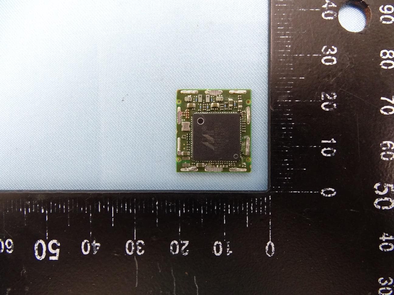
I28-WYSBHVDXP
May 19, 2021WLAN/BTLE module
Equipment Class
DTS - Digital Transmission System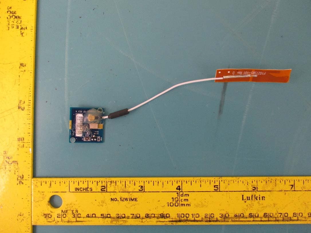
I28-EYSNSNZWWZ1
May 04, 2021BT5 Radio Module
Equipment Class
DTS - Digital Transmission System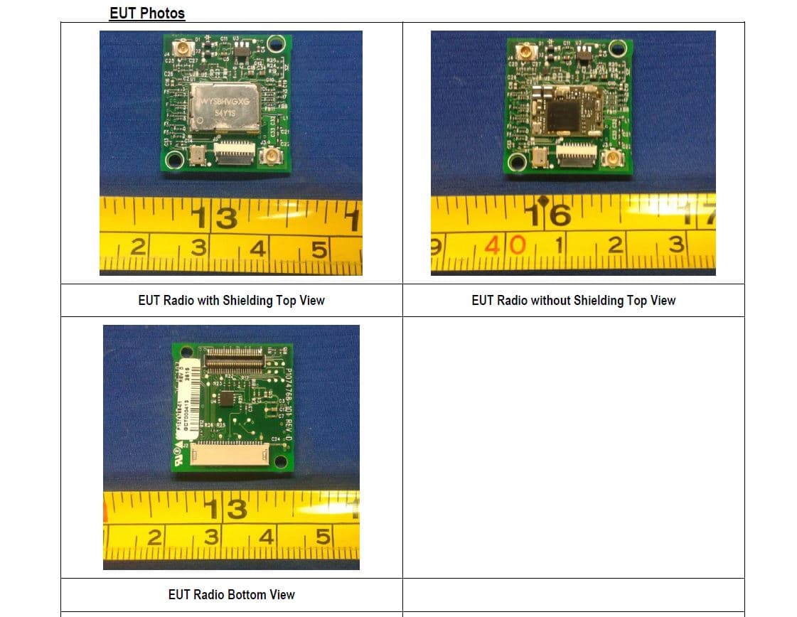
I28MD-FXLAN11AC
Nov 22, 2015Wireless 802.11ac + Bluetooth Module
Equipment Class
DSS - Part 15 Spread Spectrum Transmitter
I28MD-ZBRBLE
Nov 19, 2015Bluetooth Low Energy Module
Equipment Class
DTS - Digital Transmission System
I28MD-ZBR7BTLE
Jan 19, 2015Bluetooth 4.0 LE Module
Equipment Class
DSS - Part 15 Spread Spectrum Transmitter