I28RFID-R402-2Thermal Printer with RFID Capability
Zebra Technologies Corporation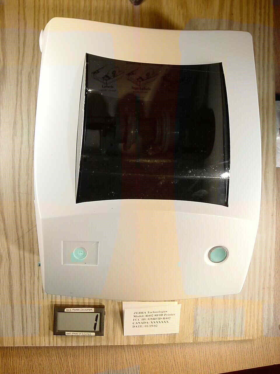
Click to zoom
Application Details
- Equipment Class
- DXX - Part 15 Low Power Communication Device Transmitter
- Date of Grant
- Apr 23, 2002
- Application Purpose
- Original Equipment
- Date of Application
- Apr 23, 2002
- Equipment Note
- Thermal Printer with RFID Capability
- Frequency Range
- 13.56000000 - 13.56000000
- Country
- United States
Documents & Files
Document Text
Text extracted from the exhibit documents filed with the FCC. Open a document above to read the original.
Users Manual
R402 Stripe Series Thermal Printer ® User s Guide ' Contents Introduction Hello! . . . . . . . . . . . . . . . . . . . . . . . . . . . . . . . . . . . . . . . . . . . . . . . . . . . . . 1 What’s in the Box?. . . . . . . . . . . . . . . . . . . . . . . . . . . . . . . . . . . . . . . . . . . 2 Inspecting the Printer . . . . . . . . . . . . . . . . . . . . . . . . . . . . . . . . . . . . . . . . . 3 Opening the printer . . . . . . . . . . . . . . . . . . . . . . . . . . . . . . . . . . . . . . . 3 Closing the printer . . . . . . . . . . . . . . . . . . . . . . . . . . . . . . . . . . . . . . . . 5 Reporting Damage. . . . . . . . . . . . . . . . . . . . . . . . . . . . . . . . . . . . . . . . 6 Getting Started Modes of Printing. . . . . . . . . . . . . . . . . . . . . . . . . . . . . . . . . . . . . . . . . . . . 7 Attaching Power Supply . . . . . . . . . . . . . . . . . . . . . . . . . . . . . . . . . . . . . . 8 Loading Roll Media . . . . . . . . . . . . . . . . . . . . . . . . . . . . . . . . . . . . . . . . . . 9 Placing the Roll in the Media Compartment . . . . . . . . . . . . . . . . . . . . 9 Adjusting the Guides . . . . . . . . . . . . . . . . . . . . . . . . . . . . . . . . . . . . . 10 Loading Ribbon . . . . . . . . . . . . . . . . . . . . . . . . . . . . . . . . . . . . . . . . . . . . 11 Install the Ribbon Supply Roll . . . . . . . . . . . . . . . . . . . . . . . . . . . . . 11 Install the Take-Up Core . . . . . . . . . . . . . . . . . . . . . . . . . . . . . . . . . . 11 Attach and Tighten the Ribbon . . . . . . . . . . . . . . . . . . . . . . . . . . . . . 12 Auto Calibration. . . . . . . . . . . . . . . . . . . . . . . . . . . . . . . . . . . . . . . . . . . . 13 Operator Controls . . . . . . . . . . . . . . . . . . . . . . . . . . . . . . . . . . . . . . . . . . 14 Power Switch . . . . . . . . . . . . . . . . . . . . . . . . . . . . . . . . . . . . . . . . . . 14 Feed Button . . . . . . . . . . . . . . . . . . . . . . . . . . . . . . . . . . . . . . . . . . . 14 Status Light . . . . . . . . . . . . . . . . . . . . . . . . . . . . . . . . . . . . . . . . . . . . 14 Printing a Test Label . . . . . . . . . . . . . . . . . . . . . . . . . . . . . . . . . . . . . . . . 15 Hooking Up the Printer and Computer . . . . . . . . . . . . . . . . . . . . . . . . . . 15 Parallel Interface Requirements . . . . . . . . . . . . . . . . . . . . . . . . . . . . 16 Interface Cable Requirements . . . . . . . . . . . . . . . . . . . . . . . . . . . . . . 16 Communicating with the Printer . . . . . . . . . . . . . . . . . . . . . . . . . . . . . . . 17 Adjusting the Print Width . . . . . . . . . . . . . . . . . . . . . . . . . . . . . . . . . . . 17 Adjusting the Print Darkness. . . . . . . . . . . . . . . . . . . . . . . . . . . . . . . . 17 Adjusting the Print Speed . . . . . . . . . . . . . . . . . . . . . . . . . . . . . . . . . . . 17 Operation & Options Thermal Printing . . . . . . . . . . . . . . . . . . . . . . . . . . . . . . . . . . . . . . . . . . . 19 Replacing Supplies. . . . . . . . . . . . . . . . . . . . . . . . . . . . . . . . . . . . . . . . . . 20 Adding a New Transfer Ribbon . . . . . . . . . . . . . . . . . . . . . . . . . . . . 20 Replacing a Partially Used Transfer Ribbon . . . . . . . . . . . . . . . . . . . 20 Printing in Peel-Mode . . . . . . . . . . . . . . . . . . . . . . . . . . . . . . . . . . . . . . . 21 Printing on Fan-Fold Media . . . . . . . . . . . . . . . . . . . . . . . . . . . . . . . . . . . 22 RFID Guidelines Supported Transponders . . . . . . . . . . . . . . . . . . . . . . . . . . . . . . . . . . . . . 24 Tag-it Transponders. . . . . . . . . . . . . . . . . . . . . . . . . . . . . . . . . . . . . . 24 I•Code Transponders. . . . . . . . . . . . . . . . . . . . . . . . . . . . . . . . . . . . . 25 Picotag Transponders . . . . . . . . . . . . . . . . . . . . . . . . . . . . . . . . . . . . 26 ISO-15693 Transponders. . . . . . . . . . . . . . . . . . . . . . . . . . . . . . . . . . 27 ZPL II Commands for RFID . . . . . . . . . . . . . . . . . . . . . . . . . . . . . . . . . . 28 ^WT – Write Tag. . . . . . . . . . . . . . . . . . . . . . . . . . . . . . . . . . . . . . . . 28 ^RT – Read Tag. . . . . . . . . . . . . . . . . . . . . . . . . . . . . . . . . . . . . . . . . 29 ^RS – RFID Setup . . . . . . . . . . . . . . . . . . . . . . . . . . . . . . . . . . . . . . . 31 ^RI – RFID Get Tag Unique ID . . . . . . . . . . . . . . . . . . . . . . . . . . . . 31 Sample of RFID Programming . . . . . . . . . . . . . . . . . . . . . . . . . . . . . 32 Maintenance Cleaning . . . . . . . . . . . . . . . . . . . . . . . . . . . . . . . . . . . . . . . . . . . . . . . . . . 35 Lubrication . . . . . . . . . . . . . . . . . . . . . . . . . . . . . . . . . . . . . . . . . . . . . . . . 35 Replacing the Print Head . . . . . . . . . . . . . . . . . . . . . . . . . . . . . . . . . . . . . 36 Removal. . . . . . . . . . . . . . . . . . . . . . . . . . . . . . . . . . . . . . . . . . . . . . . 36 Assembly . . . . . . . . . . . . . . . . . . . . . . . . . . . . . . . . . . . . . . . . . . . . . . 37 Troubleshooting Resolutions. . . . . . . . . . . . . . . . . . . . . . . . . . . . . . . . . . . . . . . . . . . . . . . . 39 Print Quality Problems. . . . . . . . . . . . . . . . . . . . . . . . . . . . . . . . . . . . . . . 42 RFID Symptoms . . . . . . . . . . . . . . . . . . . . . . . . . . . . . . . . . . . . . . . . . . . 44 RFID tags generally not programmed . . . . . . . . . . . . . . . . . . . . . . . . 44 VOID messages are printed across media. . . . . . . . . . . . . . . . . . . . . 44 Nothing is printed. . . . . . . . . . . . . . . . . . . . . . . . . . . . . . . . . . . . . . . . 44 Manual Calibration . . . . . . . . . . . . . . . . . . . . . . . . . . . . . . . . . . . . . . . . 45 Troubleshooting Tests Printing a Configuration Label . . . . . . . . . . . . . . . . . . . . . . . . . . . . . 46 Recalibration . . . . . . . . . . . . . . . . . . . . . . . . . . . . . . . . . . …
Text truncated - open the document above for the full version.
Users Manual
Closing the printer Hold the top cover and press the cover lock to release. Lower the top cover. The ribbon carriage automatically folds up into place. Press down until the cover snaps closed. Reporting Damage If you discover damage or missing parts: ■ Immediately notify and file a damage report with the shipping company. Zebra Technologies Corporation is not responsible for any damage incurred during shipment of the printer and will not cover the repair of this damage under its warranty policy. ■ Keep the carton and all packing material for inspection. ■ Notify the authorized reseller Getting Started This section describes how to set up your printer for the first time and use the most common operating procedures for loading media in tear-off mode and loading ribbon. Modes of Printing You can operate this printer in two different modes: tear-off or peel-off. ■ Standard tear-off mode allows you to tear off each label (or a strip of labels) after it is printed. ■ In optional peel-off mode, the backing material is peeled away from the label as it is printed. After this label is removed, the next one is printed. The printer typically uses roll media, but you can use fan-fold media as well. For procedures to use optional modes and features, refer to the Using Options section. Attaching Power Supply Check the power supply to make certain it is appropriate for your input voltage. Warning: Use the Zebra-supplied power supply that came with your printer. Never operate the printer and power supply in an area where they can get wet. Serious personal injury could result! 1. Make sure the power switch is in the off position (down). 2. The DC power supply has a barrel connector on one end that must be inserted into the power supply receptacle on the back of the printer. 3. Insert the separate AC power cord into the power supply. 4. Plug the other end of the cord into an appropriate AC electrical outlet. Plug Varies b Countr AC Powe r Cord Power Supply Power Switch Power Supply Receptacle Barrel Connector Loading Roll Media When you load media, you must place the roll on the media hangers and then adjust the media guides. Placing the Roll in the Media Compartment Whether your roll media is inside or outside wound you load it into the printer the same way. 1. Open the printer. Remember that you need to pull the release levers toward the front of the printer. 2. Remove the outside length of media. During shipment, the roll may become dirty when handled or dusty when stored. Removing the outside length avoids dragging adhesive or dirty media between the print Head and platen. 3. Separate and hold open the media hangers. 4. Orient the media roll so that its printing surface will be up as it passes over the platen. 5. Lower the roll between the hangers and close them onto the core. Adjusting the Guides The adjustable guides direct the media toward the platen and print Head. 1. Open the media guides by turning the guide adjuster knob to the rear. 2. Thread the media through the guides. 3. Close the media guides by turning the guide adjuster knob to the front. They should just touch, but not restrict, the edges of the media. 4. Unless you need to load ribbon, close the top cover. Remember that you need to release the cover lock, lower the top cover, and press down until the latches snap into place. Loading Ribbon You must use thermal transfer media (accepts wax and/or resin transferred off a ribbon) when you use a ribbon. When loading ribbon, you install the supply and take-up rolls, then tighten the ribbon on the carriage. Install the Ribbon Supply Roll Before following these steps, prepare the ribbon by removing its wrapping and pulling its adhesive strip free. 1. Thread the ribbon through the carriage. 2. Press the right side onto the supply hub. 3. Align the notches on the left side and mount onto the spokes of the left hub. Install the Take-Up Core 1. Press the right side onto the take-up hub. 2. Align the notches on the left side and mount onto the spokes of the left hub. Attach and Tighten the Ribbon You must align the ribbon so that it will be taken straight onto the core. 1. Attach the ribbon to the take up core. Use the adhesive strip on new rolls; otherwise, use tape. 2. Turn the ribbon take-up gear counter-clockwise (top moves toward rear) to remove slack from the ribbon. 3. Close the top cover. Remember that you need to release the cover lock, lower the top cover, and press down until the latches snap into place. Auto Calibration NOTE:If you are using pre-printed labels, pre-printed label backing, or continuous media, see “Manual Calibration” on page . An auto calibration is performed when the printer is turned on (if media is loaded) or after a media error is cleared. When it is auto calibrating, the printer sets the sensor levels for, and determines the length of, the label you are using. If the status light flashes red, refer to “Manual Calibration” on page .
Users Manual
Operator Controls Power Switch Pressupto turnONordownto turnOFFthe printer. CAUTION: The power should be turned off before connecting or disconnecting the communications and power cables. Feed Button Forces the printer to feed one blank label. Takes the printer out of a “pause” condition. (The printer is put into “pause” by either a ZPL II command or an error condition.) See “What the Status Light is Telling You” on page . Used for printer setup and status (see “Feed Button Modes” on page ). Status Light Functions as a printer operational indicator (see “What the Status Light is Telling You” on page ). Printing a Test Label Before you connect the printer to your computer, make sure that the printer is in proper working order. You can do this by printing a configuration label 1. Make sure the media is properly loaded and the top cover of the printer is closed. Then, turn the printer power on if you have not already done so. 2. When the status light is solid green, press and hold the feed button until the status light flashes once. 3. Release the feed button. A configuration label will print. If you cannot get this label to print, refer to Troubleshooting. Hooking Up the Printer and Computer This printer comes with a bidirectional parallel data interface. You must supply the required interface cable for your application. CAUTIONS:Keep the power switch in the OFF position when attaching the interface cable. The power supply barrel connector must be inserted into the power supply receptacle on the back of the printer before connecting or disconnecting the com - munications cables. This printer complies with FCC “Rules and Regula - tions,” Part 15, for Class B Equipment, using fully shielded six-foot data cables. Use of longer cables or unshielded cables may increase radiated emissions above the Class B limits. Parallel Interface Requirements The required cable (IEEE 1284-compliant is recommended) must have a standard 36-pin parallel connector on one end, which is plugged into the parallel port located on the back of the printer. The other end of the parallel interface cable connects to the printer connector at the host computer. For pinout information, refer to page . Interface Cable Requirements Data cables must be of fully shielded construction and fitted with metal or metalized connector shells. Shielded cables and connectors are required to prevent radiation and reception of electrical noise. To minimize electrical noise pickup in the cable: Keep data cables as short as possible (6’ [1.83 m] recommended). Do not tightly bundle the data cables with power cords. Do not tie the data cables to power wire conduits. Communicating with the Printer When using the parallel port, typically there is no setup is required once the cable is plugged in. If you should encounter any problems, consult the user’s guide that came with your computer. Adjusting the Print Width Print width must be calibrated when: ■ You are using the printer for the first time. ■ There is a change in the width of the media. Print width may be set by way of the five-flash sequence in “Feed Button Modes” (see page ) or refer to the Print Width (^PW) command (consult your ZPL II Programming Guide). Adjusting the Print Darkness The relative darkness setting is controlled by either the six-flash sequence in “Feed Button Modes” (see page ) or the Set Darkness (~SD) ZPL II command (follow the instructions in the ZPL II Programming Guide). Adjusting the Print Speed Print quality is affected by print speed and the media you are using. Only by experimenting will you find the optimal mix for your application. If you find that the print speed needs to be adjusted, refer to the Print Rate (^PR) command in the ZPL II Programming Guide. Operation & Options This section helps you get the most from your printer. You must use programming to control many of the printer’s functions. For example, the ~JL command controls label length. For detailed information about creating labels using ZPL II, refer to the ZPL II Programming Guide or visit our web site at www.zebra.com. To improve print quality, changing both print speed and density may be required to achieve the desired results. Your application’s printer driver provides control of the speed and heat (density). Thermal Printing The print head becomes hot while printing. To protect from damaging the print head and risk of personal injury, avoid touching the print head. Use only the cleaning pen to perform maintenance. The discharge of electrostatic energy that accumulates on the surface of the human body or other surfaces can damage or destroy the print head or electronic components used in this device. You must observe static-safe procedures when working with the print head or the electronic components under the top cover. You must use the correct media for the type of printing you require. When printing without a ribbon, you must use direct thermal media. When using ribbon, you must use thermal transfer media. The printer’s ribbon sensor detects motion of the supply spindle. Replacing Supplies If labels or ribbon run out while printing, leave the printer power on while reloading (data loss results if you turn off the printer). The printer automatically restarts after you load a new label or ribbon roll. Always use high quality, approved labels, tags and ribbons. If adhesive backed labels are used that don’t lay flat on the backing liner, the exposed edges may stick to the label guides and rollers inside the printer, causing the label to peel off from the liner and jam the printer. Permanent damage to the print head may result if a non-approved ribbon is used as it may be wound incorrectly for the printer or contain chemicals corrosive to the print head. Approved supplies can be ordered from your dealer. Adding a New Transfer Ribbon If ribbon runs out in the middle of a print job, the indicator lights orange and the printer waits for you to add a fresh roll. 1. Keep the power on as you change ri…
Text truncated - open the document above for the full version.
Users Manual
Contents Introduction Hello! . . . . . . . . . . . . . . . . . . . . . . . . . . . . . . . . . . . . . . . . . . . . . . . . . . . . . 1 What’s in the Box?. . . . . . . . . . . . . . . . . . . . . . . . . . . . . . . . . . . . . . . . . . . 2 Inspecting the Printer . . . . . . . . . . . . . . . . . . . . . . . . . . . . . . . . . . . . . . . . . 3 Opening the printer . . . . . . . . . . . . . . . . . . . . . . . . . . . . . . . . . . . . . . . 3 Closing the printer . . . . . . . . . . . . . . . . . . . . . . . . . . . . . . . . . . . . . . . . 5 Reporting Damage. . . . . . . . . . . . . . . . . . . . . . . . . . . . . . . . . . . . . . . . 6 Getting Started Modes of Printing. . . . . . . . . . . . . . . . . . . . . . . . . . . . . . . . . . . . . . . . . . . . 7 Attaching Power Supply . . . . . . . . . . . . . . . . . . . . . . . . . . . . . . . . . . . . . . 8 Loading Roll Media . . . . . . . . . . . . . . . . . . . . . . . . . . . . . . . . . . . . . . . . . . 9 Placing the Roll in the Media Compartment . . . . . . . . . . . . . . . . . . . . 9 Adjusting the Guides . . . . . . . . . . . . . . . . . . . . . . . . . . . . . . . . . . . . . 10 Loading Ribbon . . . . . . . . . . . . . . . . . . . . . . . . . . . . . . . . . . . . . . . . . . . . 11 Install the Ribbon Supply Roll . . . . . . . . . . . . . . . . . . . . . . . . . . . . . 11 Install the Take-Up Core . . . . . . . . . . . . . . . . . . . . . . . . . . . . . . . . . . 11 Attach and Tighten the Ribbon . . . . . . . . . . . . . . . . . . . . . . . . . . . . . 12 Auto Calibration. . . . . . . . . . . . . . . . . . . . . . . . . . . . . . . . . . . . . . . . . . . . 13 Operator Controls . . . . . . . . . . . . . . . . . . . . . . . . . . . . . . . . . . . . . . . . . . 14 Power Switch . . . . . . . . . . . . . . . . . . . . . . . . . . . . . . . . . . . . . . . . . . 14 Feed Button . . . . . . . . . . . . . . . . . . . . . . . . . . . . . . . . . . . . . . . . . . . 14 Status Light . . . . . . . . . . . . . . . . . . . . . . . . . . . . . . . . . . . . . . . . . . . . 14 Printing a Test Label . . . . . . . . . . . . . . . . . . . . . . . . . . . . . . . . . . . . . . . . 15 Hooking Up the Printer and Computer . . . . . . . . . . . . . . . . . . . . . . . . . . 15 Parallel Interface Requirements . . . . . . . . . . . . . . . . . . . . . . . . . . . . 16 Interface Cable Requirements . . . . . . . . . . . . . . . . . . . . . . . . . . . . . . 16 Communicating with the Printer . . . . . . . . . . . . . . . . . . . . . . . . . . . . . . . 17 Adjusting the Print Width . . . . . . . . . . . . . . . . . . . . . . . . . . . . . . . . . . . 17 Adjusting the Print Darkness. . . . . . . . . . . . . . . . . . . . . . . . . . . . . . . . 17 Adjusting the Print Speed . . . . . . . . . . . . . . . . . . . . . . . . . . . . . . . . . . . 17 Operation & Options Thermal Printing . . . . . . . . . . . . . . . . . . . . . . . . . . . . . . . . . . . . . . . . . . . 19 Replacing Supplies. . . . . . . . . . . . . . . . . . . . . . . . . . . . . . . . . . . . . . . . . . 20 Adding a New Transfer Ribbon . . . . . . . . . . . . . . . . . . . . . . . . . . . . 20 Reporting Damage If you discover damage or missing parts: ■ Immediately notify and file a damage report with the shipping company. Zebra Technologies Corporation is not responsible for any damage incurred during shipment of the printer and will not cover the repair of this damage under its warranty policy. ■ Keep the carton and all packing material for inspection. ■ Notify the authorized reseller
Cover Letter(s)
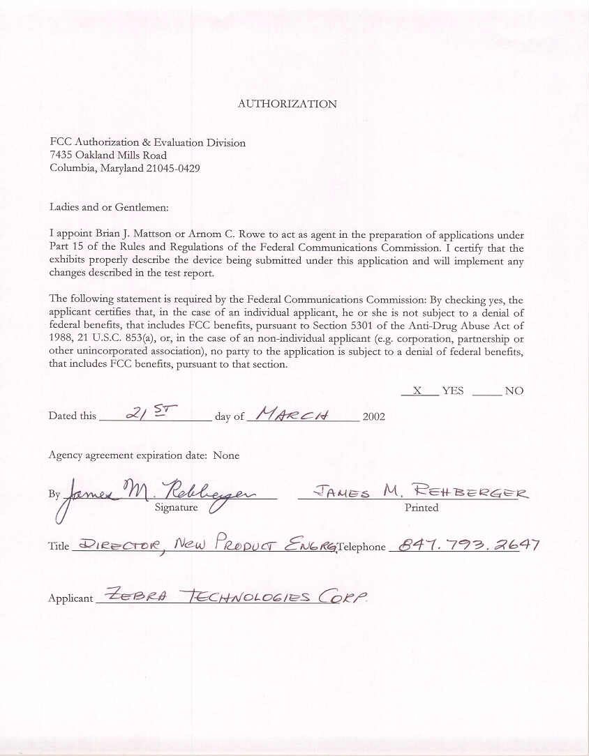
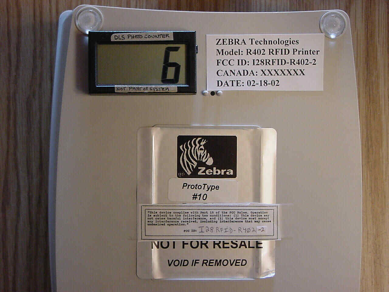
Letter of Agency Date: April 2, 2002 American Telecommunications Certification Body, Inc. 6731 Whittier Avenue Suite C110 McLean, VA 22101 To Whom It May Concern: Please be advised that Zebra Technologies Corporation authorizes D.L.S. Electronic Systems, Inc. to act on our behalf, until otherwise notified, for applications submitted to American Telecommunications Certification Body, Inc. (ATCB). We certify that we are not subject to denial of federal benefits, that includes FCC benefits, pursuant to Section 5301 of the Anti-Drug Abuse ACT of 1988, U.S.C. 862. Further, no party, as defined in 47 CFR 1.2002(b), to the application is subject to denial of federal benefits, that includes FCC benefits. Thank you for your attention to this matter. Signatory, Arnom C. Rowe EMC ENGINEER EMC-001375-NE D.L.S. Electronic Systems, Inc. FCC Labeling Requirements and Information Date: April 2, 2002 American Telecommunications Certification Body, Inc. 6731 Whittier Avenue Suite C110 McLean, VA 22101 RE: FCC Labeling Requirements FCC ID: I28RFID-R402-2 The following label information is required by the FCC Rules and Regulations for certified devices. Also attached, please find marketing information required by the FCC Rules and Regulations. Thank you for your attention to these matters. Sincerely, Arnom C. Rowe EMC ENGINEER EMC-001375-NE D.L.S. Electronic Systems, Inc. Request for Confidentiality Date: April 2, 2002 American Telecommunications Certification Body, Inc. 6731 Whittier Avenue Suite C110 McLean, VA 22101 RE: Certification Application FCC ID: I28RFID-R402-2 Please be advised that the following information is to be held confidential and behalf of APPLICANT NAME: • Block Diagram • Schematics • Parts Lists The application contains technical information which Zebra Technologies Corporation deems to be trade secrets and proprietary. If made public, the information might be used to the disadvantage of the applicant in the market place. Thank you for your attention to this matter. Signatory Arnom C. Rowe EMC ENGINEER EMC-001375-NE D.L.S. Electronic Systems, Inc. Modification Letter Date: April 2, 2002 American Telecommunications Certification Body, Inc. 6731 Whittier Avenue847-537-6488 Suite C110 McLean, VA 22101 RE: Certification Application FCC ID: I28RFID-R402-2 Please be advised that the following information is a list of modifications that will be included in the production process for the above-referenced equipment. Change 1: There were no modifications made during testing. Change 2: Change 3: Change 4: Change 5: Change 6: Change 7: Change 8: Change 9 Change 10: Thank you for your attention to this matter. Signatory Arnom C. Rowe EMC ENGINEER EMC-001375-NE D.L.S. Electronic Systems, Inc. Manufacturer’s Letter Date: April 2, 2002 American Telecommunications Certification Body, Inc. 6731 Whittier Avenue Suite C110 McLean, VA 22101 RE: Certification Application FCC ID: I28RFID-R402-2 To Whom It May Concern: Please be advised that the manufacturer will ensure that the above-referenced model will be manufactured in accordance with the FCC Rules and Regulations. Thank you for your attention to this matter. Signatory Arnom C. Rowe EMC ENGINEER EMC-001375-NE D.L.S. Electronic Systems, Inc.
Cover Letter(s)
American Telecommunications Certification Body Inc. 6731 Whittier Ave, McLean, VA 22101 April 16, 2002 RE: Zebra Technologies Corporation FCC ID: I28RFID-R402-2 After a review of the submitted information, I have a few comments on the above referenced Application. 1) Please provide a FRN Number for Zebra Technologies Corporation. The FRN listed on the 731 is for D.L.S. Electronic Systems, Inc. This is now required for all Grantees - (reference MD Docket No. 00-205). To obtain an FRN online, visit the FCC's Web site at www.fcc.gov and click the Commission Registration System (CORES) link. For further assistance, please either refer to the FAQ at this same link; contact the CORES helpdesk at [email protected]; or call the CORES helpdesk toll-free number: 1-877-480-3201. 2) The EUT contains a Parallel port (requiring certification or DoC authorization, or possibly verification depending on intended use). Is the device considered to be a composite device subject to both the requirements of a PC Peripheral & TX requirements? If so, has the device been properly configured and tested as a PC peripheral. Please explain. 3) The EUT also appears to have another port (DB9). Please explain the function of this port. 4) The Users Manual does not appear to contain the statements required by 15.21 & 15.105. Please provide an updated manual. 5) Page 6 of the test report mentions an average detector was used for measuring the fundamental emissions. The fundamental should be tested with a peak or QP detector. Please comment. 6) Please explain the modes of operation that the transmitter was set to for all tests. For instance, was it set to continuous transmit for all tests? 7) The spurious emissions > 30 MHz should be measured at 3 meters per 15.209. The test report appears to show this test being performed at 10 meters. Please comment. 8) Please provide occupied bandwidth plots or data in order to show bandedge compliance as well as compliance with any modulation products that may fall in the 13.36-13.41 MHz restricted band. Timothy R. Johnson Examining Engineer mailto: [email protected] The items indicated above must be submitted before processing can continue on the above referenced application. Failure to provide the requested information may result in application termination. Correspondence should be considered part of the permanent submission and may be viewed from the Internet after a Grant of Equipment Authorization is issued. Please do not respond to this correspondence using the email reply button. In order for your response to be processed expeditiously, you must submit your documents through the AmericanTCB.com website. Also, please note that partial responses increase processing time and should not be submitted. Any questions about the content of this correspondence should be directed to the sender.
Cover Letter(s)
1250 Peterson Dr., Wheeling, IL 60090 Company: Zebra Technologies Corporation Model Tested: R402 Report Number: «REPORT_NO_EMISSIONS» 1) Please provide a FRN Number for Zebra Technologies Corporation. The FRN listed on the 731 is for D.L.S. Electronic Systems, Inc. This is now required for all Grantees - (reference MD Docket No. 00-205). To obtain an FRN online, visit the FCC's Web site at www.fcc.gov and click the Commission Registration System (CORES) link. For further assistance, please either refer to the FAQ at this same link; contact the CORES helpdesk at [email protected]; or call the CORES helpdesk toll-free number: 1-877-480-3201. See the 731 update for the FRN number, included with this document. 2) The EUT contains a Parallel port (requiring certification or DoC authorization, or possibly verification depending on intended use). Is the device considered to be a composite device subject to both the requirements of a PC Peripheral & TX requirements? If so, has the device been properly configured and tested as a PC peripheral. Please explain. This device contains a transmitter located inside the R402 RFID Desktop Printer. The printer falls under DOC and was properly configured when tested. The printer was connected to the parallel port during testing and was continuously telling the printer to print/transmit. The cable is shown connected to parallel port of the printer in the photos (see test up set photos). 3) The EUT also appears to have another port (DB9). Please explain the function of this port. The DB9 Port was removed after this picture was taken. This port does not connect to the circuit board. 4) The Users Manual does not appear to contain the statements required by 15.21 & 15.105. Please provide an updated manual. The User’s Manual has been updated and included with this document. 1250 Peterson Dr., Wheeling, IL 60090 Company: Zebra Technologies Corporation Model Tested: R402 Report Number: «REPORT_NO_EMISSIONS» 5) Page 6 of the test report mentions an average detector was used for measuring the fundamental emissions. The fundamental should be tested with a peak or QP detector. Please comment. There was an error in the test report. It has been updated to read that the fundamental was tested with a peak or quasi peak detector, and included with this document. 6) Please explain the modes of operation that the transmitter was set to for all tests. For instance, was it set to continuous transmit for all tests? The transmitter was transmitting continuously. 7) The spurious emissions > 30 MHz should be measured at 3 meters per 15.209. The test report appears to show this test being performed at 10 meters. Please comment. At the time of the test Zebra was testing to the European market using the ETSI Standards. These standards call out ten meters and we understand the FCC will accept this test data. 8) Please provide occupied bandwidth plots or data in order to show band edge compliance as well as compliance with any modulation products that may fall in the 13.36-13.41 MHz restricted band. A chart showing compliance to FCC 15.225 is included with this document showing compliance to the band edges and showing that the transmit signal does not fall inside the restrict bands.
External Photos
Top of Printer Left side of Printer Right side of Printer Back of Printer
Internal Photos
Top Open Bottom of Printer Inside Bottom Cover Bottom Cover Removed Inside Bottom Cover Board # 52001R3, Board # 52…
Text truncated - open the document above for the full version.
Contact Information
Applicant
Jay Cadiz(Sr. Manager, Regulatory)
Technical Contact
D.L.S. Electronic Systems, Inc.Arnom (Arnie) Rowe
[email protected]847-537-6400
1250 Peterson Drive · Whelling, Illinois · United States
Test Firm
DLS Electronic Systems, Inc.William Stumpf
Technical Specifications
| # | Rule Parts | Frequency Range | Power Output |
|---|---|---|---|
| 1 | 15C | 13.56 MHz - 13.56 MHz | - |
Other Applications from Zebra Technologies Corporation
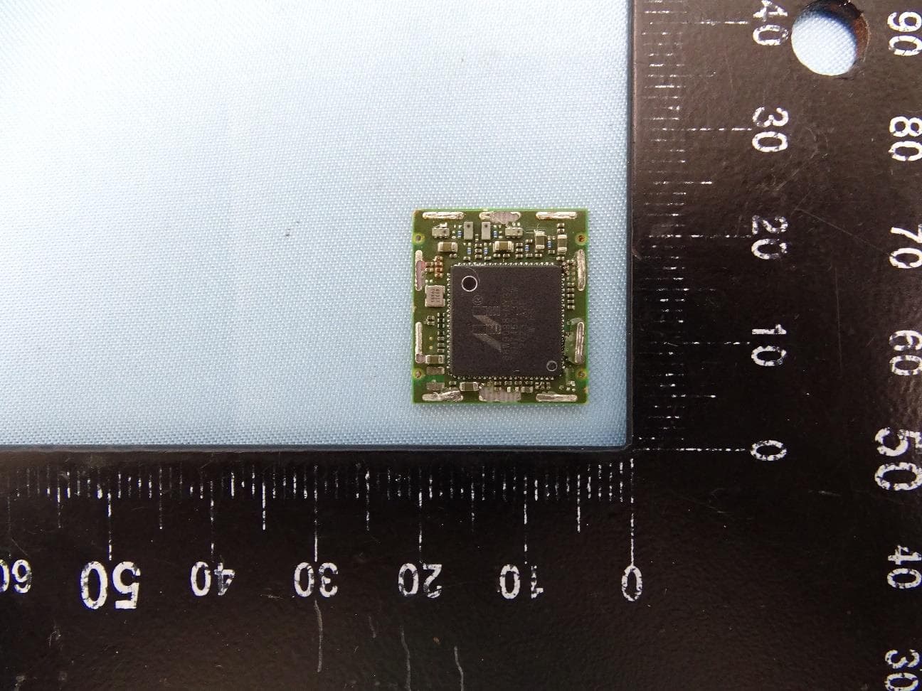
I28-WYSBHVDXP
May 19, 2021WLAN/BTLE module
Equipment Class
DTS - Digital Transmission System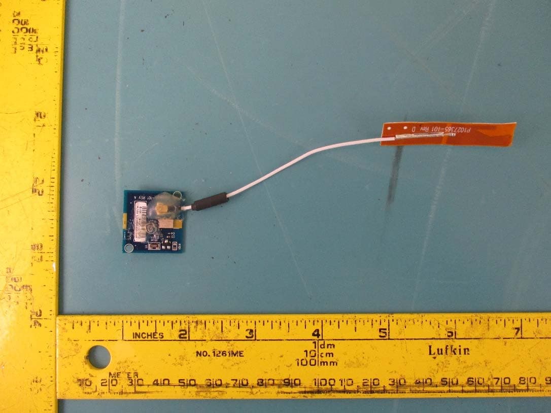
I28-EYSNSNZWWZ1
May 04, 2021BT5 Radio Module
Equipment Class
DTS - Digital Transmission System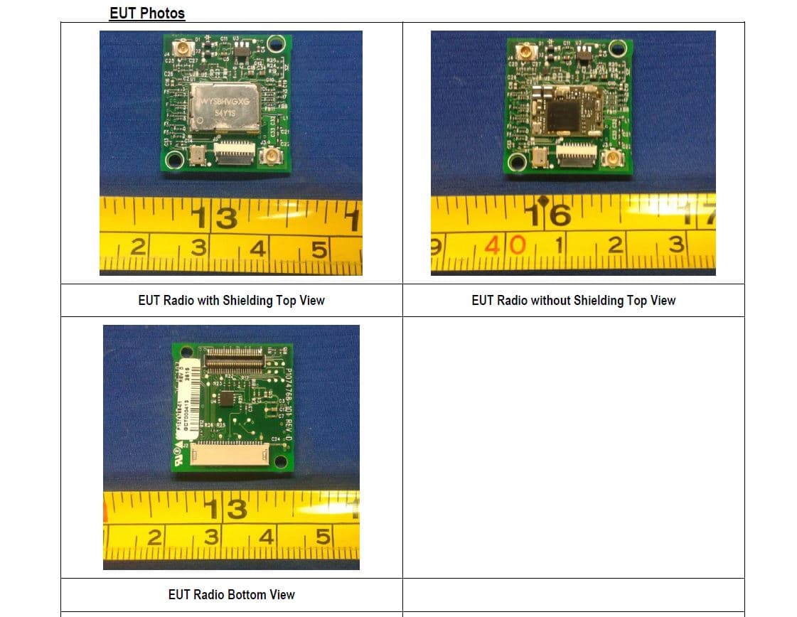
I28MD-FXLAN11AC
Nov 22, 2015Wireless 802.11ac + Bluetooth Module
Equipment Class
DSS - Part 15 Spread Spectrum Transmitter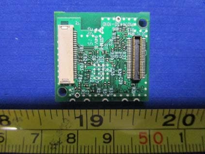
I28MD-ZBRBLE
Nov 19, 2015Bluetooth Low Energy Module
Equipment Class
DTS - Digital Transmission System
I28MD-ZBR7BTLE
Jan 19, 2015Bluetooth 4.0 LE Module
Equipment Class
DSS - Part 15 Spread Spectrum Transmitter