I2ODPA4040EPCS Dual Amplifer Booster/Combiner
Powerwave Technologies, Inc.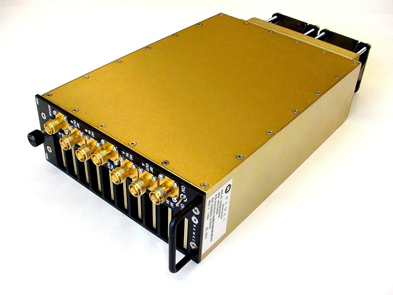
Click to zoom
Application Details
- Equipment Class
- AMP - Amplifier
- Date of Grant
- Jul 15, 2003
- Application Purpose
- Original Equipment
- Date of Application
- Jul 15, 2003
- Equipment Note
- PCS Dual Amplifer Booster/Combiner
- Frequency Range
- 1930.40000000 - 1989.60000000
- Company
- Powerwave Technologies, Inc.
- Country
- United States
Documents & Files
Document Text
Text extracted from the exhibit documents filed with the FCC. Open a document above to read the original.
Users Manual
1590 Buckeye Drive Milpitas, CA 95035 USER MANUAL PCS EDGE and GSM Dual Power Amplifier REMEC Model DPA-4040E DPA-4040E User Manual Rev 1 Page 1 of 1 DPA-4040E User Manual REMEC’s PCS Edge-GSM Dual Power Amplifier Model DPA-4040E product consists of two power amplifiers and a power combiner integrated into one compact housing capable of amplifying and / or combining one or two PCS 1900 Edge or GSM modulated RF carriers. Two supplied user jumper cables allow the user to combine the 2 independent and isolated RF radio carriers into one common output port via the integrated power combiner. This option reduces the available output power for each RF carrier to 46 dBm per carrier, or a composite 2- carrier power of 49 dBm. This mode of operation is noted as Combined Output Mode. The user has the option of removing the jumper cables and connecting directly to the two independent isolated output connectors of the Dual Power Amplifier. In this configuration, the output power for each output port is 49.5 dBm separately. This mode of operation is noted as Isolated Output Mode The DPA-4040E has factory configurable gain only, so input power adjustments must be made by the user in order to adjust the output power. This product has integrated DC power-conditioning circuits, monitoring circuits, control circuits, digital interface circuits and fans. The available monitoring, control circuitry, and digital interface circuits can be factory configured to meet customer needs of capability and cost flexibility. The DPA-4040E is a piece of a larger product solution that allows for up to 6 DPAs to be placed in a common shelf side by side in a 19 inch Rack. The larger product solution consists of an AC to DC power rectifier and a cable kit to interface input signal, output signal, AC and DC power to OEM radio equipment. The larger product solution has an optional Amplifier Monitoring Module (AMM) that can interface to OEM base station alarms or local monitoring by means of a Graphical User Interface (GUI). The entire larger product solution is space efficient, consuming only 6RU of height in a 19-inch rack. The following instructions should be followed when installing the unit for service: 1. Installation Instructions 1.1 Apply a 27VDC input voltage to the DC Input connector of the DPA-4040E 1.2 Ensure that the DC Source is capable of delivering up to 25 Amps at 27VDC. 1.3 Apply either an Edge or GSM modulated signal to each RF input port of the DPA-4040E. 1.4 Measure the RF output port to ensure the proper output power is present. 1590 Buckeye Drive Milpitas, CA 95035 USER MANUAL PCS EDGE and GSM Dual Power Amplifier REMEC Model DPA-4040E DPA-4040E User Manual Rev 1 Page 2 of 2 1.5 Adjust the input power level to ensure the output power level is in compliance with the values indicated in Table 1 or Table 2 depending upon the mode of operation (Combined or Isolated). 1.6 To comply with the FCC limits at the second harmonic, 20 dB minimum rejection must be provided between the DPA and free space. Any or all of the following system elements can be utilized to provide the required rejection: 1.6.1 A transmit filter 1.6.2 A transmit duplexer 1.6.3 An antenna feed with loss 1.6.4 Antenna pattern attenuation Note: The user must adjust the RF input power to the Booster Amplifier such that the RF output power level does not exceed the FCC certified power levels. The FCC certified power level is determined by the RF output spectral emissions to be compliant with the FCC spurious emissions limit of -13 dBm outside of the assigned frequency block. Near the block edges, the Edge and GMSK signal is such that the output power level must be further reduced so that the -13 dBm spurious level is not exceeded. These levels must not be exceeded for FCC compliance. 1590 Buckeye Drive Milpitas, CA 95035 USER MANUAL PCS EDGE and GSM Dual Power Amplifier REMEC Model DPA-4040E DPA-4040E User Manual Rev 1 Page 3 of 3 2. Table 1: Maximum Combined Mode Output Power per Carrier (Edge or GSM) Block Channel Center Frequency (MHz) Maximum RF Output Power per Carrier (dBm) Combined Port Maximum RF Output Power per Carrier (W) Combined Port A 1930.4 44.628.8 A 1930.6 - 1944.4 46 40 A 1944.6 44.628.8 D 1945.4 44.628.8 D 1945.6 - 1949.4 46 40 D 1949.6 44.628.8 B 1950.4 44.628.8 B 1950.6 - 1964.4 46 40 B 1964.6 44.628.8 E 1965.4 44.628.8 E 1965.6 - 1969.4 46 40 E 1969.6 44.628.8 F 1970.4 44.628.8 F 1970.6 - 1974.4 46 40 F 1974.6 44.628.8 C 1975.4 44.628.8 C 1975.6 - 1989.4 46 40 C 1989.6 44.628.8 1590 Buckeye Drive Milpitas, CA 95035 USER MANUAL PCS EDGE and GSM Dual Power Amplifier REMEC Model DPA-4040E DPA-4040E User Manual Rev 1 Page 4 of 4 3. Table 2: Maximum Isolated Mode Output Power Per Carrier (Edge or GSM) Block Channel Center Frequency (MHz) Maximum RF Output Power per Carrier (dBm) Each Isolated Port Maximum RF Output Power per Carrier (W) Each Isolated Port A 1930.4 48.164.5 A 1930.6 - 1944.4 49.5 89.1 A 1944.6 48.164.5 D 1945.4 48.164.5 D 1945.6 - 1949.4 49.5 89.1 D 1949.6 48.164.5 B 1950.4 48.164.5 B 1950.6 - 1964.4 49.5 89.1 B 1964.6 48.164.5 E 1965.4 48.164.5 E 1965.6 - 1969.4 49.5 89.1 E 1969.6 48.164.5 F 1970.4 48.164.5 F 1970.6 - 1974.4 49.5 89.1 F 1974.6 48.164.5 C 1975.4 48.164.5 C 1975.6 - 1989.4 49.5 89.1 C 1989.6 48.164.5 4. Tune-Up Procedure There are no user tunable components in the design so no Tune-up procedure is required. 5. FCC Part 24 compliance Changes or Modifications, not expressly approved by the manufacturer, could void the user's authority to operate the equipment. FCC rules for RF exposure require that the antenna connected to this DPA-4040E equipment is fixed on an outdoor structure with a minimum separation distance of 2 meters between it and any person.
Users Manual
1590 Buckeye Drive Milpitas, CA 95035 USER MANUAL PCS EDGE and GSM Dual Power Amplifier REMEC Model DPA-4040E DPA-4040E User Manual Rev 3 Page 1 of 4 DPA-4040E User Manual REMEC’s PCS Edge-GSM Dual Power Amplifier Model DPA-4040E product consists of two power amplifiers and a power combiner integrated into one compact housing capable of amplifying and / or combining one or two PCS 1900 Edge or GSM modulated RF carriers. Two supplied user jumper cables allow the user to combine the 2 independent and isolated RF radio carriers into one common output port via the integrated power combiner. This option reduces the available output power for each RF carrier to 46 dBm per carrier, or a composite 2- carrier power of 49 dBm. This mode of operation is noted as Combined Output Mode. The user has the option of removing the jumper cables and connecting directly to the two independent isolated output connectors of the Dual Power Amplifier. In this configuration, the output power for each output port is 49.5 dBm separately. This mode of operation is noted as Isolated Output Mode The DPA-4040E has factory configurable gain only, so input power adjustments must be made by the user in order to adjust the output power. This product has integrated DC power-conditioning circuits, monitoring circuits, control circuits, digital interface circuits and fans. The available monitoring, control circuitry, and digital interface circuits can be factory configured to meet customer needs of capability and cost flexibility. The DPA-4040E is a piece of a larger product solution that allows for up to 6 DPAs to be placed in a common shelf side by side in a 19 inch Rack. The larger product solution consists of an AC to DC power rectifier and a cable kit to interface input signal, output signal, AC and DC power to OEM radio equipment. The larger product solution has an optional Amplifier Monitoring Module (AMM) that can interface to OEM base station alarms or local monitoring by means of a Graphical User Interface (GUI). The entire larger product solution is space efficient, consuming only 6RU of height in a 19-inch rack. The following instructions should be followed when installing the unit for service: 1. Installation Instructions 1.1 Apply a 27VDC input voltage to the DC Input connector of the DPA-4040E 1.2 Ensure that the DC Source is capable of delivering up to 25 Amps at 27VDC. 1.3 Apply either an Edge or GSM modulated signal to each RF input port of the DPA-4040E. 1.4 Measure the RF output port to ensure the proper output power is present. 1590 Buckeye Drive Milpitas, CA 95035 USER MANUAL PCS EDGE and GSM Dual Power Amplifier REMEC Model DPA-4040E DPA-4040E User Manual Rev 3 Page 2 of 4 1.5 Adjust the input power level to ensure the output power level is in compliance with the values indicated in Table 1 or Table 2 depending upon the mode of operation (Combined or Isolated). 1.6 To comply with the FCC limits at the second harmonic, 20 dB minimum rejection must be provided between the DPA and free space. Any or all of the following system elements can be utilized to provide the required rejection: 1.6.1 A transmit filter 1.6.2 A transmit duplexer Note: The user must adjust the RF input power to the Booster Amplifier such that the RF output power level does not exceed the FCC certified power levels. The FCC certified power level is determined by the RF output spectral emissions to be compliant with the FCC spurious emissions limit of -13 dBm outside of the assigned frequency block. Near the block edges, the Edge and GMSK signal is such that the output power level must be further reduced so that the -13 dBm spurious level is not exceeded. These levels must not be exceeded for FCC compliance. 1590 Buckeye Drive Milpitas, CA 95035 USER MANUAL PCS EDGE and GSM Dual Power Amplifier REMEC Model DPA-4040E DPA-4040E User Manual Rev 3 Page 3 of 4 2. Table 1: Maximum Combined Mode Output Power per Carrier (Edge or GSM) Block Channel Center Frequency (MHz) Maximum RF Output Power per Carrier (dBm) Combined Port Maximum RF Output Power per Carrier (W) Combined Port A 1930.4 - 1944.6 46 40 D 1945.4 - 1949.6 46 40 B 1950.4 - 1964.6 46 40 E 1965.4 - 1969.6 46 40 F 1970.4 - 1974.6 46 40 C 1975.4 - 1989.6 46 40 3. Table 2: Maximum Isolated Mode Output Power Per Carrier (Edge or GSM) Block Channel Center Frequency (MHz) Maximum RF Output Power per Carrier (dBm) Each Isolated Port Maximum RF Output Power per Carrier (W) Each Isolated Port A 1930.4 - 1944.6 49.5 89.1 D 1945.4 - 1949.6 49.5 89.1 B 1950.4 - 1964.6 49.5 89.1 E 1965.4 - 1969.6 49.5 89.1 F 1970.4 - 1974.6 49.5 89.1 C 1975.4 - 1989.6 49.5 89.1 4. Tune-Up Procedure There are no user tunable components in the design so no Tune-up procedure is required. 5. FCC Part 24 compliance Changes or Modifications, not expressly approved by the manufacturer, could void the user's authority to operate the equipment. 1590 Buckeye Drive Milpitas, CA 95035 USER MANUAL PCS EDGE and GSM Dual Power Amplifier REMEC Model DPA-4040E DPA-4040E User Manual Rev 3 Page 4 of 4 FCC rules for RF exposure require that the antenna connected to this DPA-4040E equipment is fixed on an outdoor structure with a minimum separation distance of 2 meters between it and any person.
Cover Letter(s)
Page 1 of 1 RE: REMEC Inc. FCC ID: I2ODPA4040E 1) It appears that the request for confidentiality is to cover the a) Block Diagram, b) Schematics, c) BOM, and d) Theory of Operation. However these items are not listed consistently throughout the letter. Please correct the letter for consistency so it is clear what items this request is to cover. Response: New revised letter has been uploaded. 2) The FCC has started requiring devices that operate on Part 22H/24E to provide bandedge testing for each block edge. This requires that Part 22H devices be tested at bandedges occurring at bands A, B, A', & B'. Part 24E require bandedge testing at edges of bands A, B, C, D, E, & F. Please provide additional bandedge data for this device as necessary. Please note that it is only necessary to perform this for the worse case modulation. The worse-case modulation accepted by the FCC is considered the one with the widest bandwidth since that will require the greatest 1% measurement RBW to be used. Note that additional data (other than what has already been provided) for other tests such as spurious emissions, power, or other antenna conducted tests are not required. Response: Bandedge plots for all blocks, that are applicable for the amplifier, have been uploaded. The plots are label “DPA-4040E Edge (or GSM) Mod, Block AL (Block A, Low Bandedge), 46 dBm Comb”. The 46 dBm Comb is the mode that the amplifier was tested in. The report data, for the output power, will show that the 46 dBm Comb. is the mode that will produce a 49.0 dBm output power. This is stated so that it is not confused or assumed that the bandedges was tested at 46 dBm. 3) The worse case data for the spurious antenna conducted given in the test report does not match the summary given on page 7 of 15. Please correct. Response: Report has been revised and uploaded with the correction. Hopefully this answers all of your questions. Please contact me via [email protected] if you require more information. Regards, Juan Martinez Sr. EMC Engineer
Cover Letter(s)
American Telecommunications Certification Body Inc. 6731 Whittier Ave, McLean, VA 22101 June 16, 2003 RE: REMEC Inc. FCC ID: I2ODPA4040E After a review of the submitted information, I have a few comments on the above referenced Application. 1) It appears that the request for confidentiality is to cover the a) Block Diagram, b) Schematics, c) BOM, and d) Theory of Operation. However these items are not listed consistently throughout the letter. Please correct the letter for consistency so it is clear what items this request is to cover. 2) The FCC has started requiring devices that operate on Part 22H/24E to provide bandedge testing for each block edge. This requires that Part 22H devices be tested at bandedges occurring at bands A, B, A', & B'. Part 24E require bandedge testing at edges of bands A, B, C, D, E, & F. Please provide additional bandedge data for this device as necessary. Please note that it is only necessary to perform this for the worse case modulation. The worse-case modulation accepted by the FCC is considered the one with the widest bandwidth since that will require the greatest 1% measurement RBW to be used. Note that additional data (other than what has already been provided) for other tests such as spurious emissions, power, or other antenna conducted tests are not required. 3) The worse case data for the spurious antenna conducted given in the test report does not match the summary given on page 7 of 15. Please correct. Timothy R. Johnson Examining Engineer mailto: [email protected] The items indicated above must be submitted before processing can continue on the above referenced application. Failure to provide the requested information may result in application termination. Correspondence should be considered part of the permanent submission and may be viewed from the Internet after a Grant of Equipment Authorization is issued. Please do not respond to this correspondence using the email reply button. In order for your response to be processed expeditiously, you must submit your documents through the AmericanTCB.com website. Also, please note that partial responses increase processing time and should not be submitted. Any questions about the content of this correspondence should be directed to the sender.
Cover Letter(s)
American Telecommunications Certification Body Inc. 6731 Whittier Ave, McLean, VA 22101 July 9, 2003 RE: REMEC Inc. FCC ID: I2ODPA4040E After a review of the submitted information, I have a few comments on the above referenced Application. 1) Your response for item 2 is confusing. It appears that the amplifier was tested with a 46 dBm per carrier combined output (46 or 44.6 dBm per carrier/49.0 combined power). If so, the Isolated output actually is higher power per channel (49.5 dBm or 48.1 dBm as appropriate) and would therefore be considered worse case to test at the bandedges. Note: Users Manual: Isolated Mode = 49.5 dBm per carrier, 48.1 dBm at bandedge channels Combined Mode = 46 or 44.6 dBm per carrier / 49 dBm combined power Please provide further information and/or plots as necessary. Timothy R. Johnson Examining Engineer mailto: [email protected] The items indicated above must be submitted before processing can continue on the above referenced application. Failure to provide the requested information may result in application termination. Correspondence should be considered part of the permanent submission and may be viewed from the Internet after a Grant of Equipment Authorization is issued. Please do not respond to this correspondence using the email reply button. In order for your response to be processed expeditiously, you must submit your documents through the AmericanTCB.com website. Also, please note that partial responses increase processing time and should not be submitted. Any questions about the content of this correspondence should be directed to the sender.
Cover Letter(s)
1590 Buckeye Drive Milpitas, CA. 95035 Page 1 of 1 Federal Communications Commission 7435 Oakland Mills Road Columbia, MD 21046 06/03/2003 Dear Examiner: I am writing to avoid the possibility of an inadvertent disclosure of proprietary information on REMEC’s EDGE Dual Amplifier Booster/ Combiner model number DPA4040E. . The accompanying Form 731 is being filed with the commission on our behalf by Elliott Laboratories, Inc., a consulting and testing laboratory. Included, as exhibits with the enclosed application are block diagrams, schematics, BOMs (Bill of Materials), and theory of operations. It is our intention to provide the commission with a full disclosure of our product so that its merits can be evaluated. Indeed, we are pleased to provide any further information that the commission might wish to see. It is not our intention, however, to make our proprietary process a matter of public record. In view of the fact that the block diagrams, schematics, BOMs, and associated theory of operation disclose the mechanism of our process, we ask that these portions (block diagrams, schematics, BOMs, and theory of operation) of our application be withheld from public inspection as provided under FCC section 0.459. These documents contain details of the proprietary operation of product. These details are not readily discernible - even to technically sophisticated individuals - from our hardware and constitute trade secrets. We request therefore that these documents and this letter be segregated from the body of our evaluation report and withheld from public inspection. Thank you for your attention. Please let the undersigned know if the Commission disagrees with our position or requires further justification. Sincerely, Mandel H. Berenberg, Quality Manager
Cover Letter(s)
• 1590 Buckeye Drive Milpitas, CA 95035 To: FCC Equipment Authorization Branch, FCC reviewer Re: FCC ID: I2ODPA4040E Applicant: REMEC Inc Correspondence Reference Number: 8981 731 Confirmation Number: TC685398 This correspondence is to confirm that the referenced product will not be sold to the general public. The product will be sold only to licensed providers and installed by the provider and/or REMEC personnel. Your Truly Mandel H. Berenberg Sr. Quality Manager [email protected] (408) 501 1164
ID Label/Location Info
LOCATION
Test Setup Photos
Photo# 1 Photo# 2
Contact Information
Applicant
Robert Biedka(Sr. Quality Engineer)
Technical Contact
Elliott Laboratories Inc.Juan Martinez
[email protected]408-245-7800
684 West Maude Ave. · Sunnyvale, California · United States
Non-Technical Contact
Elliott Laboratories Inc.Juan Martinez
[email protected]408-245-7800
Test Firm
Elliott Laboratories LLCDavid Bare
Technical Specifications
| # | Rule Parts | Frequency Range | Power Output | Emission | Tolerance |
|---|---|---|---|---|---|
| 2 | 24 | 1.93 GHz - 1.99 GHz | 89.1 W | G7W | Amp |
Other Applications from Powerwave Technologies, Inc.
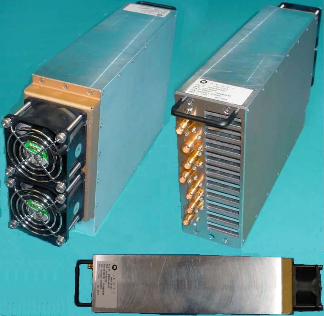
I2ODPA4040G
Mar 09, 2003PCS Dual Amplifier Booster/Combiner
Equipment Class
AMP - Amplifier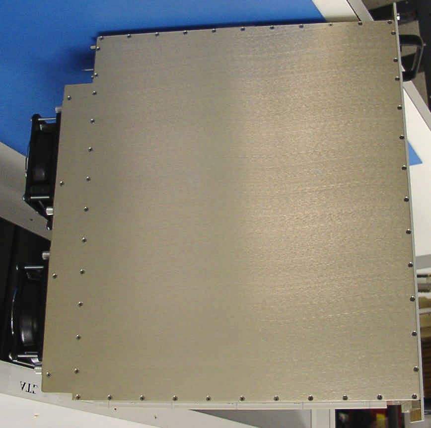
I2OMCPA4080
Dec 05, 2001PCS Multicarrier Ultra-Linear Power Amplifier
Equipment Class
AMP - Amplifier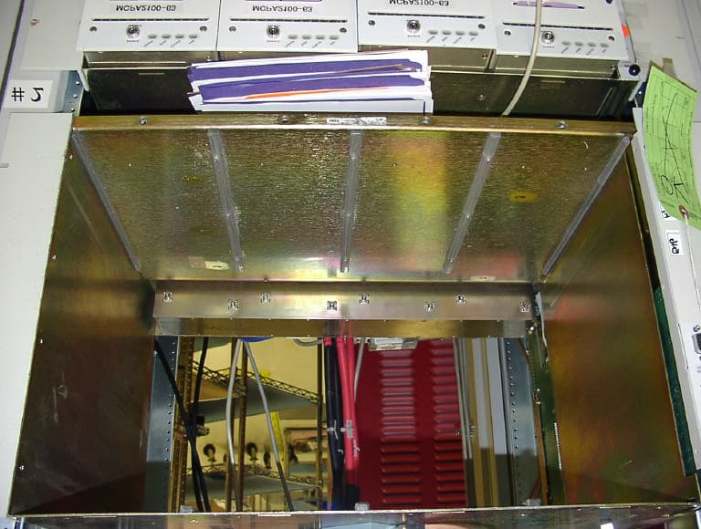
I2OMCPS2135
Aug 06, 2001MultiCarrier Amplifier System
Equipment Class
AMP - Amplifier
I2OMCPS2000
Mar 16, 1999350 Watt Multi-Carrier Power Amplifier
Equipment Class
AMP - AmplifierI2O-ORIOLE1
Feb 01, 1999Single channel PCS Base station unit
Equipment Class
AMP - Amplifier