I2OMCPS2000350 Watt Multi-Carrier Power Amplifier
Powerwave Technologies, Inc.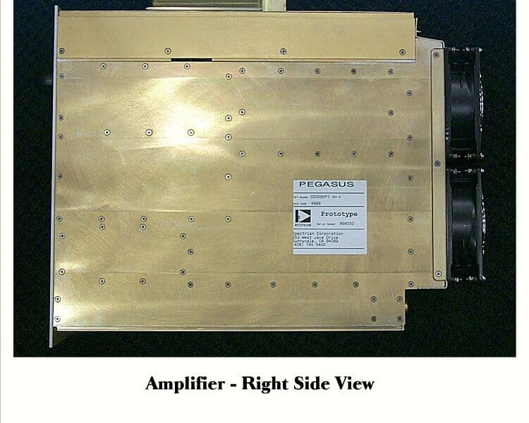
Click to zoom
Application Details
- Equipment Class
- AMP - Amplifier
- Date of Grant
- Mar 16, 1999
- Application Purpose
- Original Equipment
- Date of Application
- Dec 01, 1998
- Equipment Note
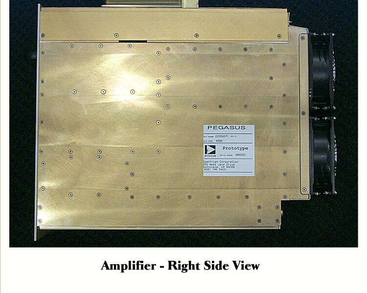
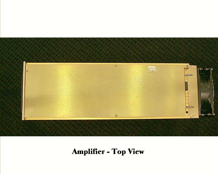
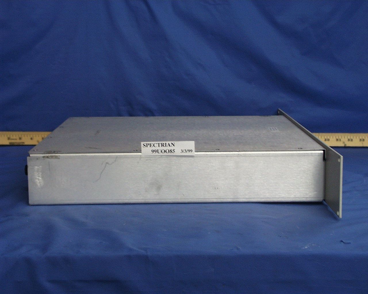
- 350 Watt Multi-Carrier Power Amplifier
- Frequency Range
- 869.00000000 - 894.00000000
- Company
- Powerwave Technologies, Inc.
- Country
- United States
Documents & Files
Document Text
Text extracted from the exhibit documents filed with the FCC. Open a document above to read the original.
Users Manual
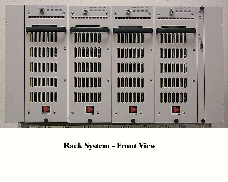
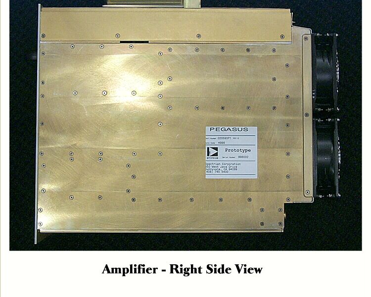
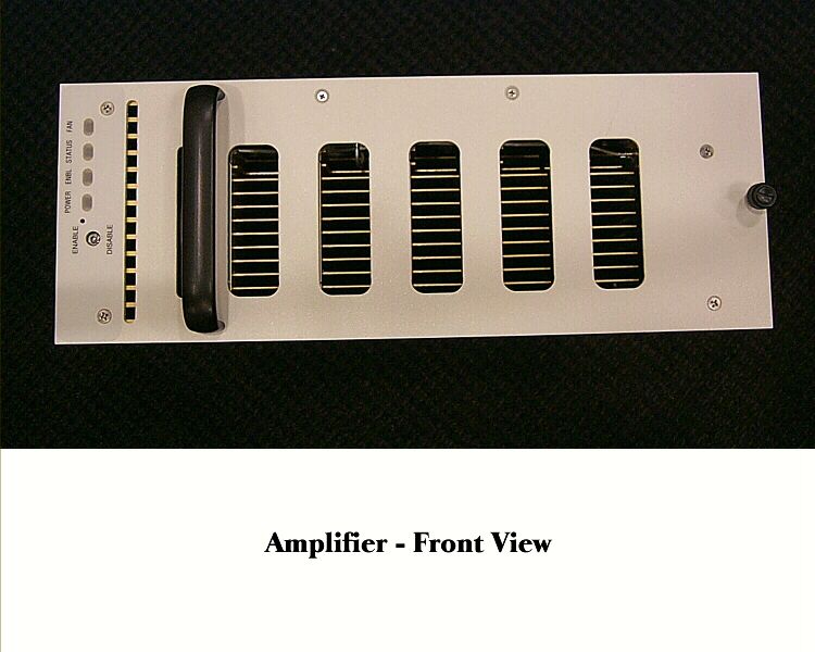
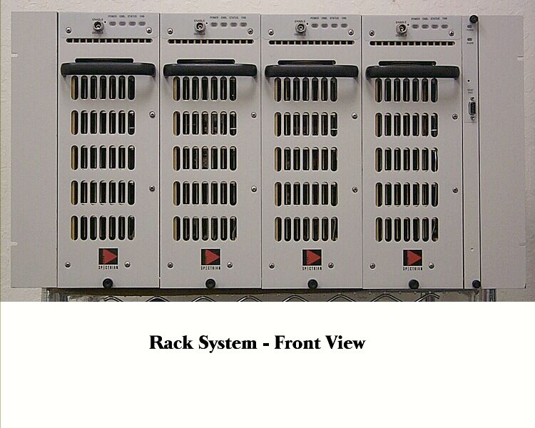
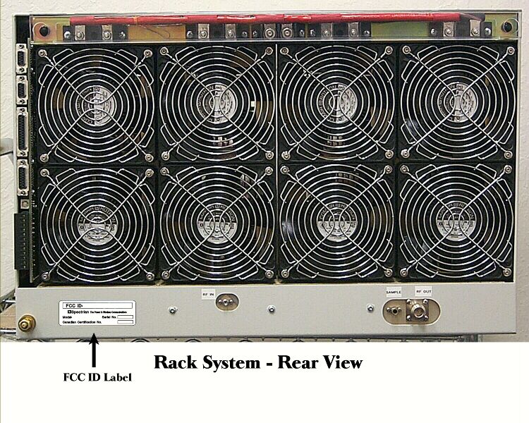
MCPS2000 Operations Manual Spectrian Proprietary This document contains proprietary information of Spectrian, Inc. and may not be used or disclosed except in accordance with applicable agreements. Copyright © Spectrian, Inc. All rights reserved. 1 1 Introduction This chapter introduces the MCPS2000 Series of Multi Carrier Power Amplifier (MCPA) Systems. It describes structure of this manual and introduces the different MCPS2000 Series amplifiers. 1.1 About this Manual This Manual describes how to install, operate, and maintain the MCPS2000 series of amplifiers. It is arranged in chapters. Chapter 1, Introduction, introduces the systems in the MCPS2000 family and their main features and describes how the system documentation is organized. Chapter 2, Installation and Operation, describes how to install the MCPS2000 amplifier and place the amplifer in service. Chapter 3, Troubleshooting, describes how to diagnose faults using the indicator LEDs and status/alarm messages. Chapter 4, Field Service Procedures, describes how to perform routine maintenance and install new field-replaceable modules in the MCPS2000 amplifier. The Specifications Appendix details the electrical, mechanical, and environmental specifications met by this MCPS2000 amplifier, including the Connector Pinouts and Interface Protocols used in the front panel diagnostic port and the optional base station alarm and control interfaces. 1.2 Introduction to the MCPS2000 Family The MCPS2000 is a modular, ultra-linear cellular-frequency amplifier system providing up to 350 Watts (total) of output power. Designed for maximum flexibility and reliability, the MCPS2000 can increase the range or capacity of both new and existing base stations. Modulations The MCPS2000 can amplify any number of signal carriers using AMPS, CDPD, IS- 136 TDMA, or IS-95 CDMA modulation up to the maximum rated system output power. Introduction to the MCPS2000 Family MCPS2000 Operations Manual Spectrian Proprietary -- See notice on first page 2 Modularity The MCPS2000 family is designed for operation with 1 to 4 amplifier modules, each providing 100 Watts of RF output power (up to 90 Watts effective output after combining losses). Installation The MCPS2000 housing is an 8RU shelf. Mounting kits are available for installation in 23-inch, 600mm, 24-inch, or 25-inch equipment racks. RF Interfaces It has a single RF input for the combined input signals, and a single RF output to the transmit filter. Alarms and Control The MCPS2000 provides status information through front-panel LED indicators and an RS-232 status port. Status information can be viewed through a front-panel RS- 232 port using either a VT-100 terminal emulation program or Spectrian’s Graphical User Interface program. The MCPS2000 can also be optionally equipped with additional alarm and control interfaces, including dry-contact or TTL alarm connections and RS-485 or RS-422 interfaces to network operations and administration systems. Reliability The MCPS2000 is designed to enable system maintenance without removing the amplifier from service. The amplifier and system control modules can be hot- swapped during operation without affecting calls in process. The amplifier modules are designed so the cooling fans can be refit in the field by qualified service technicians, greatly reducing service shipping costs and turn-around time. 1.2.1 MCPS2000 Systems Modules A fully-equipped MCPS2000 consists of a rack-mounted shelf containing up to four RF modules, an Alarm Management Module, and an internal divider/ combiner. RF modules The RF modules are ultra-linear amplifiers optimized for high power amplification of cellular signals. After combining losses, each RF module provides up to 90 Watts of RF output power. Amplifier Management Module The Amplifier Management Module contains the system control and alarm management logic and the interface to external operations and control systems. Divider/Combiner The divider/combiner allows the four RF modules to function as a single system. The divider/combiner has an active architecture, which automatically reconfigures to minimize combining losses if a RF module should fail. Introduction MCPS2000 System Operation3 Spectrian Proprietary -- See notice on first page Major Equipment Specifications for the MCPS2000 Electrical SpecificationsSpecification @ 25ºC Frequency Range869 - 894 MHz Average Power¹ into 50 Ohms100W (50 dBm) to 350W (55.4 dBm) Intermodulation Distortion (IMD)-65 dBc with AMPS and/or TDMA IS-136, or IS-97 CDMA dual mode input sources under nominal conditions CDMA Adjacent Channel Power 3 < -45 dBc, 750 KHz offset, 30 KHz res bandwidth @ 881 MHz, 100W Output< -60 dBc, 1.98 MHz offset, 30 KHz res bandwidth Receive Band Noise-30 dBm/30 kHz bandwidth Carrier Spacing (AMPS/TDMA)60 KHz min., 25 MHz max. Power Output Stability for Single Frequency± 0.5 dB under nominal conditions Operating Bandwidthup to 25 MHz GainFactory set, 30 to 60 dB, 85 dB with optional preamp Gain Flatness vs. Frequency± 0.5 dB (over all temps) Gain Variation over Temp @ Any Inband Frequency ± 1 dB Forward Power Sample Port Gain-50 dB typ. Input/Output Port Return Loss-15 dB min. Second/Third and Greater Harmonic Output-13 dBm/-20 dBm max. DC Input Voltage Range26 to 28 VDC 2 DC Input Current @ 27VDC (max)100W single RF module – 42A 175W two RF modules – 87A 260W three RF modules –130A 350W four RF modules – 170A 1 Power levels at the output of the system combiner will vary depending on the configuration. 2 Reduced power performance over 21-26V. Full spec performance (22-30V) available with optional DC/DC converter. 3 Measured at the RF module output connector and in accordance with IS-97. Mechanical Specifications Operating/Storage Temperatures0ºC to 50ºC/-40ºC to 85ºC Size, 4 module system, mounting ears excluded(D x W x H) 17.72 x 21.56 x 13.97 in. max (450 x 547,62 x 354,84 mm max.) Weight, 4 module system Installed: approx. 230 lbs (105 kg) Shipping: approx. 270 lbs max. (125 k…
Text truncated - open the document above for the full version.
Attestation Statements
SPECTRIAN 350 Java Drive Sunnyvale, CA 94089 Phone 408-745-5474 Fax 404-541-0263 December 20, 1998 FCC Confirmation Number: EA92496 FCC ID: I2OMCPS2000 (formally requested as I2OMCPS23504800) We, the undersigned, hereby certify that the above-referenced cellular transmit and receive equipment is in full compliance with all parts of Section 2 of IS-3-D, the EIA Interim Standard on cellular mobile station – land station compatibility, issued March 1987 and with OST Bulletin No. 53, “Cellular System Mobile Station – Land Station Compatibility Specification”. John Pelose General Manager, Multi-Carrier
Cover Letter(s)
SPECTRIAN 350 Java Drive Sunnyvale, CA 94089 Phone 408-745-5474 Fax 404-541-0263 December 20, 1998 Federal Communications Commission c/o Mellon Bank Three Mellon Bank Center 525 William Penn Way 27 th Floor, Room 153-2713 Pittsburg, PA 15259-001 Attn:Wholesale Lockbox Shift Supervisor Subject:Application for Equipment Authorization FCC ID: I2OMCPS2000 (formally requested as I2OMCPS23504800) Reference:Confirmation Number – EA92496 Please accept the enclosed submittal and our completed FCC Form 731 Application for Equipment Authorization and supporting data/test results for your approval and type acceptance. We have filed in accordance with the Code of Federal Regulations Title 47, Paragraph 2.909 along with a Request for Confidentiality. The submittal is for a Multi-carrier Amplifier System which has highly linear performance for many number of carriers in the US Cellular bands (869-894 MHz). The Multi-carrier Power Amplifier System is used in conjunction with host modulation equipment vendors who provide low level signals in formats such as TDMA, CDMA, AMPS, NAMPS, and CDPD base stations in the Public Cellular Telecommunications Service. The emission designators for this product are: 30K0F1D, 30K0F2D, 30K0F3D, 30K0F3E, 30K0F8W, 30K0DXW, and 30K0F9W. Spectrian has been asked by its customers to provide an RF power amplifier product family which will range in output power levels and which will provide a high C/I ratio for signals that are amplified significantly to enhance carrier transmission service in base station applications. Page 2 December 20, 1998 The accumulation of technical test data to support our application was prepared under the supervision of Chris Gonzales, Reliability Engineer. Enclosed are photographs of the new product, circuit diagrams, a photograph showing the lable location, as well as a copy of the FCC indentifier label which will be affixed to each system produced. A check for $610.00 is included to cover both fees as per the FCC Fee Filing Guide. I hereby certify that this application was prepared at my direction and that to the best of my knowledge and belief, the facts set forth in this letter and the accompanying enclosures are true and correct. In the event that questions arise, please feel free to contact the undersigned at (408) 745-5449. Sincerely, Richard Hauck Director, MCPA Sales
Cover Letter(s)
SPECTRIAN 350 Java Drive Sunnyvale, CA 94089 Phone 408-745-5474 Fax 404-541-0263 December 20, 1998 Federal Communications Commission Equipment Approval Services P.O. Box 358315 Pittsburgh, PA 15251-5315 Reference:FCC Confirmation Number: EA92496 FCC ID: I2OMCPS200 (formally requested as I2OMCPS23504800) To Whom It May Concern: In applying for type acceptance for the MCPS2000 Multi-channel power amplifier system, Spectrian requests that certain items be witheld from public inspection upon such type acceptance authorization. This request is made in accordance with FCC section 0.459 (a) and (b). If this request for confidentiality is denied, Spectrian requests that material is returned without consideration pursuant to FCC section 0.459 (e). The listed materials, submitted for review of the request for type acceptance, include trade secrets, which, if made available for public inspection, would seriously damage Spectrian’s competitive advantage. Spectrian’s competition could gain advantage by studying these documents and deduce the unique aspects of our system/amplifier architecture. These trade secrets allow Spectrian to produce an amplifier with lower labor cost, more production performance margin, and better performance over temperature, time, frequency, power level and a number of carriers. In particular, those documents are: Description 1) Schematic Diagram 2) Block Diagram 3) Interconnect Diagrams 4) Function of Active Devices portion of Technical Description 5) Internal Photographs 6) Installation Guidelines Spectrian owned patents and/or patent filings covers several technologies designed into this amplifier. The following is a summary of some of those technologies: Page 2 December 20, 1998 Approved Patents Planer Microstrip Baluns are used in the RF amplifier stages. This technology is covered by Patent # 5,304,959 issued 4/19/94. The RF Power Transistor Package used in the RF devices throughout the amplifier is covered by Patent # 5,338,974 issued 8/16/94. The Method of Thermal Balancing RF Power Transistor Array is covered by Patent # 5,023,189 issued 6/11/94. Patents Pending A patent application has been filed for the Power Stack Basic Power Module (BPM) Architecture used in the main amplification path to maximize power and reliability. Sincerely, John Pelose General Manager, Multi-Carrier
Cover Letter(s)
SPECTRIAN1 of 2 350 Java Drive Sunnyvale, CA 94089 Phone 408-745-5474 Fax 404-541-0263 December 20, 1998 Federal Communications Commission Equipment Approval Services P.O. Box 358315 Pittsburgh, PA 15251-5315 Reference:Correspondence Reference Number:6252 FCC Confirmation Number: EA92496 FCC ID: I2OMCPS2000 Attention:Mr. Frank Coperich Dear Frank : In reply to your e-mail dated Feb. 24,1999. We have revised our request for confidentiality. Please refer to the following statement: In applying for Grant of Certification for the MCPS2000 Multi-channel power amplifier system, Spectrian requests that certain items be witheld from public inspection upon such equipment authorization. This request is made in accordance with FCC section 0.459 (a) and (b). The listed materials, submitted for review of the request for Grant of Certification, include trade secrets, which, if made available for public inspection, would seriously damage Spectrian’s competitive advantage. Spectrian’s competition could gain advantage by studying these documents and deduce the unique aspects of our system/amplifier architecture. These trade secrets allow Spectrian to produce an amplifier with lower labor cost, more production performance margin, and better performance over temperature, time, frequency, power level and a number of carriers. In particular, those documents are: Description 1) “ RF Interconnect “, Document no:WD-020593P1, Total 4 pages 2) “ DC Interconnect “, Document no:WD-020593P1, Total 1 page. 3) “ MCPS2000 MCPA Module Block Diagram”. This Block Diagram is submitted to FCC under the file name : MCP2000 Tech Desc V1, Page 6 under section title 2.983(d)(7) Complete Circuit Diagram. 4) Internal Photographs: Submitted total of 19 internal photos via FCC web site. Request special consideration from the Commission: Spectrian has not completed filing patents for all of the unique design aspects of this product. In some countries, any publicly available disbursement of information constitutes "disclosure" and therefore voids any patent application. The U.S. allows a one year grace period. I believe that Japan is one such country that does not allow this grace period, and we have active competitors in this country. As the result, we are requesting the Commission to withhold internal photos from public disclosure until the patents received from U.S. government. 5)Pre Amp Block Diagram Spectrian owned patents and/or patent filings covers several technologies designed into this amplifier. The following is a summary of some of those technologies: Approved Patents Planer Microstrip Baluns are used in the RF amplifier stages. This technology is covered by Patent # 5,304,959 issued 4/19/94. The RF Power Transistor Package used in the RF devices throughout the amplifier is covered by Patent # 5,338,974 issued 8/16/94. The Method of Thermal Balancing RF Power Transistor Array is covered by Patent # 5,023,189 issued 6/11/94. Patents Pending A patent application has been filed for the Power Stack Basic Power Module (BPM) Architecture used in the main amplification path to maximize power and reliability. Sincerely, John Pelose General Manager, Multi-Carrier
Operational Description
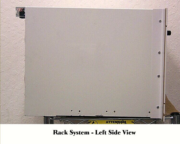
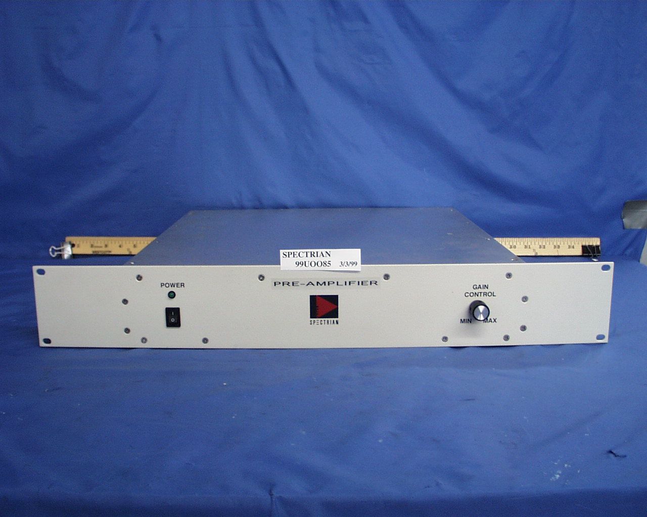
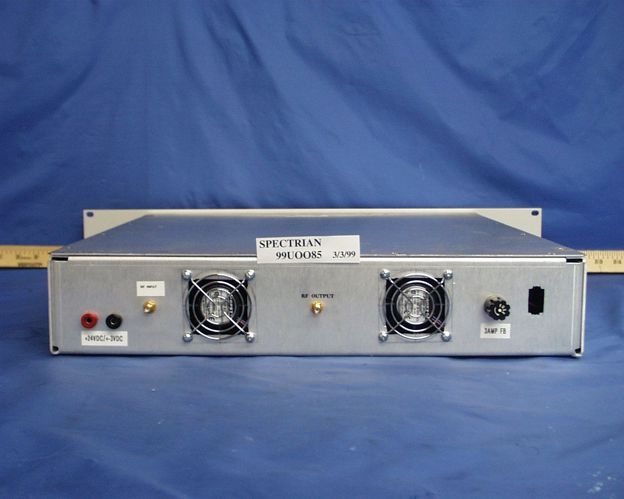
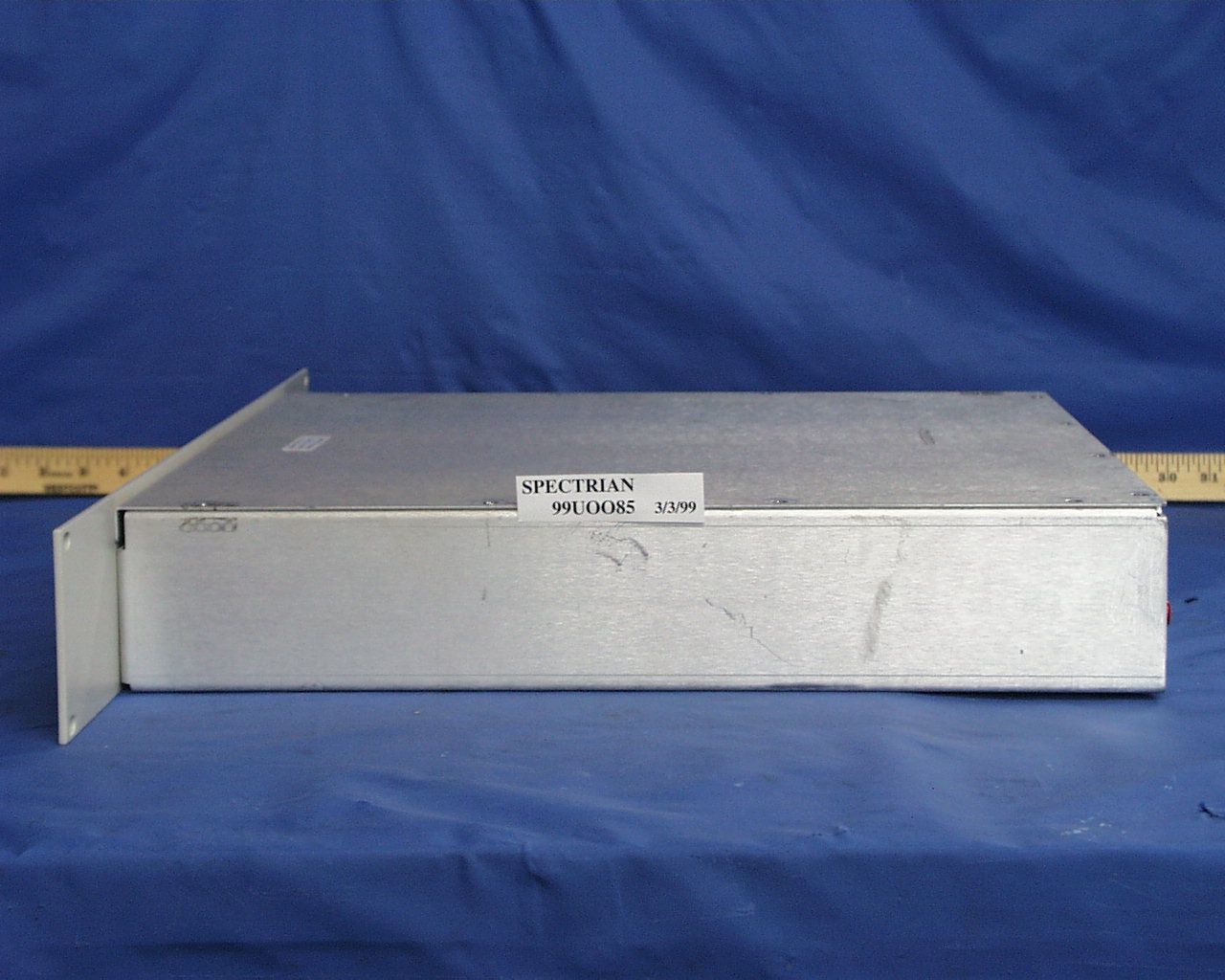
Specifications are subject to change without notice.Spectrian Corporation, 1999 Spectrian Multi-Carrier Pre-Amplifier MCPS-PREAMP-800 Product Specifications Electrical Specifications Frequency Range869-894 MHz RF Gain0 to 20 dB (Adjustable) RF Gain Flatness ± .03 dB Output Power10 mW Input / Output Return Loss15 dB Intermodulation Distortion (IMD)-70 dBc @ 10 mW Carrier Spacing (Amps/TDMA)60 kHz min., 25 MHz max. Output Protection15 dB Isolated DC Voltage Range24 to 28V DC Current @ 27 V DC 1 Amp Noise FigureTBD Supplemental Characteristics Operating Temperature0° - 60°C Storage Temperature-40° - +85°C Operating Humidity5 to 85% (Non-condensing) Storage Humidity5 to 85% (Non-condensing) Connector1. RF Input(s): SMA (F) 2. RF Output: SMA (F) 3. DC Inputs/Ground: 9 Pin D-Sub Size (L x W x H)17 x 19 x 3.5 inches (431.8 x 482.6 x 88.9mm) Weight18 lbs (8.0 kg)
Test Report
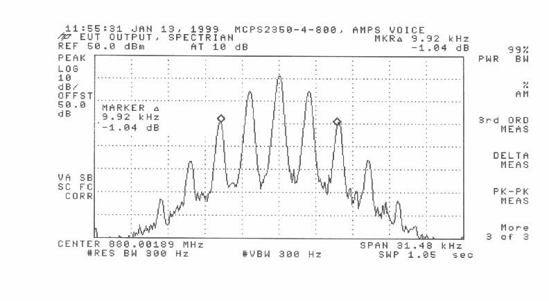
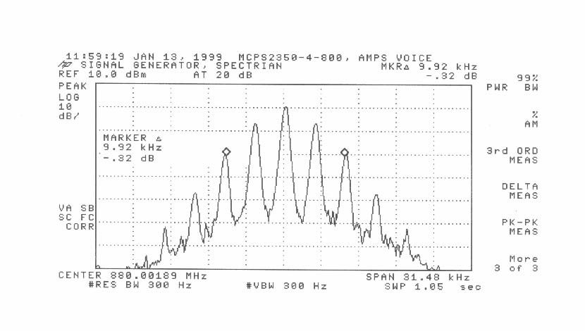
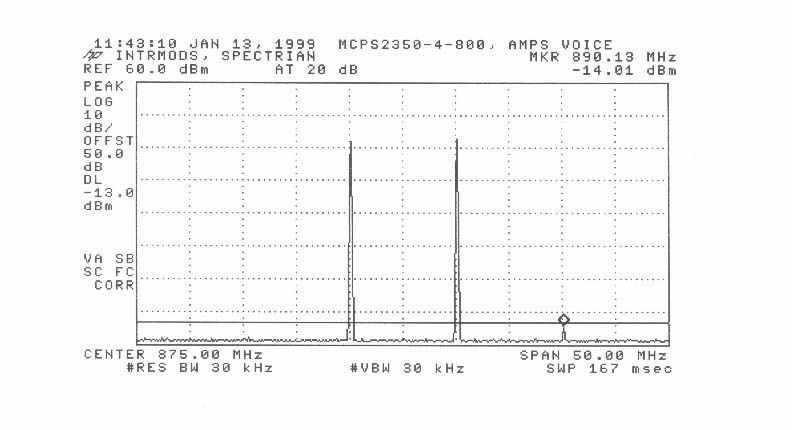
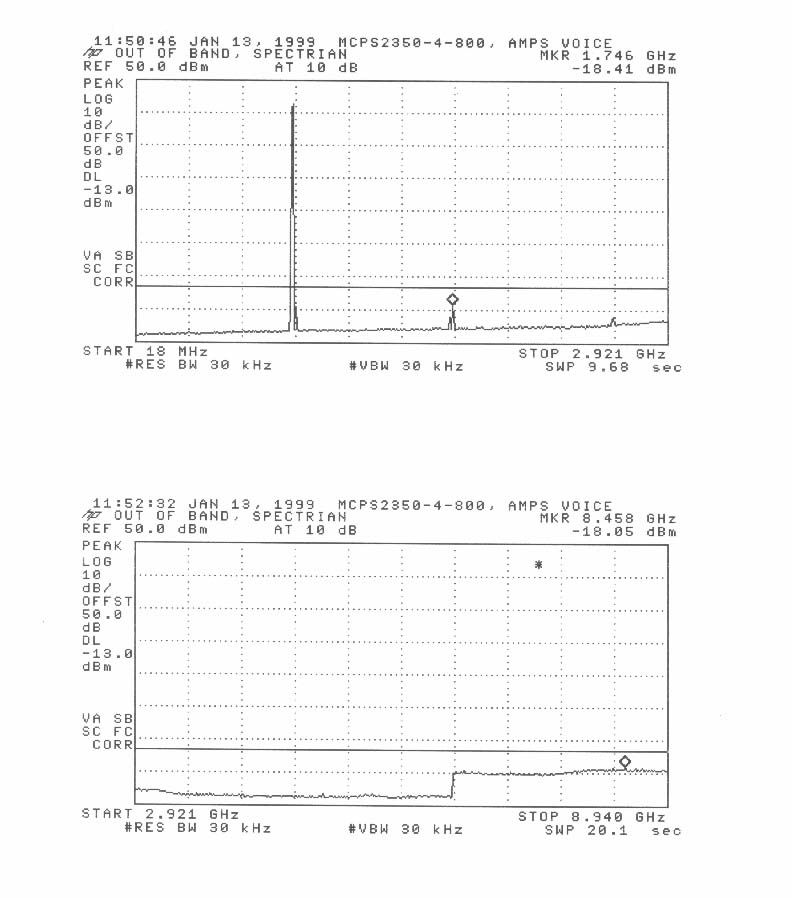
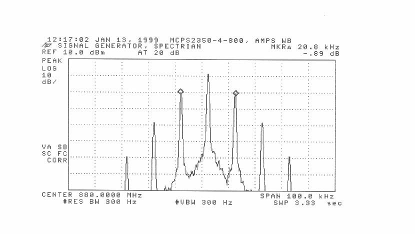
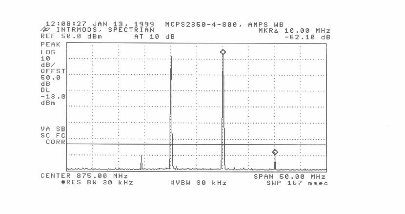
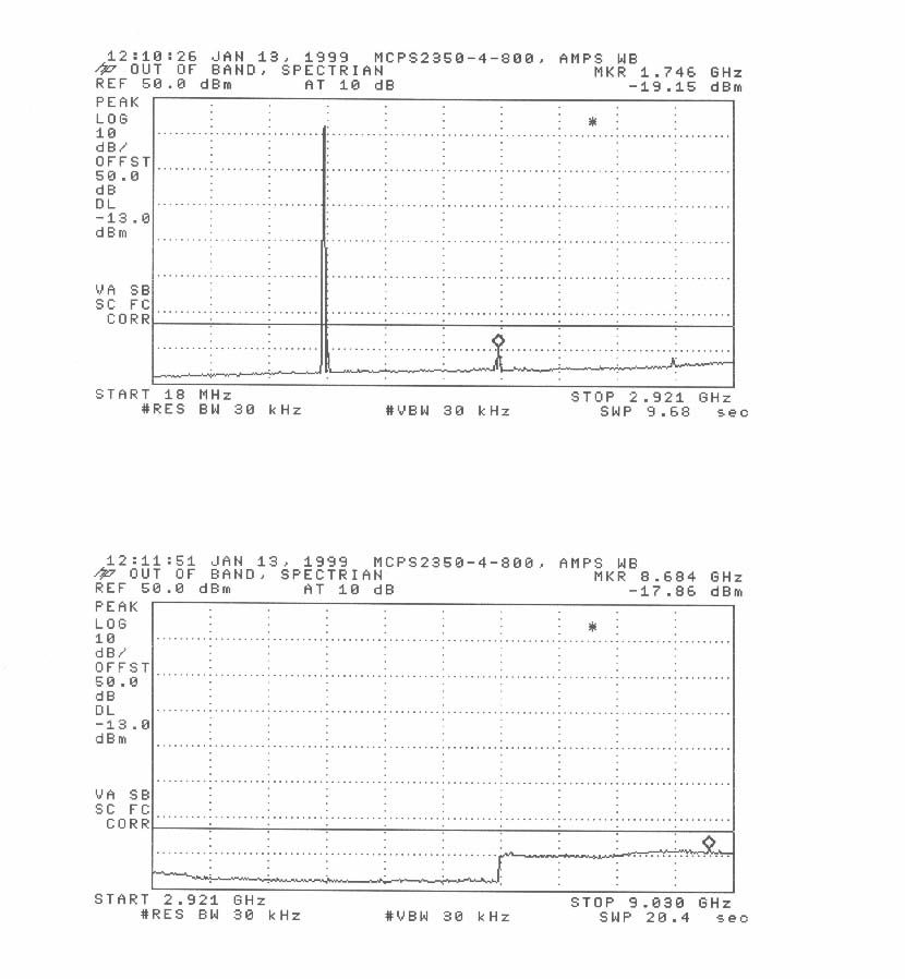
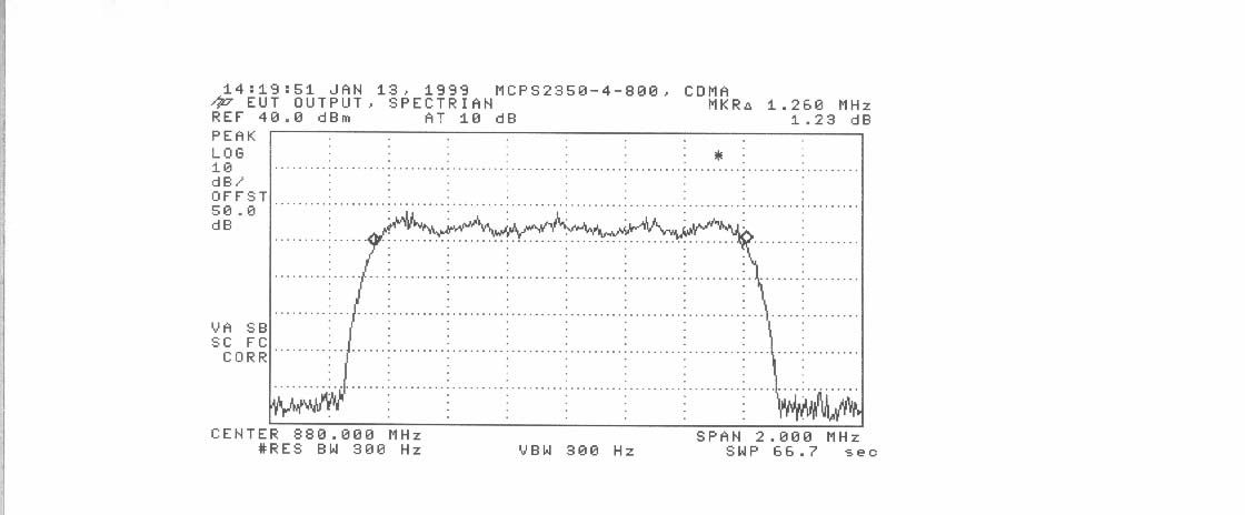
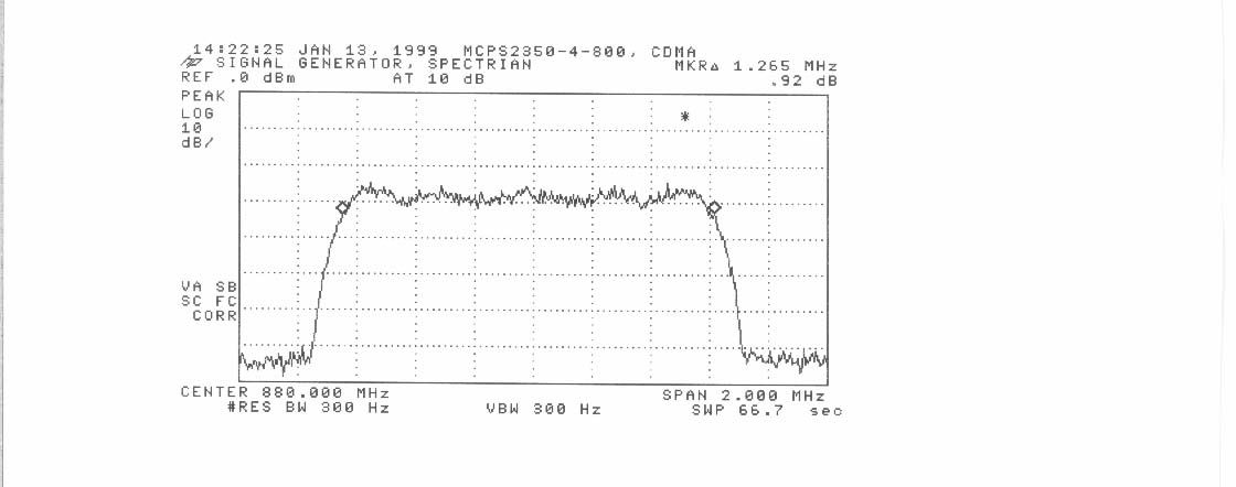
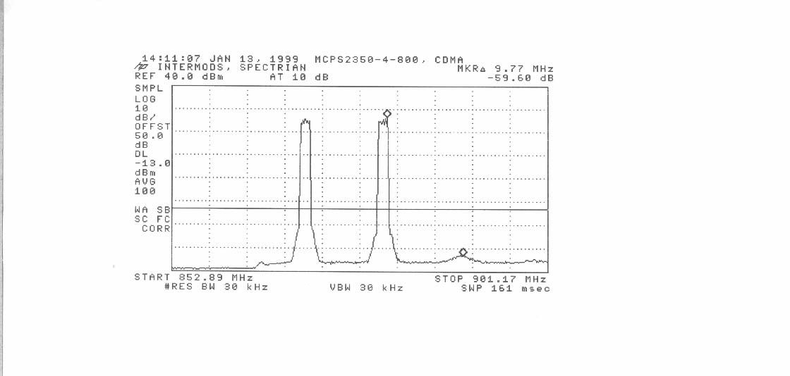
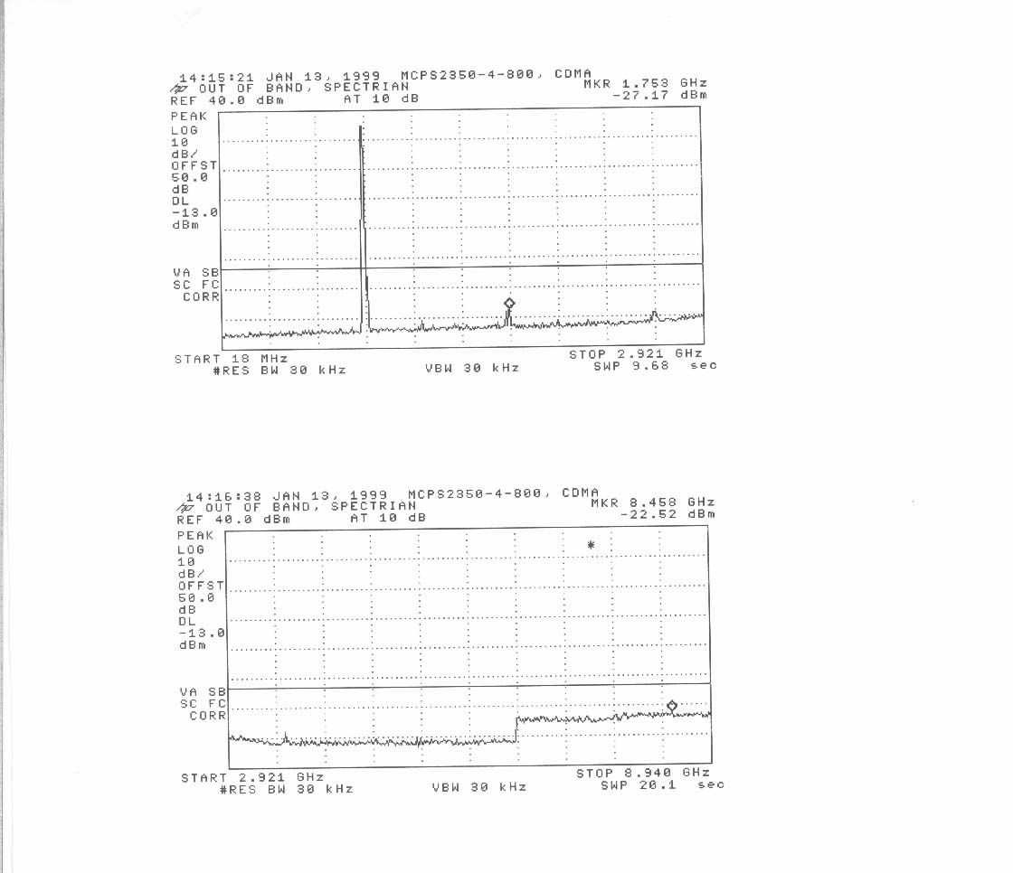
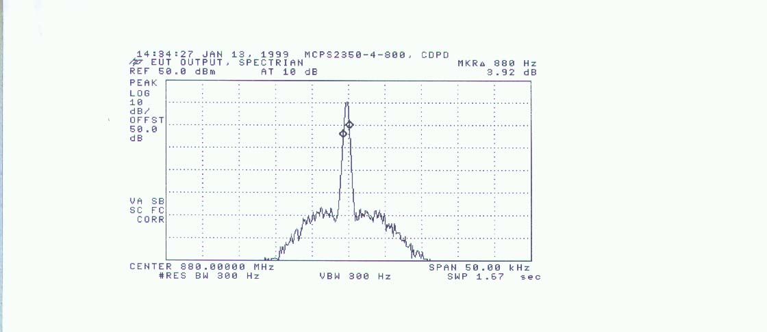
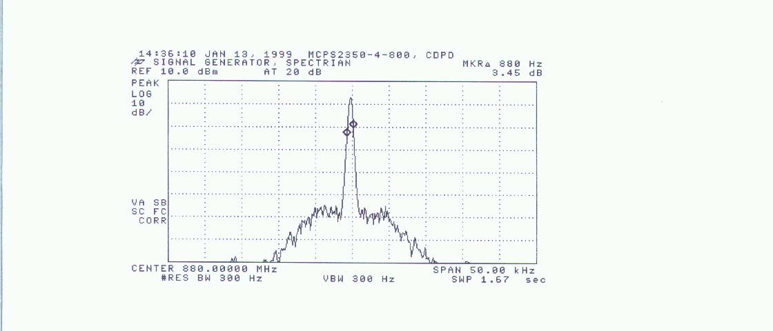
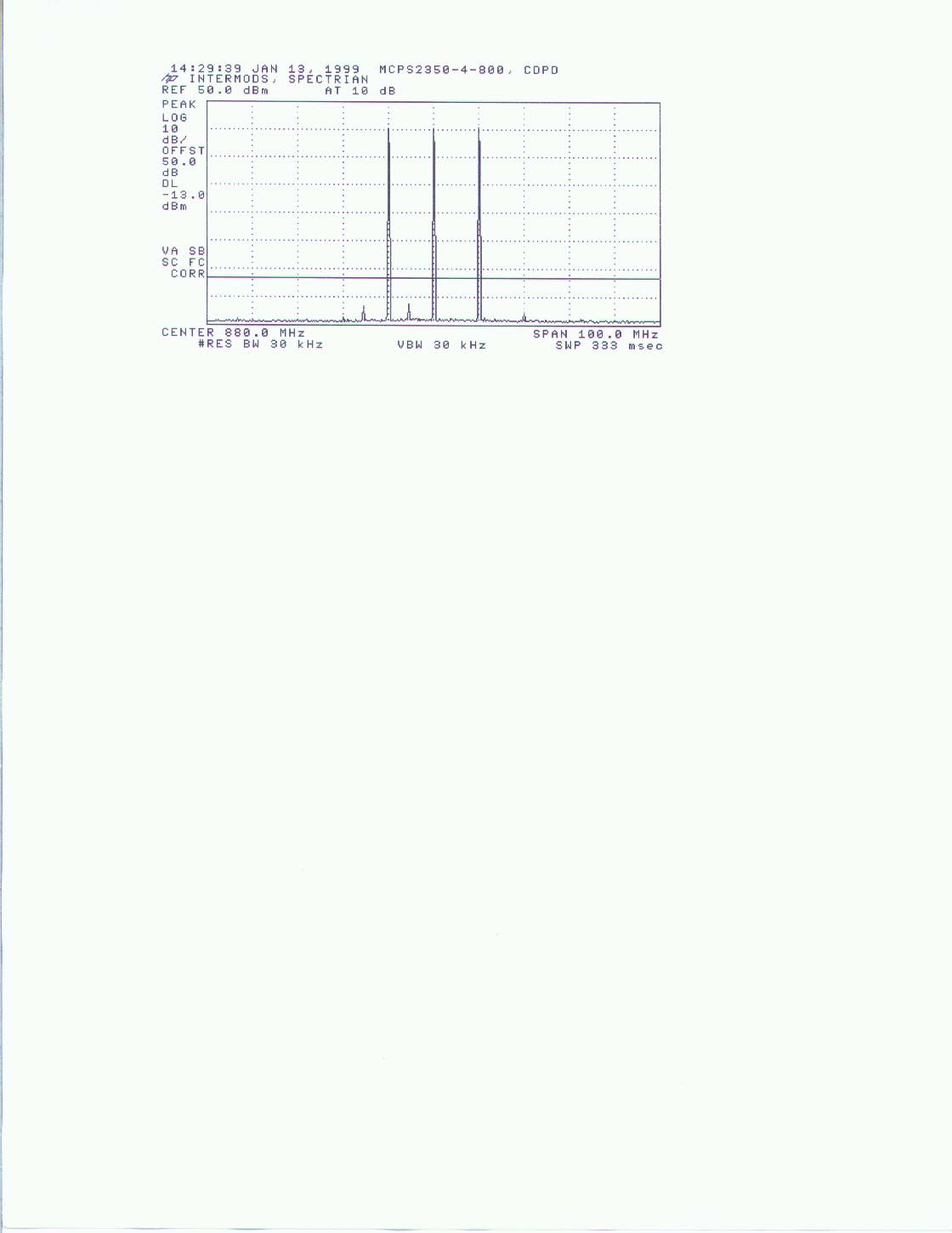
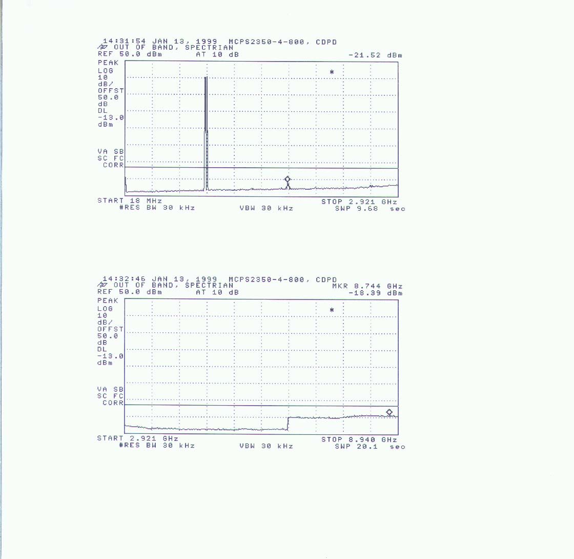
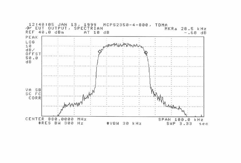
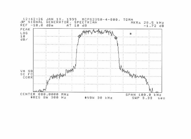
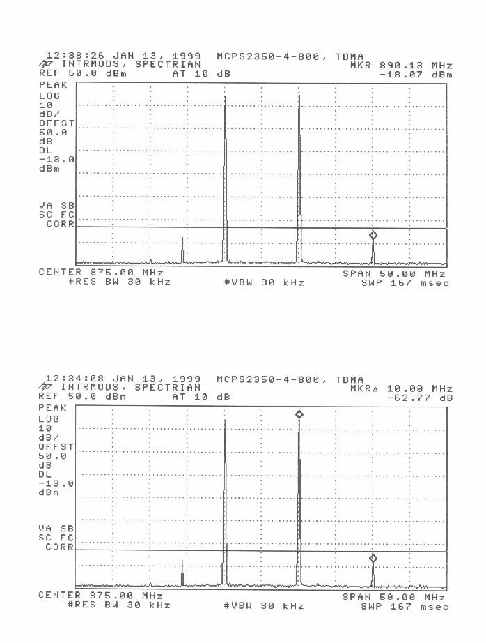
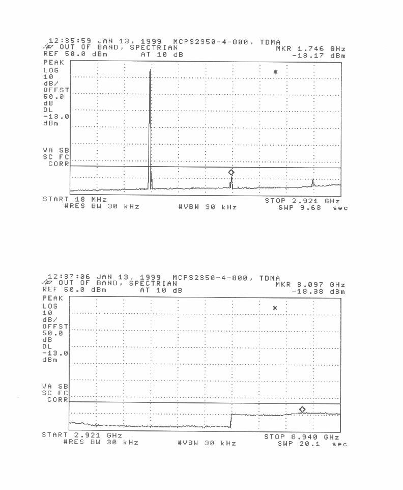
Intertek Testing Services NA Inc. 1365 Adams Court, Menlo Park, CA 94025 Tel 650.463.2900 Fax 650.463.2910 www.worldlab.com i A TEST REPORT FCC Part 22 Type Acceptance Spectrian Power Amplifier Model: MCPS2350-4-800 FCC ID: I2OMCPS2000 Report # J98033279 Date of Report: December 1, 1998 Total No. of Pages Contained in this Report: 33 This report shall not be reproduced except in full, without written approval of Intertek Testing Services. This report must not be used to claim product endorsement by NVLAP or any agency of the U.S. Government. The results contained in this report were derived from measurements performed on the identified test samples. Any implied performance of other samples on this report is dependent on the representative of the samples tested. FCC Part 22 A Spectrian, Power Amplifier Date of Test: November 24, 1998 1 FCC ID:I2OMCPS2000Report # J98033279 Table of Contents 1.0Introduction.........................................................2 1.1Test Summary..................................................2 1.2Product Description..............................................3 2.0RF Power Output.....................................................4 2.1Test Procedure..................................................4 2.2Test Equipment.................................................4 2.3Test Results....................................................4 3.0Effective Radiated Power..............................................8 3.1Test Procedure..................................................8 3.2Test Results....................................................8 4.0Occupied Bandwidth, Emission Limitations...............................9 4.1Test Procedure..................................................9 4.2Test Equipment.................................................9 4.3Test Results....................................................9 5.0Out of Band Emissions at Antenna Terminals.............................13 5.1Test Procedure.................................................13 5.2Test Equipment................................................13 5.3Test Results...................................................13 6.0Field Strength of Spurious Radiation....................................27 6.1Test Procedure.................................................27 6.2Test Equipment................................................27 6.3Test Configuration Setup - Radiated Emissions.........................28 6.4Test Results...................................................29 7.0Line Conducted Emissions............................................31 7.1Test Procedure.................................................31 7.2Test Configuration Setup - Line Conducted Emissions...................31 7.3Test Results...................................................31 8.0Frequency Stability vs Temperature.....................................32 8.1Test Procedure.................................................32 8.2Test Equipment................................................32 8.3Test Results...................................................32 9.0Frequency Stability vs Voltage.........................................33 9.1Test Procedure.................................................33 9.2Test Equipment................................................33 9.3Test Results...................................................33 A Spectrian, Power Amplifier Date of Test: November 24, 1998 FCC ID:I2OMCPS2000Report # J980332792 1.0Introduction 1.1Test Summary FCC RULEDESCRIPTION OF TESTRESULTPAGE 2.985RF Power OutputPass4 22.913Effective Radiated PowerN/A8 2.989(c),Emission Limitation, OccupiedPass9 22.917(b)(d)Bandwidth. 22.917(e)Spurious emissions at antenna terminalsPass13 2.993, 15.109Field Strength of Spurious RadiationPass27 15.107Line Conducted EmissionsN/A31 2.995(a)Frequency Stability vs. TemperatureN/A32 2.995(d)(2)Frequency Stability vs. VoltageN/A33 November 30, 1998 Barry SmithDate Test Engineer A Spectrian, Power Amplifier Date of Test: November 24, 1998 FCC ID:I2OMCPS2000Report # J980332793 1.2Product Description The Spectrian Model MCPS2350-4-800 is a power amplifier operating in the frequency range 869 MHz - 894 MHz For more details, refer to the users manual. A Spectrian, Power Amplifier Date of Test: November 24, 1998 FCC ID:I2OMCPS2000Report # J980332794 2.0RF Power Output, FCC §2.985(a) 2.1Test Procedure The amplifier’s output was connected to a power meter and spectrum analyzer through a calibrated coaxial attenuator and directional coupler. The FM test signal was applied to the amplifier’s input from a signal generator, and the input level was adjusted to obtain 55.4 dBm average output power. 2.2Test Equipment Hewlett Packard 8482A Power Sensor, 438A Power Meter Hewlett Packard 8594E Spectrum Analyzer, 9 kHz - 2.9 GHz 2.3Test Results The average output power is 55.4 dBm (or 350W) measured with a power meter. See also plots attached. A Spectrian, Power Amplifier Date of Test: November 24, 1998 FCC ID:I2OMCPS2000Report # J980332795 A Spectrian, Power Amplifier Date of Test: November 24, 1998 FCC ID:I2OMCPS2000Report # J980332796 A Spectrian, Power Amplifier Date of Test: November 24, 1998 FCC ID:I2OMCPS2000Report # J980332797 A Spectrian, Power Amplifier Date of Test: November 24, 1998 FCC ID:I2OMCPS2000Report # J980332798 3.0Effective Radiated Power, FCC §22.913 Requirement: The Effective Radiated Power (ERP) must not exceed 500 Watts. 3.1Test Procedure Assuming that the EUT has an ideal matching to an antenna the ERP can be calculated as follows: ERP = P + 10 log G = 55.4 + 2.15 = 57.6 dBm (dBm)(dBm) where: G is the gain of a half-wave dipole 3.2Test Results Not Applicable A Spectrian, Power Amplifier Date of Test: November 24, 1998 FCC ID:I2OMCPS2000Report # J980332799 4.0Occupied Bandwidth, Emission Limitations. FCC §2.989(I), §22.917 4.1Test Procedure The RF output of the EUT was connected to the input of the spectrum analyzer through sufficient attenuation. The spectrum…
Text truncated - open the document above for the full version.
Test Report
Intertek Testing Services NA Inc. 1365 Adams Court, Menlo Park, CA 94025 Tel 650.463.2900 Fax 650.463.2910 www.worldlab.com i A TEST REPORT FCC Part 22 Type Acceptance Spectrian Power Amplifier Model: MCPS2350-4-800 FCC ID: I2OMCPS2000 Report # J98033279 Date of Report: December 1, 1998 Total No. of Pages Contained in this Report: 33 This report shall not be reproduced except in full, without written approval of Intertek Testing Services. This report must not be used to claim product endorsement by NVLAP or any agency of the U.S. Government. The results contained in this report were derived from measurements performed on the identified test samples. Any implied performance of other samples on this report is dependent on the representative of the samples tested. FCC Part 22 A Spectrian, Power Amplifier Date of Test: November 24, 1998 1 FCC ID:I2OMCPS2000Report # J98033279 Table of Contents 1.0Introduction.........................................................2 1.1Test Summary..................................................2 1.2Product Description..............................................3 2.0RF Power Output.....................................................4 2.1Test Procedure..................................................4 2.2Test Equipment.................................................4 2.3Test Results....................................................4 3.0Effective Radiated Power..............................................8 3.1Test Procedure..................................................8 3.2Test Results....................................................8 4.0Occupied Bandwidth, Emission Limitations...............................9 4.1Test Procedure..................................................9 4.2Test Equipment.................................................9 4.3Test Results....................................................9 5.0Out of Band Emissions at Antenna Terminals.............................13 5.1Test Procedure.................................................13 5.2Test Equipment................................................13 5.3Test Results...................................................13 6.0Field Strength of Spurious Radiation....................................27 6.1Test Procedure.................................................27 6.2Test Equipment................................................27 6.3Test Configuration Setup - Radiated Emissions.........................28 6.4Test Results...................................................29 7.0Line Conducted Emissions............................................31 7.1Test Procedure.................................................31 7.2Test Configuration Setup - Line Conducted Emissions...................31 7.3Test Results...................................................31 8.0Frequency Stability vs Temperature.....................................32 8.1Test Procedure.................................................32 8.2Test Equipment................................................32 8.3Test Results...................................................32 9.0Frequency Stability vs Voltage.........................................33 9.1Test Procedure.................................................33 9.2Test Equipment................................................33 9.3Test Results...................................................33 A Spectrian, Power Amplifier Date of Test: November 24, 1998 FCC ID:I2OMCPS2000Report # J980332792 1.0Introduction 1.1Test Summary FCC RULEDESCRIPTION OF TESTRESULTPAGE 2.985RF Power OutputPass4 22.913Effective Radiated PowerN/A8 2.989(c),Emission Limitation, OccupiedPass9 22.917(b)(d)Bandwidth. 22.917(e)Spurious emissions at antenna terminalsPass13 2.993, 15.109Field Strength of Spurious RadiationPass27 15.107Line Conducted EmissionsN/A31 2.995(a)Frequency Stability vs. TemperatureN/A32 2.995(d)(2)Frequency Stability vs. VoltageN/A33 November 30, 1998 Barry SmithDate Test Engineer A Spectrian, Power Amplifier Date of Test: November 24, 1998 FCC ID:I2OMCPS2000Report # J980332793 1.2Product Description The Spectrian Model MCPS2350-4-800 is a power amplifier operating in the frequency range 869 MHz - 894 MHz For more details, refer to the users manual. A Spectrian, Power Amplifier Date of Test: November 24, 1998 FCC ID:I2OMCPS2000Report # J980332794 2.0RF Power Output, FCC §2.985(a) 2.1Test Procedure The amplifier’s output was connected to a power meter and spectrum analyzer through a calibrated coaxial attenuator and directional coupler. The FM test signal was applied to the amplifier’s input from a signal generator, and the input level was adjusted to obtain 55.4 dBm average output power. 2.2Test Equipment Hewlett Packard 8482A Power Sensor, 438A Power Meter Hewlett Packard 8594E Spectrum Analyzer, 9 kHz - 2.9 GHz 2.3Test Results The average output power is 55.4 dBm (or 350W) measured with a power meter. See also plots attached. A Spectrian, Power Amplifier Date of Test: November 24, 1998 FCC ID:I2OMCPS2000Report # J980332795 A Spectrian, Power Amplifier Date of Test: November 24, 1998 FCC ID:I2OMCPS2000Report # J980332796 A Spectrian, Power Amplifier Date of Test: November 24, 1998 FCC ID:I2OMCPS2000Report # J980332797 A Spectrian, Power Amplifier Date of Test: November 24, 1998 FCC ID:I2OMCPS2000Report # J980332798 3.0Effective Radiated Power, FCC §22.913 Requirement: The Effective Radiated Power (ERP) must not exceed 500 Watts. 3.1Test Procedure Assuming that the EUT has an ideal matching to an antenna the ERP can be calculated as follows: ERP = P + 10 log G = 55.4 + 2.15 = 57.6 dBm (dBm)(dBm) where: G is the gain of a half-wave dipole 3.2Test Results Not Applicable A Spectrian, Power Amplifier Date of Test: November 24, 1998 FCC ID:I2OMCPS2000Report # J980332799 4.0Occupied Bandwidth, Emission Limitations. FCC §2.989(I), §22.917 4.1Test Procedure The RF output of the EUT was connected to the input of the spectrum analyzer through sufficient attenuation. The spectrum…
Text truncated - open the document above for the full version.
Test Report
A Spectrian, Power Amplifier Date of Test: November 24, 1998 FCC ID:I2OMCPS2000Report # J9803327916 A Spectrian, Power Amplifier Date of Test: November 24, 1998 FCC ID:I2OMCPS2000Report # J9803327917 A Spectrian, Power Amplifier Date of Test: November 24, 1998 FCC ID:I2OMCPS2000Report # J9803327918 A Spectrian, Power Amplifier Date of Test: November 24, 1998 FCC ID:I2OMCPS2000Report # J9803327919 A Spectrian, Power Amplifier Date of Test: November 24, 1998 FCC ID:I2OMCPS2000Report # J9803327920 A Spectrian, Power Amplifier Date of Test: November 24, 1998 FCC ID:I2OMCPS2000Report # J9803327921 A Spectrian, Power Amplifier Date of Test: November 24, 1998 FCC ID:I2OMCPS2000Report # J9803327922 A Spectrian, Power Amplifier Date of Test: November 24, 1998 FCC ID:I2OMCPS2000Report # J9803327923 A Spectrian, Power Amplifier Date of Test: November 24, 1998 FCC ID:I2OMCPS2000Report # J9803327924 A Spectrian, Power Amplifier Date of Test: November 24, 1998 FCC ID:I2OMCPS2000Report # J9803327925 A Spectrian, Power Amplifier Date of Test: November 24, 1998 FCC ID:I2OMCPS2000Report # J9803327926 A Spectrian, Power Amplifier Date of Test: November 24, 1998 FCC ID:I2OMCPS2000Report # J9803327927 6.0Field Strength of Spurious Radiation, FCC § 2.993, §15.109 6.1Test Procedure A 50 Ohm coaxial load was connected to the amplifier output. The amplifier was placed on a wooden turntable. The measurement antenna was placed at a distance of 3 meters from the EUT. During the tests, the antenna height and polarization as well as EUT azimuth were varied in order to identify the maximum level of emissions from the EUT. The frequency range up to tenth harmonic of the fundamental frequency was investigated. The spurious harmonic attenuation was calculated as the difference between E in dB(uV/m) at the fundamental frequency and at the spurious emission frequency. The Field Strength at the fundamental frequency (in dBuV/m) was calculated using the formula: E = P+ 10Log 30 + 10Log G - 20Log D +90 = 152.8 dB(uV/m) dB(uV/m)dBm where:P = the output power, G=1.64 for the gain of half-wave dipole, D= 3 m for the distance 6.2Test Equipment EMCO 3115 Horn Antenna HP 8566B Spectrum Analyzer Tektronix 2784 Spectrum Analyzer High Pass Filter CDI Preamplifier P1000 A Spectrian, Power Amplifier Date of Test: November 24, 1998 FCC ID:I2OMCPS2000Report # J9803327928 6.3Test Configuration Setup - Radiated Emissions A Spectrian, Power Amplifier Date of Test: November 24, 1998 FCC ID:I2OMCPS2000Report # J9803327929 6.4Test Results The minimum spurious attenuation was found as 76.6 dB. Please refer to the attached data sheets. Since the limit for spurious attenu…
Text truncated - open the document above for the full version.
Contact Information
Applicant
Robert Biedka(Sr. Quality Engineer)
Technical Contact
SpectrianChristopher R Gonzales
[email protected]408-543-5948
350 West Java Drive · Sunnyvale, California · United States
Non-Technical Contact
SpectrianGloria Shockley
[email protected]408-745-5534
Test Firm
Intertek Testing Services NA Inc.John Quigley
Technical Specifications
| # | Rule Parts | Frequency Range | Power Output | Emission | Tolerance |
|---|---|---|---|---|---|
| 7 | 22.901(d) | 869 MHz - 894 MHz | 350 W | DXW | Amp |
Other Applications from Powerwave Technologies, Inc.
I2ODPA4040E
Jul 15, 2003PCS Dual Amplifer Booster/Combiner
Equipment Class
AMP - Amplifier
I2ODPA4040G
Mar 09, 2003PCS Dual Amplifier Booster/Combiner
Equipment Class
AMP - Amplifier
I2OMCPA4080
Dec 05, 2001PCS Multicarrier Ultra-Linear Power Amplifier
Equipment Class
AMP - Amplifier
I2OMCPS2135
Aug 06, 2001MultiCarrier Amplifier System
Equipment Class
AMP - AmplifierI2O-ORIOLE1
Feb 01, 1999Single channel PCS Base station unit
Equipment Class
AMP - Amplifier