ICUVGA-GW821
Gainward Co Ltd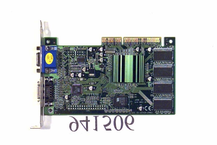
Click to zoom
Application Details
- Equipment Class
- JBP - Part 15 Class B Computing Device Peripheral
- Date of Grant
- Jun 14, 1999
- Application Purpose
- Original Equipment
- Date of Application
- May 10, 1999
- Company
- Gainward Co Ltd
- Country
- Taiwan
Documents & Files
Document Text
Text extracted from the exhibit documents filed with the FCC. Open a document above to read the original.
Users Manual
S3 Savage4 Multimedia VGA Controller FCC ID:ICUVGA-GW821 Installation Guide Version 1.0 04/99 Trademark Acknowledgments Microsoft is a trademark of Microsoft Corporation. All other brand and product names are trademarks or registered trademarks of their respective companies. MMMVS023-10E6RA FCC Notice This device complies with Part 15 of the FCC Rules. Operation is subject to the following two conditions:(1) this device may not cause harmful interference, and (2) this device must accept any interference received, including interference that may cause undesired operation. NOTE This equipment has been tested and found to comply with the limits for a Class B digital device, pursuant to Part 15 of the FCC Rules. These limits are designed to provide reasonable protection. This equipment generates, uses and can radiated radio frequency energy and, if not installed and used in accordance with the instructions, may cause harmful interference to radio communications. However, there is no guarantee that interference will not occur in a particular installation If this equipment does cause harmful interference to radio or television reception, which can be determined by turning the equipment off and on, the user is encouraged to try to correct the interference by one or more of the following measures: -Reorient o relocate the receiving antenna. -Increase the separation between the equipment and receiver. -Connect the equipment into an outlet on a circuit different from that to which the receiver is connected. -Consult the dealer or an experienced radio/TV technician for help. Shielded interface cables must be used in order to comply with emission limits. Changes or modifications not expressly approved by the party responsible for compliance could void the user‘s authority to operate the equipment. Table of Contents Chapter 1 Overview ........................................................ 1 Chapter 2 Hardware Installation .................................. 2 Chapter 3 Software Installation..................................... 4 Chapter 4 Display Properties for Windows ................... 5 Chapter 5 Expertool for Windows ................................. 7 Chapter 6 Technical Information ................................ 10 Chapter 7 Trouble Shooting......................................... 12
Users Manual
1 Congratulation on the purchase of your VGA board! You are now the owner of a state-of-the-art video adapter that offers features and functionality equal to, and beyond any other in the VGA class. System Requirements The minimum system requirements for installing the graphics card are as follows: ! a personal computer with a Pentium, Pentium II or compatible microprocessor and at least 8MB of memory ! a VGA analog monitor supporting a minimum 60Hz vertical refresh rate ! a free AGP bus slot ! a CD-ROM drive Features ! 128-bit S3 Savage4 3D/2D/Video Graphics Accelerator ! 8/16/32 MB SDRAM Display Memory ! Full 2X/4X AGP @ 4X Speed & Bandwidth (4X AGP function is Savage4 chip dependent) ! Flat Panel Desktop Monitor Support (Flat Panel monitor dependent) ! Hardware DVD Motion Compensation Support for DVD playback ! Integrated 300MHz RAMDAC with Gamma Correction ! 8M Triangles/second Floating Point Triangle Setup Engine ! 140M Pixels/sec Trilinear Fill Rate and Brightness, Hue, and Saturation Controls ! Microsoft DX6.X & S3 S3TC Texture Compression ! Single Cycle Trilinear Filtering ! Sprite Anti-Aliasing, Reflection Mapping, Texture Morphing, Shadows, Procedural Textures and Atmospheric Effects ! High Quality Up/Down Scalar and Maximum Resolution 1600x1200 ! Full Featured 2D Engine for Acceleration of BitBLT, Rectangle Fill, Panning/Scrolling and Hardware Cursor ! Hardware Support for Individually scalable Dual Video Windows ! 60MHz VIP Video Port Allows HDTV Resolutions ! Full Hardware and BIOS Support for VESA Timings and DDC " To execute the Savage4 with 4X AGP mode that was depended on the main board which can support the 4X AGP mode. It is automatic to detect the main board AGP mode and execute in 2X or 4X. Software Support ! Windows 9X ! Windows NT ! Windows DirectX ! OpenGL ICD 1 Overview 2 Before You Begin Before you process further, make sure your computer system meets the peripheral requirements and switch to the standard VGA display driver. Prepare Your Computer for Installation Prior to working on your computer, make sure the power of the computer and any related equipment is turned off. Select a Vacant Expansion PCI (AGP) Slot Most AGP (PCI) bus computers have a combination of AGP (PCI) and ISA expansion slots. AGP (PCI) are usually made with plastic of a contrasting brown color (beige color), and are shorter than other slots in your computer. Your system manual should identify the AGP (PCI) slots. Plugging your Graphic card into a non-AGP (PCI) slot could damage the card, your computer, or both. 2 Hardware Installation Static electricity can severely damage electronic parts. Take these precautions: ! Before touching any electronic parts, drain the static electricity from your body. You can do this by touching the internal metal frame of your computer while it's unplugged. ! Don't remove a card from the anti-static container it shipped in until you're ready to install it. When you remove a card from your computer, place it back in its container. ! Don't let your clothes touch any electronic parts. ! When handling a card, hold it by its edges, and avoid touching its circuitry. CAUTION ! Back of computer ISA slot PCI slot AGP slot AGP vs. PCI vs. ISA expansion slots 3 Insert your Graphic Card Remove the cover for the slot you intend to use and save the screw for the mounting bracket. Then, pick up the Graphic card and position it over the expansion slot you've chosen. Push the card with firmly and evenly until it's fully seated in the slot. Replace the screw to secure the bracket of the Graphic card to the computer chassis. Connect the monitor Plug your monitor cable into the monitor connector on your Graphic card. Make sure the other end of the monitor cable is properly connected to your monitor. DFP Host Receptacle Connector 2 Hardware Installation PCI expansion slot Graphics card Bracket screw Motherboard Monitor connector (blue) AGP expansion slot 4 " Before installing the Display driver, make sure your Windows 95/98/NT is installed in VGA mode and work fine. " For Windows 95 system, please install the DirectX before you want to play the MPEG Movie Player. " To use an AGP graphics card with NT4.0, you may need to pre-install NT with Service Pack 3 (SP3) or latter version before installing the AGP card. " If you are running Windows NT4.0, please note that some drivers are not compatible with earlier releases of Windows NT. Consult your dealer or local support to ensure you have the most recent releases for Windows NT and the drivers. Before You Begin If your system is running Windows 95/98/NT, the New Hardware Found dialog box will appear after restart. Select Driver from disk provided by hardware manufacturer , click OK , then follow all on-screen instructions. If the New Hardware Found dialog box does not appear, follow the instructions below. Setup VGA Mode Click the right mouse button anywhere on the Windows 95/98/NT desktop and select Properties from the pop-up menu that appears on screen. Select Settings | Change Display Ty pe (For OSR2 users, please select Settings │ Advanced Properties. For Windows 98 users, please select Settings │ Advanced. For Windows NT users, please select Setting │ Display Type ) and then click the [Change] button for Adapter Type. When the Select Device dialog box appears on the screen, please select [Standard display types] from the manufactures and select Standard Display Adapter (VGA) from the Models then click OK button. Install Software Driver 1. Turn on your computer and start Windows 95/98/NT. 2. Insert the Driver CD into your CD-ROM driver. 3. Click the Start button on the task bar and then select Run button. 4. Type D:\ Cdssetup.exe [ Enter ] in the Run dialog box (where D:\ is the location of your CD-ROM drive). 5. The Expertool VGA Installation dialog box will appear on the screen, please click "Continue" button and follow the instruction on screen to complete installation. 6. Final, restart your computer for the changes to take effe…
Text truncated - open the document above for the full version.
External Photos
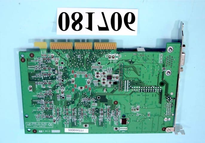
FCC ID : ICUVGA-GW821Front side of EUT Number 1 941506-1.JPG FCC ID : ICUVGA-GW821Rear side of EUT Number 2 941506-2.JPG
ID Label/Location Info
EXHIBIT A. FCC ID LABEL FCC ID:ICUVGA-GW821 The following statement will be placed in the User’s Manual. This device complies with Part 15 of the FCC Rules. Operation is subject to the following two conditions :(1) this device may not cause harmful interference, and (2) this device must accept any interference received, including interference that may cause undesired operation.
ID Label/Location Info
FCC ID LOCATION
Test Report
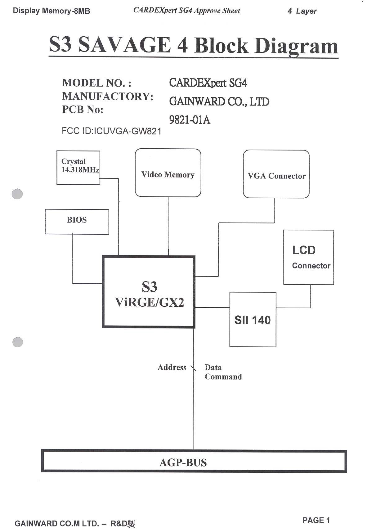
FCC TEST REPORT REPORT NO. : F941506 SPORTON International Inc. FCC ID : ICUVGA-GW821 TEL : 886-2-2696-2468PAGE NUMBER : 1 OF 31 FAX : 886-2-2696-2255ISSUED DATE: Apr. 22, 1999 FCC TEST REPORT for CISPR PUB. 22 CLASS B EQUIPMENT : CARDEXpert SG4 MODEL NO.: 9821-01A FCC ID : ICUVGA-GW821 FILING TYPE : Original Grant APPLICANT: GAINWARD CO., LTD. 12F,#96,Hsin Tai Wu Rd. Sec.1,His-chih, Taipei Hsien, Taiwan ! The test result refers exclusively to the test presented test model / sample. ! Without the written authorization of the test lab., the Test Report may not be copied. ! Certificate or Test Report must not be used by the applicant to claim the product in this test report endorsement by NVLAP or any agency of U.S. government. SPORTON INTERNATIONAL INC. 6F, No. 106, Hsin Tai Wu Rd., Sec. 1, Hsi Chih, Taipei Hsien, Taiwan, R.O.C. FCC TEST REPORT REPORT NO. : F941506 SPORTON International Inc. FCC ID : ICUVGA-GW821 TEL : 886-2-2696-2468PAGE NUMBER : 2 OF 31 FAX : 886-2-2696-2255ISSUED DATE: Apr. 22, 1999 FCC TEST REPORT REPORT NO. : F941506 SPORTON International Inc. FCC ID : ICUVGA-GW821 TEL : 886-2-2696-2468PAGE NUMBER : 3 OF 31 FAX : 886-2-2696-2255ISSUED DATE: Apr. 22, 1999 TABLE OF CONTENT SECTION TITLEPAGE CERTIFICATE OF COMPLIANCE ............................................................................................................................... 4 1. GENERAL DESCRIPTION OF EQUIPMENT UNDER TEST................................................................................ 5 1.1. APPLICANT ......................................................................................................................................................................................................... 5 1.2. MANUFACTURER : ............................................................................................................................................................................................ 5 1.3. BASIC DESCRIPTION OF EQUIPMENT UNDER TEST................................................................................................................................... 5 1.4. FEATURE OF EQUIPMENT UNDER TEST....................................................................................................................................................... 5 2. TEST CONFIGURATION OF EQUIPMENT UNDER TEST ..................................................................................6 2.1. TEST MANNER ................................................................................................................................................................................................... 6 2.2. DESCRIPTION OF TEST SYSTEM..................................................................................................................................................................... 6 2.3. CONNECTION DIAGRAM OF TEST SYSTEM ................................................................................................................................................. 8 3. TEST SOFTWARE ........................................................................................................................................................ 9 4. GENERAL INFORMATION OF TEST .................................................................................................................... 10 4.1. TEST FACILITY ................................................................................................................................................................................................. 10 4.2. STANDARD FOR METHODS OF MEASUREMENT ...................................................................................................................................... 10 4.3 .TEST IN COMPLIANCE WITH ......................................................................................................................................................................... 10 4.4. FREQUENCY RANGE INVESTIGATED.......................................................................................................................................................... 10 4.5. TEST DISTANCE ............................................................................................................................................................................................... 10 5. TEST OF CONDUCTED POWERLINE ................................................................................................................... 11 5.1. MAJOR MEASURING INSTRUMENTS ........................................................................................................................................................... 11 5.2. TEST PROCEDURES......................................................................................................................................................................................... 12 5.3. TYPICAL TEST SETUP LAYOUT OF CONDUCTED POWERLINE.............................................................................................................. 13 5.4. TEST RESULT OF AC POWERLINE CONDUCTED EMISSION ................................................................................................................... 14 5.5. PHOTOGRAPHS OF CONDUCTED POWERLINE TEST CONFIGURATION............................................................................................... 18 6. TEST OF RADIATED EMISSION ............................................................................................................................ 22 6.1. MAJOR MEASURING INSTRUMENTS ........................................................................................................................................................... 22 6.2. TEST PROCEDURES......................................................................................................................................................................................... 23 6.3. TYPICAL TEST SETUP LA…
Text truncated - open the document above for the full version.
Contact Information
Applicant
Po Chang(Assistant General Manager)
886 2 2696-6577Fax: 886 2 2696-6550
Technical Contact
SPORTON INTERNATIONAL INC.Kathy Lin
[email protected]886-2-2696-2468
6F, No. 106, Sec. 1, Hsin Tai Wu Rd., Hsi Chin, · Taiwan
Non-Technical Contact
SPORTON INTERNATIONAL INC.Kathy Lin
[email protected]718-468-4260
Test Firm
Sporton International Inc.W. Huang
Technical Specifications
| # | Rule Parts | Frequency Range | Power Output |
|---|---|---|---|
| 1 | 15B | - | - |
Other Applications from Gainward Co Ltd
ICUVGA-GWV05
Oct 16, 2000VGA Card
Equipment Class
JBP - Part 15 Class B Computing Device Peripheral
ICUVGA-GWV06
Oct 10, 2000VGA Card
Equipment Class
JBP - Part 15 Class B Computing Device Peripheral
ICUVGA-GWV03
Jul 30, 2000VGA CARD
Equipment Class
JBP - Part 15 Class B Computing Device Peripheral
ICUVGA-GWV02
May 30, 2000VGA CARD
Equipment Class
JBP - Part 15 Class B Computing Device Peripheral
ICUVGA-GWVZBA
Apr 19, 2000VGA CARD
Equipment Class
JBP - Part 15 Class B Computing Device Peripheral