ICUVGA-GWVZBAVGA CARD
Gainward Co Ltd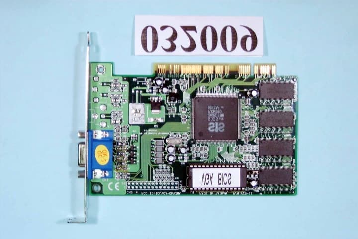
Click to zoom
Application Details
- Equipment Class
- JBP - Part 15 Class B Computing Device Peripheral
- Date of Grant
- Apr 19, 2000
- Application Purpose
- Original Equipment
- Date of Application
- Apr 05, 2000
- Equipment Note
- VGA CARD
- Company
- Gainward Co Ltd
- Country
- Taiwan
Documents & Files
Document Text
Text extracted from the exhibit documents filed with the FCC. Open a document above to read the original.
Users Manual
SiS 6326 Multimedia VGA Controller Installation Guide Version 1.0 03/98 Trademark Acknowledgments Microsoft is a trademark of Microsoft Corporation. AutoCAD, Autoshade and ADI are trademarks of Autodesk, Inc. SiS is a registered trademark of Silicon Integrated Systems Corp. All other brand and product names are trademarks or registered trademarks of their respective companies. MMMV4002-10E6RN FCC Notice This device complies with Part 15 of the FCC Rules. Operation is subject to the following two conditions: (1) this device may not cause harmful interference. (2) this device must accept any interference received, including interference that may cause undesired operation. Notice : This equipment has been tested and found to comply with the limits for a Class B digital device, pursuant to Part 15 of the FCC Rules. These limits are designed to provide reasonable protection against harmful interference in a residential installation. This equipment generates, uses, and can radiate radio frequency energy, and if not installed and used in accordance with manufacturer's instructions, may cause harmful interference to radio communications. However, there is no guarantee that interference will not occur in a particular installation. If this equipment does cause interference to radio or television reception, which can be determined by turning the equipment off and on, the user is encouraged to try to correct the interference by one or more of the following measures: . Reorient or relocate the receiving antenna. . Increase the separation between the equipment and receiver. . Plug the computer into a different outlet so that the two devices are on different branch circuits. . If necessary, the user should consult the dealer or an experienced radio/television technician for additional suggestions. Wa r ni n g : Shielded interface cables must be used in order to comply with emission limits. Changes or modifications not expressly approved by the party responsible for compliance could void the user's authority to operate the equipment. CSA Not ice : This digital apparatus does not exceed the Class B limits for radio noise emissions from digital apparatus set out in the Radio Interference Regulations of the Canadian Department of Communications. Table of Contents Chapter 1 Overview ..................................................... 1 Chapter 2 Hardware Installation ............................... 2 Chapter 3 Microsoft Windows 95/98 Drivers ............. 4 Chapter 4 Microsoft Windows NT Drivers................. 5 Chapter 5 Microsoft Windows 3.1 Drivers ................. 6 Chapter 6 Display Utility for Windows....................... 7 Chapter 7 AutoCAD R11 R12 Drivers...................... 9 Chapter 8 AutoShade R2.0 Drivers .......................... 10 Chapter 9 3D Studio Version 3.0 Drivers ..................11 Chapter 10 OS/2 Drivers........................................... 12 Chapter 11 Technical Information ........................... 13 Chapter 12 Trouble Shooting ................................... 14
Users Manual
Targeting the emerging PC market, SiS6326 is the first member of the new SiS63x6 family, w hich co nsists of high i ntegra tion, s uper perfor ma nce, and feature-rich 3D/2D grap hics & video accelerators. Being a 208-pin PQFP package, SiS6326 integrates AGP/PCI VGA controller, 3D/2D graphics accelerator, NTSC/PAL TV-OUT solution, MPEG-2/1 video decoder, and video accelerator. The target of SiS6326 is to meet all the emerging PC requirements which includes 3D acceleration, output to TV, DVD/VCD player, and video acceleration in one chip and in a market acceptable price. As the first member of 63x6 family, totally new pin-outs and application circuits are developed. However the definition of the registers are designed as backward compatible with previous SiS62x5 as possible as to shorten the product-to-market time. DRIVER SUPPORT ! Microsoft Windows NT3.5 ! Microsoft Windows NT4.0 ! Microsoft Windows 95 ! Microsoft Windows 3.1 ! AutoCAD/386 Release 11,12 ! AutoShade/386 Ver2.0 ! 3D Studio Ver3.0 1 1 Overview Before You Begin Before yo u process further, ma ke s ure yo ur co mp uter s yste m meets the peripheral requirements and switch to the standard VGA display driver. Prepare Your Computer for Installation Prior to working on your computer, make sure the power of the computer and any related equipment is turned off. Select a Vacant Expansion PCI (AGP) Slot Most AGP (PCI) bus computers have a combination of AGP (PCI) and ISA expansion slots. AGP (PCI) are usually made with plastic of a contrasting brown color (beige color), and are shorter than other slots in your computer. Your system manual should identify the AGP (PCI) slots. Plugging your Graphic card into a non-AGP (PCI) slot could damage the card, your computer, or both. 2 2 Hardware Installation Static electricity can severely damage electronic parts. Take these precautions: ! Before touching any electronic parts, drain the static electricity from your body. You can do this by touching the internal metal frame of your computer while it's unplugged. ! Don't remove a card from the anti-static container it shipped in until you're ready to install it. When you remove a card from your computer, place it back in its container. ! Don't let your clothes touch any electronic parts. ! When handling a card, hold it by its edges, and avoid touching its circuitry. CAUTION ! Back of computer ISA s lot PCI slot AGP slot AGP vs. PCI vs. ISA expansion slots Insert your Graphic Card Remove the cover for the slot you intend to use and save the screw for the mounting bracket. Then, pick up the Graphic card and position it over the expansion slot you've chosen. Push the card with firmly and evenly until it's fully seated in the slot. Replace the screw to secure the bracket of the Graphic card to the computer chassis. Connect the monitor Plug your monitor cable into the monitor connector on your Graphic card. Make sure the other end of the monitor cable is properly connected to your monitor. 3 2 Hardware Installation PCI expansion slot Graphics card Bracket screw Motherboard Mo nitor co nne ctor (blue ) AGP e xpansion slot SETUP VGA MODE Click the right mouse button anywhere on the Windows 95/98 desktop and select Properties from the pop-up menu that appears on screen. Select Settings | Change Display Type (If your are Win98 user please select Settings Adva nce d) and then click the [Change] button for Adapter Type. When the Select Device dialog box appears on the screen, please select [Standard display types] from the manufactures and select Standard Display Adapter (VGA) from the Models then click OK button. SETUP DRIVER 1. Turn on your computer and start Windows 95/98. 2. Insert the Driver CD into your CD-ROM driver. 3. Click the Start button on the task bar. 4. In Windows 95/98 "Start" screen, click Run Browse to select win95/98 driver source as D:\win95, D is the letter of your CD-ROM drive. 5. Select "Se tup.e xe" file, click "OK", then Win95/98 would perform driver installation. 6. After completing installation, Win95/98 would go back to "Restarting Windows" Screen, select "Ye s" icon (or "finis h" icon). And there are some items will be created after restarting. 4 ! Before installing the Display driver, make sure your Windows 95 is installed in VGA mode and work fine. ! Please install the DirectX before you want to play the MPEG Movie Player. ! If DirectDraw TM or Direct 3D TM has previously been installed on your system, the Windows 95 driver will ready to run after you finish the installation. If DirectDraw TM or Direct3D TM has not been installed, you will need to reboot your system again to initialize the driver. 3 Microsoft Windows 95/98 Drivers CAUTION ! If you are running Windows NT, please note that drivers for NT are not compatible with earlier releases of NT, and vice versa. Consult your dealer, local user support groups or on- line services from ti me to ti me to e ns ure yo u have the latest release for the version o f NT yo u are runni ng. To install the optimized display drivers for Windows NT, you must be running NT and follow Microsoft standard display driver installation procedure as documented in the NT user manual. Note the somewhat different installation procedures between NT and earlier release below. SETUP DRIVER 1. Turn on your computer and start Windows NT. 2. Insert the Driver CD into your CD-ROM driver, and select "My Computer" icon. 3. In "My Computer" Screen, select Co nt rol Pa ne l Dis play icon. 4. In "Display Properties" Screen, select "Settings" item. 5. In refreshed "Display Properties" Screen, select Display Ty pe Cha nge button in "Adapter Type". 6. In "Change Display" Screen, select [Have Disk] button and enter the path to the driver installation diskette. (e.g., D:\winnt\winnt40 or winnt35, D is the letter of your CD-ROM drive.) 7. In new Screen, "SiS 6326" would appear change display and select "OK". Then Win NT would perform driver installation. 8. After completing installation, Win NT would go back to…
Text truncated - open the document above for the full version.
Block Diagram
FCC ID : ICUVGA-GWVZBA
External Photos
FCC ID : ICUVGA-GWVZBA Number 1 032009-01.jpg FCC ID : ICUVGA-GWVZBA Number 2 032009-02.jpg
ID Label/Location Info
EXHIBIT A. FCC ID LABEL FCC ID:ICUVGA-GWVZBA The next page shows the location of FCC ID on EUT. The following statement will be placed in the User’s Manual. This device complies with Part 15 of the FCC Rules. Operation is subject to the following two conditions :(1) this device may not cause harmful interference, and (2) this device must accept any interference received, including interference that may cause undesired operation.
ID Label/Location Info
FCC ID LOCATION 9o2501-3f.JPG
Test Report
FCC TEST REPORT Report No. : F032009 SPORTON International Inc. FCC ID: IC UVG A- GWVZ BA TEL : 886-2-2696-2468Page No.: 1 of 24 FAX : 886-2-2696-2255Issued Date : Mar. 24, 2000 FCC TEST REPORT for CISPR PUB. 22 Class B Equipment: CARDEXpert 6326 (PCI) Model No.: VZB-12 FCC ID: ICUVGA-GWVZBA Filing Type: Original Grant Applicant: GAINWARD CO., LTD. 12F, No. 96, Hsin Tai Wu Rd., Sec. 1, Hsi-Chih, Taipei Hsien, Taiwan, R.O.C. ! The test result refers exclusively to the test presented test model / sample. ! Without the written authorization of the test lab., the Test Report may not be copied. ! Certificate or Test Report must not be used by the applicant to claim the product in this test report endorsement by NVLAP or any agency of U.S. government. SPORTON International Inc. 6F, No.106, Sec. 1, Hsin Tai Wu Rd., Hsi Chih, Taipei Hsien, Taiwan, R.O.C. FCC TEST REPORT Report No. : F032009 SPORTON International Inc. FCC ID: IC UVG A- GWVZ BA TEL : 886-2-2696-2468Page No.: 2 of 24 FAX : 886-2-2696-2255Issued Date : Mar. 24, 2000 Table of Contents CERTIFICATE OF COMPLIANCE .............................................................................................................. 3 1. General Description of Equipment under Test..................................................................................... 4 1.1. Applicant .............................................................................................................................................................................................................. 4 1.2. Manufac turer ....................................................................................................................................................................................................... 4 1.3. Basic Description of Equipme nt under Test................................................................................................................................................... 4 1.4. Feature of Eq uipment under Tes t.................................................................................................................................................................... 4 2. Test Configuration of Equipment under Test....................................................................................... 5 2.1. Test Ma nner ........................................................................................................................................................................................................ 5 2.2. Description of Test S ystem............................................................................................................................................................................... 5 2.3. Connec tion Diagram o f Test Sys tem .............................................................................................................................................................. 7 3. Test Software ....................................................................................................................................... 7 4. General Information of Test ................................................................................................................. 9 4.1. Test Facility ......................................................................................................................................................................................................... 9 4.2. Standard for Methods o f Meas ure ment .......................................................................................................................................................... 9 4.3. Test in Comp liance with .................................................................................................................................................................................... 9 4.4. Freque nc y Range Investigated ........................................................................................................................................................................ 9 4.5. Test Distance ...................................................................................................................................................................................................... 9 5. Test of Conducted Powerline............................................................................................................. 10 5.1. Major Measuring Instrume nts .........................................................................................................................................................................10 5.2. Test Procedures ...............................................................................................................................................................................................11 5.3. Typical Test Setup La yo ut o f Co nduc ted Powerline ...................................................................................................................................12 5.4. Test Res ult o f AC Powerline Cond ucted Emission.....................................................................................................................................13 5.5. Photograp hs o f Cound ucted Powerline Tes t Configura tion ......................................................................................................................15 6. Test of Radiated Emission.................................................................................................................. 17 6.1. Major Measuring Instrume nts .........................................................................................................................................................................17 6.2. Test Procedures ........................................................................................................................................................................................…
Text truncated - open the document above for the full version.
Contact Information
Applicant
Po Chang(Assistant General Manager)
886 2 2696-6577Fax: 886 2 2696-6550
Technical Contact
SPORTON International Inc.Kathy Lin
[email protected]886-2-26962468
6F, No. 106, Sec. 1, Hsin Tai Wu Rd., Hsi Chin, · Taipei Hsien · Taiwan
Non-Technical Contact
SPORTON International Inc.Kathy Lin
[email protected]718-468-4260
Test Firm
Sporton International Inc.W. Huang
Technical Specifications
| # | Rule Parts | Frequency Range | Power Output |
|---|---|---|---|
| 1 | 15B | - | - |
Other Applications from Gainward Co Ltd
ICUVGA-GWV05
Oct 16, 2000VGA Card
Equipment Class
JBP - Part 15 Class B Computing Device Peripheral
ICUVGA-GWV06
Oct 10, 2000VGA Card
Equipment Class
JBP - Part 15 Class B Computing Device Peripheral
ICUVGA-GWV03
Jul 30, 2000VGA CARD
Equipment Class
JBP - Part 15 Class B Computing Device Peripheral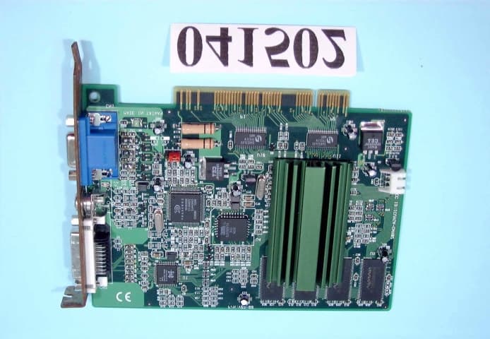
ICUVGA-GWV02
May 30, 2000VGA CARD
Equipment Class
JBP - Part 15 Class B Computing Device Peripheral
ICUVGA-GWVZHA
Apr 13, 2000VGA CARD
Equipment Class
JBP - Part 15 Class B Computing Device Peripheral