ICUVGA-GWV06VGA Card
Gainward Co Ltd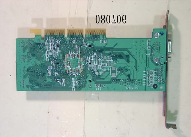
Click to zoom
Application Details
- Equipment Class
- JBP - Part 15 Class B Computing Device Peripheral
- Date of Grant
- Oct 10, 2000
- Application Purpose
- Original Equipment
- Date of Application
- Oct 10, 2000
- Equipment Note
- VGA Card
- Company
- Gainward Co Ltd
- Country
- Taiwan
Documents & Files
Document Text
Text extracted from the exhibit documents filed with the FCC. Open a document above to read the original.
Users Manual
nVIDIA GeForce 2 GTS Multimedia VGA Controller Installation Guide Version 1.0 06/2000 Copyrights and Liabilities The information contained in this manual has been validated at the time of this manual’s production. The manufacturer reserves the right to make any changes and improvements on the product described in this manual at any time and without notice. Consequently, the manufacturer assumes no liability for damages incurred directly or indirectly from errors, omissions or discrepancies between the product and the manual. All registered trademarks are the property of their respective owners. Copyright © 1999 All rights reserved. No reproduction of this document in any form is permitted without prior written authorization from the manufacturer. Trademark All products and company names are trademarks or registered trademarks of their respective holders. MM0GF2G-01E-00 FCC Notice This device complies with Part 15 of the FCC Rules. Operation is subject to the following two conditions: (1) This device may not cause harmful interference. (2) This device must accept any interference received, including interference that may cause undesired operation. Notice: This equipment has been tested and found to comply with the limits for a Class B digital device, pursuant to Part 15 of the FCC Rules. These limits are designed to provide reasonable protection against harmful interference in a residential installation. This equipment generates, uses, and can radiate radio frequency energy, and if not installed and used in accordance with manufacturer's instructions, may cause harmful interference to radio communications. However, there is no guarantee that interference will not occur in a particular installation. If this equipment does cause interference to radio or television reception, which can be determined by turning the equipment off and on, the user is encouraged to try to correct the interference by one or more of the following measures: . Reorient or relocate the receiving antenna. . Increase the separation between the equipment and receiver. . Plug the computer into a different outlet so that the two devices are on different branch circuits. . If necessary, the user should consult the dealer or an experienced radio/television technician for additional suggestions. Warning: Shielded interface cables must be used in order to comply with emission limits. Changes or modifications not expressly approved by the party responsible for compliance could void the user's authority to operate the equipment. CSA Notice: This digital apparatus does not exceed the Class B limits for radio noise emissions from digital apparatus set out in the Radio Interference Regulations of the Canadian Department of Communications. Table of Contents Chapter 1 Overview ..................................................................1 Chapter 2 Hardware Installation .............................................3 Chapter 3 Software Installation ...............................................5 Chapter 4 Display Properties for Windows..............................8 Chapter 5 Expertool for Windows..........................................13 Chapter 6 Technical Information ..........................................17 Chapter 7 Trouble Shooting...................................................19 1 Congratulation on the purchase of your new graphics accelerator card! You are now the owner of a state-of-the-art video adapter that offers features and functionality equal to, and beyond any other in its VGA class. System Requirements The minimum system requirements for installing the graphics card are as follows: ¾ a personal computer with a Pentium, Pentium II, Pentium III or compatible microprocessor and at least 8MB of memory ¾ a VGA analog monitor supporting a minimum 60Hz vertical refresh rate ¾ an available AGP or PCI bus slot ¾ a CD-ROM drive Features ¾ 256Bit Graphics architecture ¾ Support 2/4X AGP with Fast Write AND Execute mode ¾ Integrated 350MHz RAMDAC, resolution up to 2048x1536 True Color @75Hz ¾ Full acceleration for Microsoft DirectX7 and Open GL 1.2 ICD ¾ 2 nd generation T&L Engines ¾ 32-bit color & 32-bit Z/Stencil buffer ¾ Cube Environment Mapping ¾ 8 Texels Per Clock with Hypertexel ¾ Order Environment Mapping ¾ 25M Triagngles/sec through Set-up & 1600M texels/sec. ¾ DirectX Texture Compression ¾ Enhanced Motion compensation for full speed DVD playback ¾ Support DVI-I 1.0 Digital Flat Panel output (Optional) ¾ Support NTSC/PAL TV-OUT with flicker filter (Optional) ¾ S3TC Support ¾ Support Video In (Optional) ¾ Support VIP I/O port (Optional) High Performance 256-bit 2D Acceleration ¾ True-color hardware cursor ¾ Multi-buffering for smooth animation and video playback Chapter 1 Overview 2 Visually Stunning Interactive 3D ¾ 8 texture-mapped ,filtered ,lit texels per clock cycle ¾ 32-bit Z/stencil buffer (Floating point or integer) ¾ 32-bit ARGB rendering with destination alpha ¾ High Quality Texture Filtering, including Anisotropic ¾ Single pass multi-texture High Quality HDTV/DVD Playback ¾ 8:1 up scaling and down scaling ¾ Video acceleration for DirectShow, MPEG-1, MPEG-2 and Indeo ¾ Multiple Video windows with hardware color space conversion and filtering Software Support ¾ Microsoft Windows 95/98/2000 ¾ Microsoft Windows NT4.0 ¾ DirectDraw ¾ Direct3D Direct Video ¾ ActiveX 3 Back of computer Static electricity can severely damage electronic parts. Take these precautions: ) Before touching any electronic parts, drain the static electricity from your body. You can do this by touching the internal metal frame of your computer while it's unplugged. ) Don't remove a card from the anti-static container it shipped in until you're ready to install it. When you remove a card from your computer, place it back in its container. ) Don't let your clothes touch any electronic parts. ) When handling a card, hold it by its edges, and avoid touching its circuitry. Before You Begin Before you process further, make sure your com…
Text truncated - open the document above for the full version.
External Photos
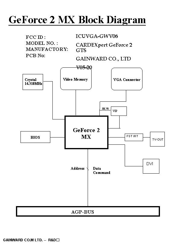
FCC ID : ICUVGA-GWV06Front side of EUT Number 1 FCC ID : ICUVGA-GWV06Rear side of EUT Number 2
ID Label/Location Info
FCC ID LOCATION
Internal Photos
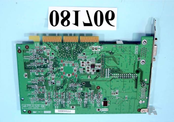
FCC ID : ICUVGA-GWV06Front side of EUT Number 1 FCC ID : ICUVGA-GWV06Rear side of EUT Number 2
Test Report
FCC TEST REPORT Report No. : F080706 SPORTON International Inc. FCC ID: ICUVGA-GWV06 TEL : 886-2-2696-2468Page No.: 1 of 24 FAX : 886-2-2696-2255Issued Date : Aug. 24, 2000 FCC TEST REPORT for 47 CFR, Part 2, Part 15 and CISPR PUB. 22 Class B Equipment: VGA CARD Model No.: V06-01 FCC ID: ICUVGA-GWV06 Filing Type: Original Grant Applicant: GAINWARD CO., LTD. 12F, #96, Hsin Tai Wu Rd., Sec. 1, Hsi-Chih, Taipei Hsien, Taiwan ! The test result refers exclusively to the test presented test model / sample. ! Without the written authorization of the test lab., the Test Report may not be copied. ! Certificate or Test Report must not be used by the applicant to claim the product in this test report endorsement by NVLAP or any agency of U.S. government. SPORTON International Inc. 6F, No.106, Sec. 1, Hsin Tai Wu Rd., Hsi Chih, Taipei Hsien, Taiwan, R.O.C. FCC TEST REPORT Report No. : F080706 SPORTON International Inc. FCC ID: ICUVGA-GWV06 TEL : 886-2-2696-2468Page No.: 2 of 24 FAX : 886-2-2696-2255Issued Date : Aug. 24, 2000 Table of Contents CERTIFICATE OF COMPLIANCE .............................................................................................................. 3 1. General Description of Equipment under Test..................................................................................... 4 1.1. Applicant .............................................................................................................................................................................................................. 4 1.2. Manufac turer ....................................................................................................................................................................................................... 4 1.3. Basic Description of Equipme nt under Test................................................................................................................................................... 4 1.4. Feature of Eq uipment under Tes t.................................................................................................................................................................... 4 2. Test Configuration of Equipment under Test....................................................................................... 5 2.1. Test Ma nner ........................................................................................................................................................................................................ 5 2.2. Description of Test S ystem............................................................................................................................................................................... 5 2.3. Connec tion Diagram o f Test Sys tem .............................................................................................................................................................. 7 3. Test Software ....................................................................................................................................... 8 4. General Information of Test ................................................................................................................. 9 4.1. Test Facility ......................................................................................................................................................................................................... 9 4.2. Standard for Methods o f Meas ure ment .......................................................................................................................................................... 9 4.3. Test in Comp liance with .................................................................................................................................................................................... 9 4.4. Freque nc y Range Investigated ........................................................................................................................................................................ 9 4.5. Test Distance ...................................................................................................................................................................................................... 9 5. Test of Conducted Powerline............................................................................................................. 10 5.1. Major Measuring Instrume nts .........................................................................................................................................................................10 5.2. Test Procedures ...............................................................................................................................................................................................11 5.3. Typical Test Setup La yo ut o f Co nduc ted Powerline ...................................................................................................................................12 5.4. Test Res ult o f AC Powerline Cond ucted Emission.....................................................................................................................................13 5.5. Photograp hs o f Cond uc ted Powerline Tes t Configuration.........................................................................................................................15 6. Test of Radiated Emission.................................................................................................................. 17 6.1. Major Measuring Instrume nts .........................................................................................................................................................................17 6.2. Test Procedures ..............................................................................................................................................................................................…
Text truncated - open the document above for the full version.
Test Setup Photos
1.1. Photographs of Radiated Emission Test Configuration ! The photographs show the configuration that generates the maximum emission. FRONT VIEW REAR VIEW
Test Setup Photos
1.1. Photographs of Conducted Powerline Test Configuration ! The photographs show the configuration that generates the maximum emission. FRONT VIEW REAR VIEW SIDE VIEW
Contact Information
Applicant
Po Chang(Assistant General Manager)
886 2 2696-6577Fax: 886 2 2696-6550
Test Firm
Sporton International Inc.W. Huang
Technical Specifications
| # | Rule Parts | Frequency Range | Power Output |
|---|---|---|---|
| 1 | 15B | - | - |
Other Applications from Gainward Co Ltd
ICUVGA-GWV05
Oct 16, 2000VGA Card
Equipment Class
JBP - Part 15 Class B Computing Device Peripheral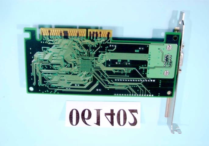
ICUVGA-GWV03
Jul 30, 2000VGA CARD
Equipment Class
JBP - Part 15 Class B Computing Device Peripheral
ICUVGA-GWV02
May 30, 2000VGA CARD
Equipment Class
JBP - Part 15 Class B Computing Device Peripheral
ICUVGA-GWVZBA
Apr 19, 2000VGA CARD
Equipment Class
JBP - Part 15 Class B Computing Device Peripheral
ICUVGA-GWVZHA
Apr 13, 2000VGA CARD
Equipment Class
JBP - Part 15 Class B Computing Device Peripheral