ICUVGA-GWVZHAVGA CARD
Gainward Co Ltd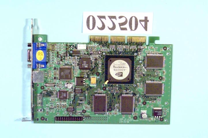
Click to zoom
Application Details
- Equipment Class
- JBP - Part 15 Class B Computing Device Peripheral
- Date of Grant
- Apr 13, 2000
- Application Purpose
- Original Equipment
- Date of Application
- Apr 04, 2000
- Equipment Note
- VGA CARD
- Company
- Gainward Co Ltd
- Country
- Taiwan
Documents & Files
Document Text
Text extracted from the exhibit documents filed with the FCC. Open a document above to read the original.
Users Manual
NVIDIA GeForce256 Multimedia VGA Controller Installation Guide Version 1.0 01/00 Copyrights and Liabilities The information contained in this manual has been validated at the time of this manual’s production. The manufacturer reserves the right to make any changes and improvements on the product described in this manual at any time and without notice. Consequently, the manufacturer assumes no liability for damages incurred directly or indirectly from errors, omissions or discrepancies between the product and the manual. All registered trademarks are the property of their respective owners. Copyright © 1999 All rights reserved. No reproduction of this document in any form is permitted without prior written authorization from the manufacturer. Trademark All products and company names are trademarks or registered trademarks of their respective holders. MMP0000-10E-0C FCC Notice This device complies with Part 15 of the FCC Rules. Operation is subject to the following two conditions: (1) This device may not cause harmful interference. (2) This device must accept any interference received, including interference that may cause undesired operation. Notice: This equipment has been tested and found to comply with the limits for a Class B digital device, pursuant to Part 15 of the FCC Rules. These limits are designed to provide reasonable protection against harmful interference in a residential installation. This equipment generates, uses, and can radiate radio frequency energy, and if not installed and used in accordance with manufacturer's instructions, may cause harmful interference to radio communications. However, there is no guarantee that interference will not occur in a particular installation. If this equipment does cause interference to radio or television reception, which can be determined by turning the equipment off and on, the user is encouraged to try to correct the interference by one or more of the following measures: . Reorient or relocate the receiving antenna. . Increase the separation between the equipment and receiver. . Plug the computer into a different outlet so that the two devices are on different branch circuits. . If necessary, the user should consult the dealer or an experienced radio/television technician for additional suggestions. Warn i n g: Shielded interface cables (except TV cable) must be used in order to comply with emission limits. Changes or modifications not expressly approved by the party responsible for compliance could void the user's authority to operate the equipment. Attention: This product, FCC ID:ICUVGA-GWVZHA, only be certified with Monitor connector and TV-out S-video jack. The user should disregard any information in the manual about other connectors. CSA Notice: This digital apparatus does not exceed the Class B limits for radio noise emissions from digital apparatus set out in the Radio Interference Regulations of the Canadian Department of Communications. Table of Contents Chapter 1 Overview................................................................... 1 Chapter 2 Hardware Installation ............................................. 2 Chapter 3 Software Installation ............................................... 4 Chapter 4 Display Properties for Windows.............................. 6 Chapter 5 Expertool for Windows .......................................... 11 Chapter 6 Technical Information........................................... 15 Chapter 7 Trouble Shooting ................................................... 19
Users Manual
1 Congratulation on the purchase of your new graphics accelerator card! You are now the owner of a state-of-the-art video adapter that offers features and functionality equal to, and beyond any other in its VGA class. System Requirements The minimum system requirements for installing the graphics card are as follows: ! a personal computer with a Pentium, Pentium II, Pentium III or compatible microprocessor and at least 8MB of memory ! a VGA analog monitor supporting a minimum 60Hz vertical refresh rate ! an available AGP or PCI bus slot ! a CD-ROM drive Features ! NVIDIA 256Bit High Performance GeForce256 GPU. ! Integrated Transform and Lighting (T&L). ! Support 32/64MB SDR/DDR Video Memory (Optional). ! Support TV out and DVI Interface for LCD Panel (Optional). ! 350MHz RAMDAC, Max. Resolution support 2048x1536. ! Single-Chip GPU (Graphics Processing Unit). ! 15 million polygons per second. ! 480 million pixels per second. ! Independent Pipelined QuadEngine. ! AGP 4X with Fast Writes. ! High-Quality HDTV Processor. ! 256-Bit 2D Rendering Engine. Software Support ! Microsoft Windows 95/98/2000 ! Microsoft Windows NT4.0 ! DirectX7.0 above ! OpenGL ICD ! OS/2 Static electricity can severely damage electronic parts. Take these precautions: " Before touching any electronic parts, drain the static electricity from your body. You can do this by touching the internal metal frame of your computer while Chapter 1 OverviewChapter 2 Hardware Installation 2 Back of computer it's unplugged. " Don't remove a card from the anti-static container it shipped in until you're ready to install it. When you remove a card from your computer, place it back in its container. " Don't let your clothes touch any electronic parts. " When handling a card, hold it by its edges, and avoid touching its circuitry. Before You Begin Before you process further, make sure your computer system meets the peripheral requirements and switch to the standard VGA display driver. Prepare Your Computer for Installation Prior to working on your computer, make sure the power of the computer and any related equipment is turned off. Select a Vacant Expansion AGP (PCI) Slot Most computers have a combination of AGP, PCI and ISA expansion slots. AGP slots are usually made from plastic of a contrasting brown color (beige color), and are shorter than other slots in your computer. Your system manual should identify the AGP or PCI slots, as appropriate for your model. Plugging your Graphic card into an incorrect slot could damage the card, your computer, or both. Do not try to force a card into a slot that does not accommodate it, as it is probably the wrong slot. Insert your Graphic Card Remove the cover for the slot you intend to use and save the screw for the mounting bracket. Then, pick up the Graphic card and position it over the expansion slot you’ve chosen. Push the card with firmly and evenly until it’s fully seated in the slot. Replace the screw to secure the bracket of the Graphic card to the computer chassis. ISA slot PCI slot AGP vs. PCI vs. ISA expansion slots PCI expansion slot Graphics card Bracket screw Mhb d AGP expansion slot AGP slot 3 Connect the monitor/LCD Connect the Monitor/DVI/TV Plug your monitor/DVI/TV cable into the monitor/DVI/TV connector on your Graphic card. Make sure the other end of the monitor/DVI/TV cable is properly connected to your monitor/DVI/TV. " Before installing the Display driver, make sure your Windows 95/98/NT was installed in VGA mode and functions properly. " For Windows 95 systems, please install DirectX before attempting to use the MPEG Movie Player. " To use an AGP graphics card with NT4.0, you may need to re-install NT with Service Pack 3 (SP3) or later version before installing the AGP card. " If you are running Windows NT4.0, please note that some drivers are not compatible with earlier releases of Windows NT. Consult your dealer or local support to ensure you have the most recent releases for Windows NT and the drivers. Before You Begin If your system is running Windows 95/98/NT, the New Hardware Found dialog box will appear after restart. Select Driver from disk provided by hardware manufacturer, click OK, then follow all on-screen instructions. If the New Monitor Connector (Blue)DVI Host Receptacle Connector Chapter 3 Software Installation TV-Out CompositeTV-Out S-Video 4 Hardware Found dialog box does not appear, follow the instructions below. Setup VGA Mode Click the right mouse button anywhere on the Windows 95/98/NT desktop and select Properties from the pop-up menu that appears on screen. Select Settings Change Display Type (For OSR2 users, please select Settings Advanced Properties. For Windows 98 users, please select Settings Advanced. For Windows NT users, please select Setting Display Type) and then click the [Change] button for Adapter Type. When the Select Device dialog box appears on the screen, please select [Standard display types] from the manufacturers list and select Standard Display Adapter (VGA) from the list of models then click OK. Install Software Driver 1. Turn on your computer and start Windows 95/98/NT. 2. Ins ert the Driver CD into your CD-ROM drive. 3. Click the Start button on the task bar and then select Run button. 4. Typ e D: \Cdsetup.exe [Enter] in the Run dialog box (where D:\ is the location of your CD-ROM drive). 5. Th e Expertool VGA Installation dialog box will appear on the screen, please click “Continue” button and follow the instructions on screen to complete installation. 6. Final, restart your computer to allow the changes to take effect. Windows 95/98/NT Display Properties Windows 95/98/NT allows you to select resolution, color depth, refresh frequency and font size using the standard Windows 95/98/NT Display Properties screen, which can be accessed by right clicking anywhere on the Windows 95/98/NT desktop, and then selecting Properties from the pop-up menu that appears on screen. 5 These pictures in this chapter are only for Win98 reference.…
Text truncated - open the document above for the full version.
Users Manual
12 Figure 5-4 Figure 5-5 (As Figure 5-4) DeskTop: Displays the current Resolution Setting, Color Setting, Font Size and Refresh Rate for the monitor. Drag the slider to specify values for each setting and click OK to put changes into effect. (As Figure 5-5) Information: Displays the current display settings and information of your computer. Run this program each time Windows starts - check box: Select this option to run Expertool immediately each time Windows starts. Figure 5-6 Figure 5-7 (As Figure 5-6) 13 Screen Adjustment: Selects Adjust to adjust the screen position with the keyboard. If you wish to cancel any changes you’ve made, select Default. Monitor Information: Shows information about your monitor. Hide modes that this monitor cannot display: Unchecking this box will allow you to set your display to modes that this monitor cannot display correctly. This may lead to an unusable display and/or damaged hardware. Power Saving: Allows you to adjust the Power Saving settings for Standby, Suspend or Shut-off mode. Standby check box: This option instantly places your monitor in standby mode, which delivers minimal power savings but provides optimal recovery time. Suspend check box: This option instantly places your monitor in Suspend mode, which delivers maximum savings but requires a somewhat longer recovery time than Standby mode. Shut-off check box: This option effectively turns your monitor off, and recovery time is practically equivalent to turning the monitor on using the monitor's power switch. (As Figure 5-7) Color: Moves the slider to adjust the gamma value. The farther you slide this to the right, the higher the gamma value, and the brighter your display will be. The more you slide this to the left, the lower the gamma value, and the dimmer your display will be. Figure 5-8 Figure 5-9 (As Figure 5-8) Memory/Core Clock Setting Slider Control: Allows you to adjust your video memory/core clock for peek performance and maximum stability. The higher you set the memory/core clock the greater the performance increase. But changing this value 14 will affect the stability of the VGA card. It is recommended that you use the original setting. (As Figure 5-9) DirectX: DirectX properties vary depending on the version of windows you are running, the version of DirectX installed, and the type of DirectX enabled drivers installed. This dialog box will also display the system's DirectX capabilities, and related information. Figure 5-10 (As Figure 5-10) Zoom In: Clicks on the client area and drags the mouse to zoom the desktop. (As Figure 5-2) Minimize: Close the menu and minimizes this application. Close: Close this application and disables the features it supports. Display Memory Configuration Memory-Resolution/Color The table below is for reference only. 256 color16bit32bit Chapter 6 Technical Information 15 640x480 120Hz120Hz120Hz 800x600 120Hz120Hz120Hz 1024x768 120Hz120Hz120Hz 1152x864 100Hz100Hz100Hz 1280x960 85Hz85Hz85Hz 1280x1024 85Hz85Hz85Hz 1600x900 100Hz100Hz100Hz 1600x1200 75Hz75Hz75Hz Monitor Connector Pin Assignments Pin no. Function Pin no. Function 1Red Video 9 +5V 2Green Video 10 Sync Return (ground) 3Blue Video 11 NC 4NC 12 DDC DATA 5Ground 13 Horizontal Sync 6Red Return (ground) 14 Vertical Sync 7Green Return (ground) 15 DDC CLOCK 8 Blue Return (ground) 16 DVI Connector Pin Assignments and Description Pin no. Signal Name Description 1 TX2-TMDS negative differential output, channel 2 2TX2+TMDS positive differential output, channel 2 3SHLD2/4Shield for TMDS channel 2/4 4TX4- TMDS negative differential output, channel 4 5TX4+ TMDS positive differential output, channel 4 6DDC_CLKDDC2B Clock 7DDC_DATDDC2B Data 8Vertical SyncSignal for the analog interface 9TX1- TMDS negative differential output, channel 1 10TX1+ TMDS positive differential output, channel 1 11SHLD1/3Shield for TMDS channel 1/3 12TX3-TMDS negative differential output, channel 3 13 TX3+TMDS positive differential output, channel 3 14+5V PowerLogic +5V supply 15GroundGround reference for +5 volt power pin. Used as return by Hsync and Vsync Signals 16HPDSignal is driven by monitor to enable the system to identify the presence of a monitor. 17 TX0- TMDS negative differential output, channel 0 18TX0+ TMDS positive differential output, channel 0 19 SHLD0/5 Shield for TMDS channel 0/5 20TX5- TMDS negative differential output, channel 5 21TX5+ TMDS positive differential output, channel 5 22SHLD Clock Shield for TMDS clock differential pair 23TXC+ TMDS positive differential output, channel Clock 24TXC- TMDS negative differential output, channel Clock VESA VGA Mode Table ModePixelsColorsWindowedLinear 17 (hex) 100h640 by 400256VV 101h640 by 480256VV 102h800 by 60016VV 103h800 by 600256VV 104h1024 by 76816VV 105h1024 by 768256VV 106h1280 by 102416VV 107h1280 by 1024256VV 108h80 by 6016VV 109h132 by 2516VV 10a132 by 4316VV 10b132 by 5016VV 10c132 by 6016VV 10e320 by 200256VV 10f320 by 20064KVV 111640 by 48032KVV 112640 by 48064KVV 114800 by 60032KVV 115800 by 60064KVV 1171024 by 76832KVV 1181024 by 76864KVV 11a1280 by 102432KVV 130320 by 200256VV 131320 by 400256VV 132320 by 40032KVV 133320 by 40064KVV 134320 by 240256VV 135320 by 24032KVV 136320 by 24064KVV 13d640 by 40032KVV 13e640 by 40064KVV 1451600 by 1200256VV 1461600 by 120032KVV 2D Memory Configurations 18 Memory Configuration WidthHeightColor 16MB32MB 6404808-bitVV 64048016-bitVV 64048032-bitVV 8006008-bitVV 80060016-bitVV 80060032-bitVV 10247688-bitVV 102476816-bitVV 102476832-bitVV 11528648-bitVV 115286416-bitVV 115286432-bitVV 12809608-bitVV 128096016-bitVV 128096032-bitVV 128010248-bitVV 1280102416-bitVV 1280102432-bitVV 16009008-bitVV 160090016-bitVV 160090032-bitVV 160012008-bitVV 1600120016-bitVV 1600120032-bitVV 19 Problem: After installation and restarting, Windows 95 informs me that display settings are still incorrect. There may be conflict between previous and current display drivers. This is caused by incomplete removal of previous display driv…
Text truncated - open the document above for the full version.
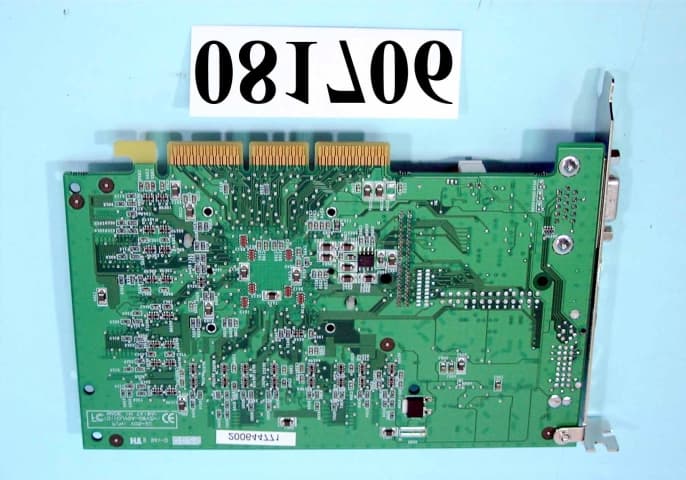
External Photos
FCC ID : ICUVGA-GWVZHA Number 1 022504-01.jpg FCC ID : ICUVGA-GWVZHA Number 2 022504-02.jpg FCC ID : ICUVGA-GWVZHA Number 3 022504-03.jpg
ID Label/Location Info
EXHIBIT A. FCC ID LABEL FCC ID:ICUVGA-GWVZHA The next page shows the location of FCC ID on EUT. The following statement will be placed in the User’s Manual. This device complies with Part 15 of the FCC Rules. Operation is subject to the following two conditions :(1) this device may not cause harmful interference, and (2) this device must accept any interference received, including interference that may cause undesired operation.
ID Label/Location Info
FCC ID LOCATION
Test Report
FCC TEST REPORT Report No. : F022504 SPORTON International Inc. FCC ID: IC UV GA - TEL : 886-2-2696-2468Page No.: 1 of 29 FAX : 886-2-2696-2255Issued Date : Mar. 10, 2000 FCC TEST REPORT for CISPR PUB. 22 Class B Equipment: CARDEXpert GeForce 256 Model No.: VZH-00 FCC ID: ICUVGA-GWVZHA Filing Type: Original Grant Applicant: GAINWARD CO., LTD. 12F, No. 96, Hsin Tai Wu Rd., Sec. 1, Hsi-Chih, Taipei Hsien, Taiwan, R.O.C. ! The test result refers exclusively to the test presented test model / sample. ! Without the written authorization of the test lab., the Test Report may not be copied. ! Certificate or Test Report must not be used by the applicant to claim the product in this test report endorsement by NVLAP or any agency of U.S. government. SPORTON International Inc. 6F, No.106, Sec. 1, Hsin Tai Wu Rd., Hsi Chih, Taipei Hsien, Taiwan, R.O.C. FCC TEST REPORT Report No. : F022504 SPORTON International Inc. FCC ID: IC UV GA - TEL : 886-2-2696-2468Page No.: 2 of 29 FAX : 886-2-2696-2255Issued Date : Mar. 10, 2000 Table of Contents CERTIFICATE OF COMPLIANCE.............................................................................................................. 3 1. General Description of Equipment under Test..................................................................................... 4 1.1. Applicant.............................................................................................................................................................................................................. 4 1.2. Manufacturer....................................................................................................................................................................................................... 4 1.3. Basic Description of Equipment under Test................................................................................................................................................... 4 1.4. Feature of Equipment under Test.................................................................................................................................................................... 4 2. Test Configuration of Equipment under Test....................................................................................... 5 2.1. Test Manner........................................................................................................................................................................................................ 5 2.2. Description of Test System............................................................................................................................................................................... 5 2.3. Connection Diagram of Test System.............................................................................................................................................................. 7 3. Test Software....................................................................................................................................... 8 4. General Information of Test................................................................................................................. 9 4.1. Test Facility......................................................................................................................................................................................................... 9 4.2. Standard for Methods of Measurement.......................................................................................................................................................... 9 4.3. Test in Compliance with.................................................................................................................................................................................... 9 4.4. Frequency Range Investigated........................................................................................................................................................................ 9 4.5. Test Distance...................................................................................................................................................................................................... 9 5. Test of Conducted Powerline............................................................................................................. 10 5.1. Major Measuring Instruments.........................................................................................................................................................................10 5.2. Test Procedures...............................................................................................................................................................................................11 5.3. Typical Test Setup Layout of Conducted Powerline...................................................................................................................................12 5.4. Test Result of AC Powerline Conducted Emission.....................................................................................................................................13 5.5. Photographs of Counducted Powerline Test Configuration......................................................................................................................16 6. Test of Radiated Emission.................................................................................................................. 20 6.1. Major Measuring Instruments.........................................................................................................................................................................20 6.2. Test Procedures...............................................................................................................................................................................................21 6.3. Typical Test Setup Layout of Radiated Emission…
Text truncated - open the document above for the full version.
Contact Information
Applicant
Po Chang(Assistant General Manager)
886 2 2696-6577Fax: 886 2 2696-6550
Technical Contact
SPORTON International Inc.Kathy Lin
[email protected]886-2-26962468
6F, No. 106, Sec. 1, Hsin Tai Wu Rd., Hsi Chin, · Taipei Hsien · Taiwan
Non-Technical Contact
SPORTON International Inc.Kathy Lin
[email protected]718-468-4260
Test Firm
Sporton International Inc.W. Huang
Technical Specifications
| # | Rule Parts | Frequency Range | Power Output |
|---|---|---|---|
| 1 | 15B | - | - |
Other Applications from Gainward Co Ltd
ICUVGA-GWV05
Oct 16, 2000VGA Card
Equipment Class
JBP - Part 15 Class B Computing Device Peripheral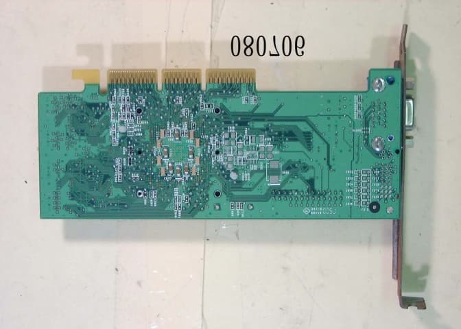
ICUVGA-GWV06
Oct 10, 2000VGA Card
Equipment Class
JBP - Part 15 Class B Computing Device Peripheral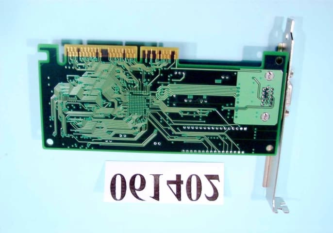
ICUVGA-GWV03
Jul 30, 2000VGA CARD
Equipment Class
JBP - Part 15 Class B Computing Device Peripheral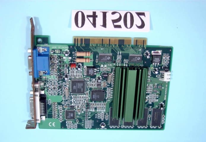
ICUVGA-GWV02
May 30, 2000VGA CARD
Equipment Class
JBP - Part 15 Class B Computing Device Peripheral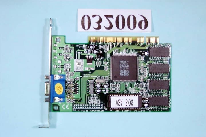
ICUVGA-GWVZBA
Apr 19, 2000VGA CARD
Equipment Class
JBP - Part 15 Class B Computing Device Peripheral