IGKHP106ALocator Hub
Nielsen Audio Inc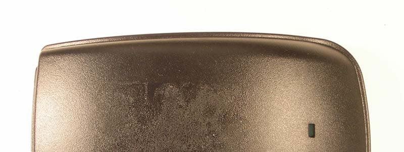
Click to zoom
Application Details
- Equipment Class
- DSC - Part 15 Security/Remote Control Transmitter
- Date of Grant
- Jul 06, 2005
- Application Purpose
- Original Equipment
- Date of Application
- Jul 06, 2005
- Equipment Note
- Locator Hub
- Frequency Range
- 433.92000000 - 433.92000000
- Company
- Nielsen Audio Inc
- Country
- United States
Documents & Files
Document Text
Text extracted from the exhibit documents filed with the FCC. Open a document above to read the original.
Users Manual
A Complete Guide to Participating in the Arbitron Ratings How to Use Yo u r P e r s o n a l Meter Your Representative: Page 1 Welcome! Page 2 How does it work? • Your Personal Meter • Your Recharger • The Household Collector Page 4 How to keep your Meter with you Page 6 When do you recharge your Personal Meter? Page 7 What do the messages mean? Page 8 How to earn points toward cash gifts and bonuses Contents Page 10 What about traveling? Page 10 Need to reach us? Page 11 Quick troubleshooting guide Page 12 Common questions and answers Page 14 An important message to parents of school-age children Inside back cover Important safety instructions Back cover FCC notice Welcome to the Arbitron TV and Radio Ratings! Your part in these ratings is very important! We are counting on you and everyone in your household age 6 and older to tell us what you watch on television and what you listen to on the radio. With your information, TV and radio stations and others in the TV and radio industries can learn more about the programs that are watched or listened to. All you have to do is wear your Personal Meter every day from the time you rise until you retire for the day. Right before you go to bed, remember to put your Personal Meter in its Recharger. That’s all there is to it! We want to make sure all your listening and viewing is included in the ratings— no matter how much or how little you watch TV or listen to the radio. As our way of thanking you, there is a point system with rewards for wearing your Personal Meter, so the more you wear your Personal Meter, the more you can earn as a reward. This booklet explains the bonuses and the messages you will see on the Personal Meter’s Recharger. It also describes the equipment in your home and tells you what to do in case you have a problem or a question. Remember, just as you are helping us, we are here to help you. If you ever need to contact us for any reason, please call your Arbitron Ratings representative listed on the cover of this book. We think you will enjoy being a part of this ratings panel, and we thank you for joining. Sincerely, Steve Morris President, Arbitron Radio Ratings Welcome! 1 Your Personal Meter picks up TV and radio station codes wherever you go. 2 How does it work? Your Personal Meter Your Personal Meter is just for you. Your name will appear when you put your Personal Meter into its Recharger. Please make sure you are the only one using your Personal Meter. Your Personal Meter picks up what you watch on TV and listen to on the radio. It automatically identifies the radio station or TV program by picking up special “encoded” signals sent by TV and radio stations. It can also pick up encoded signals that are played over the Internet or at places such as stores, amusement parks, and movie theaters that participate with us in this research. These signals are silent to the human ear. However, if you can hear sound from your TV or radio or other encoded source, the Personal Meter will pick up the signal. Your Personal Meter doesn’t “hear” or record your conversations or any other sounds. Your Personal Meter has a green light on the side to show you the Meter is working. The green light is attached to a special sensor that knows if you are carrying the Meter with you. All you have to do is wear your Personal Meter to keep the green light on. You simply wear your Personal Meter and it receives station signals wherever you are. It’s important that you always wear your Personal Meter so it will report all your TV viewing and radio listening. We ask that you wear it from the time you first wake up and during all your daily activities—at home, in the car, or at work. 3 Your Recharger Your Recharger collects your TV viewing and radio listening information as well as recharges the Personal Meter battery. At the end of each day, you place the Personal Meter into the Recharger so all your TV viewing and radio listening for that day will be included. To make it easy, we ask you to place the Recharger in your bedroom where you can easily see it when you first wake up. The Recharger also displays special messages to you whenever you place the Personal Meter back into the unit. It will tell you how many points you have earned for wearing your Meter for the current and previous days. It will also tell you what your point total is for the current week and what it was for the previous week. There are two buttons located near the display on the front of your Recharger. They are used only for testing by our technicians and will do nothing when pushed. The Household Collector The Collector is plugged into an electrical outlet and into your telephone line. It collects viewing and listening data from each Recharger by communicating with these units through the electrical wiring in your home. It also transmits a silent signal that can be detected by your Personal Meter when it is within your house. This allows us to separate your media use at home from your media use in other places. The Collector then sends your household’s information to our main computer once each day by making a very short call, lasting just a couple minutes very early in the morning, usually between 4A M and 6A M. We can then combine your information with information from other households in your area to produce the TV and radio ratings. This call will not affect your phone service. You can use the telephone whenever you want. There is no additional cost to your phone bill. When connected properly, your Collector will show a solid green light on the front. If the green light is flashing or out, please refer to the troubleshooting section of this guide for instructions. Occasionally an orange light may come on and flash. This is normal. 4 How to keep your Meter with you Three simple rules 1. Remove your Personal Meter from its Recharger as soon as you wake up. 2. Wear your Personal Meter wherever you go and make sure its green light stays on. 3. At the end of the day, just before yo…
Text truncated - open the document above for the full version.
Block Diagram
Model HP106A Locator Hub In Home / Out of Home Transmitter Description Page 1 of 6 Arbitron Proprietary Information ©2005 Arbitron Inc 1 MODEL HP106A LOCATOR HUB IN HOME / OUT OF HOME TRANSMITTER DESCRIPTION A.1 PPM IN HOME/OUT OF HOME INDICATOR OVERVIEW Subscribers to Arbitron’s ratings service are not just interested in which radio or television station a panelist listens to, but also where the station was heard: In their home, or somewhere out of home such as in their car, at work, etc? To meet this need, the PPM system’s HP106A Locator Hub (denoted the PL3150 Locator Hub and also known as the household collector) contains a low power 433 MHz RF transmitter that acts as a continuous “at-home” beacon. If a panelist is at home and within 100 feet of the Hub transmitter, an RF receiver in his personal meter (i.e., his PPM) will detect the transmission and log a positive “in Home” event. The PPM records successful detections in its listening log every few minutes. The In Home/Out of Home Indicator system is illustrated in Figure A-1 below. Figure A-1: In Home/Out of Home Indicator system A.2 IN HOME/OUT OF HOME TRANSMITTER The HP106A Locator Hub uses a Linx TXM-433-LC, a 433.92 MHz low-power RF transmitter, mated to a custom antenna to provide an “at home” signal to panelist PPM Hub (Collector) Open Air Range Model HP106A Locator Hub In Home / Out of Home Transmitter Description Page 2 of 6 Arbitron Proprietary Information ©2005 Arbitron Inc 2 meters. The TXM-433-LC is driven by the Echelon Neuron microcontroller. As built, with the output power control resistor (R35 = 1.1K Ohms) and VCC = 5V, the nominal power output = -2 dBm for FCC 15.231 compliance. Emissions testing at an independent lab determined that R35=1.1K Ohms (with a 14% duty cycle) permits the maximum transmitted power under FCC rules. See Figures A-2 through A-5. Figure A-2: Linx TXM-433-LC Transmitter Figure A-3: In Home / Out of Home System Block Diagram 433.92 MHz Module Linx TXM-433-LC 433.92 MHz Module Linx TXM-433-LC ACAC Neuron Microcontroller Neuron Microcontroller Antenna Arbitron Custom 1010 0841 Antenna Arbitron Custom 1010 0841 AC Power Line Communication Interface AC Power Line Communication Interface Power SupplyPower Supply R35 (LADJ Resistor) 1.1K Ohm Nominal R22 0 Ohm VCC = 5V Model HP106A Locator Hub In Home / Out of Home Transmitter Description Page 3 of 6 Arbitron Proprietary Information ©2005 Arbitron Inc 3 Figure A-4: Linx TXM-433-LC Transmitter Power Output Versus R35 Value (Use 5V line.) Figure A-5: HP106A PCB Topside Component Layout R35 Model HP106A Locator Hub In Home / Out of Home Transmitter Description Page 4 of 6 Arbitron Proprietary Information ©2005 Arbitron Inc 4 A.3 FCC TRANSMITTER REGULATIONS As an intentional radiator, the In Home/Out of Home transmitter needs to be compliant with FCC regulations outlined under section 15.231, which contains five subsections: (a), (b), (c), (d), and (e). Subsection (a) allows for three types of intentional transmitters: manually operated, or automatically triggered but restricted to transmitting less than 2 seconds per hour. Subsection (b) specifies the power limits for subsection (a) devices, while subsections (c) and (d) specify bandwidth and band-limit requirements. Subsection (e) provides a special exception to subsection (a) with allowable transmission levels of less than half those provided under subsection (b). In addition, subsection (e) devices must not transmit for greater than one second and the silent period between transmissions must be at least 30 times the duration of the transmission but in no case less than 10 seconds. Lastly, subsection (e) devices must meet the bandwidth and band-limit requirements of subsection (b), which includes a power-measuring requirement covered under section 15.35. Specifically, the measured field strength must be determined from the average absolute voltage during a 0.1 second interval when the transmitted pulse code is at its maximum. For reference, the Subsection (e) 433.92 MHz power limit is 4,399 μV/m (72.9 dBμV/m). 1. Transmitter Power The Linx TXM433 module transmits at a nominal -2dBm power level. 2. Transmitter 100 ms burst duty cycle The transmitter emits 2 ms power pulses every 16 ms. Within a worst-case 100 ms window there are 7 power pulses, resulting in 2x7/100 = 14% duty cycle. [Note: 15.35(b) ...When average radiated emission measurements are specified in the regulations there is also a limit on the radio frequency emissions corresponding to 20 dB above the maximum permitted average limit for the frequency being investigated .... So, since 20*log(0.1) = -20dB, this means that a duty cycle less than 10% is not useful for lowering the FCC power level compliance further.] 3. Total Transmission Time The total transmission time is 978 ms. Note this is less than the one second section 15.231(e) maximum. 4. Transmitter Silent Period The transmitter will be silent for 30.022 seconds between transmissions. Section 15.231 (e) requires a minimum silent period of 30*0.978 =29.340 seconds or 10.00 seconds, which ever is greater. Model HP106A Locator Hub In Home / Out of Home Transmitter Description Page 5 of 6 Arbitron Proprietary Information ©2005 Arbitron Inc 5 5. Transmitter Transmission Period The transmitter 0.978 second ‘on’ period followed by the 30.022 second ‘off’ period equates to a 31.000 second period repeating transmission pattern. The resulting transmitted pattern is illustrated in Figures A-6 and A-7 below. Figure A-6: In Home/Out of Home Transmitter Quiescent Period Model HP106A Locator Hub In Home / Out of Home Transmitter Description Page 6 of 6 Arbitron Proprietary Information ©2005 Arbitron Inc 6 Figure A-7: Transmitter Duty Cycle
External Photos
FCC ID: IGKHP106A WO: EF0178 IC: 4213-HP106A Company: Arbitron Top Bottom FCC ID: IGKHP106A WO: EF0178 IC: 4213-HP106A Company: Arbitron Left side Right side FCC ID: IGKHP106A WO: EF0178 IC: 4213-HP106A Company: Arbitron Front side Back side
ID Label/Location Info
The following photo indicates the placement of label on the device. The actual FCC ID is shown in label exhibit.
Internal Photos
FCC ID: IGKHP106A WO: EF0178 IC: 4213-HP106A Company: Arbitron Top side of printed circuit board Bottom side of printed circuit board FCC ID: IGKHP106A WO: EF0178 IC: 4213-HP106A Company: Arbitron Left side of printed circuit board
Operational Description
Model HP106A Locator Hub In Home / Out of Home Transmitter Description Page 1 of 6 Arbitron Proprietary Information ©2005 Arbitron Inc 1 MODEL HP106A LOCATOR HUB IN HOME / OUT OF HOME TRANSMITTER DESCRIPTION A.1 PPM IN HOME/OUT OF HOME INDICATOR OVERVIEW Subscribers to Arbitron’s ratings service are not just interested in which radio or television station a panelist listens to, but also where the station was heard: In their home, or somewhere out of home such as in their car, at work, etc? To meet this need, the PPM system’s HP106A Locator Hub (denoted the PL3150 Locator Hub and also known as the household collector) contains a low power 433 MHz RF transmitter that acts as a continuous “at-home” beacon. If a panelist is at home and within 100 feet of the Hub transmitter, an RF receiver in his personal meter (i.e., his PPM) will detect the transmission and log a positive “in Home” event. The PPM records successful detections in its listening log every few minutes. The In Home/Out of Home Indicator system is illustrated in Figure A-1 below. Figure A-1: In Home/Out of Home Indicator system A.2 IN HOME/OUT OF HOME TRANSMITTER The HP106A Locator Hub uses a Linx TXM-433-LC, a 433.92 MHz low-power RF transmitter, mated to a custom antenna to provide an “at home” signal to panelist PPM Hub (Collector) Open Air Range Model HP106A Locator Hub In Home / Out of Home Transmitter Description Page 2 of 6 Arbitron Proprietary Information ©2005 Arbitron Inc 2 meters. The TXM-433-LC is driven by the Echelon Neuron microcontroller. As built, with the output power control resistor (R35 = 1.1K Ohms) and VCC = 5V, the nominal power output = -2 dBm for FCC 15.231 compliance. Emissions testing at an independent lab determined that R35=1.1K Ohms (with a 14% duty cycle) permits the maximum transmitted power under FCC rules. See Figures A-2 through A-5. Figure A-2: Linx TXM-433-LC Transmitter Figure A-3: In Home / Out of Home System Block Diagram 433.92 MHz Module Linx TXM-433-LC 433.92 MHz Module Linx TXM-433-LC ACAC Neuron Microcontroller Neuron Microcontroller Antenna Arbitron Custom 1010 0841 Antenna Arbitron Custom 1010 0841 AC Power Line Communication Interface AC Power Line Communication Interface Power SupplyPower Supply R35 (LADJ Resistor) 1.1K Ohm Nominal R22 0 Ohm VCC = 5V Model HP106A Locator Hub In Home / Out of Home Transmitter Description Page 3 of 6 Arbitron Proprietary Information ©2005 Arbitron Inc 3 Figure A-4: Linx TXM-433-LC Transmitter Power Output Versus R35 Value (Use 5V line.) Figure A-5: HP106A PCB Topside Component Layout R35 Model HP106A Locator Hub In Home / Out of Home Transmitter Description Page 4 of 6 Arbitron Proprietary Information ©2005 Arbitron Inc 4 A.3 FCC TRANSMITTER REGULATIONS As an intentional radiator, the In Home/Out of Home transmitter needs to be compliant with FCC regulations outlined under section 15.231, which contains five subsections: (a), (b), (c), (d), and (e). Subsection (a) allows for three types of intentional transmitters: manually operated, or automatically triggered but restricted to transmitting less than 2 seconds per hour. Subsection (b) specifies the power limits for subsection (a) devices, while subsections (c) and (d) specify bandwidth and band-limit requirements. Subsection (e) provides a special exception to subsection (a) with allowable transmission levels of less than half those provided under subsection (b). In addition, subsection (e) devices must not transmit for greater than one second and the silent period between transmissions must be at least 30 times the duration of the transmission but in no case less than 10 seconds. Lastly, subsection (e) devices must meet the bandwidth and band-limit requirements of subsection (b), which includes a power-measuring requirement covered under section 15.35. Specifically, the measured field strength must be determined from the average absolute voltage during a 0.1 second interval when the transmitted pulse code is at its maximum. For reference, the Subsection (e) 433.92 MHz power limit is 4,399 μV/m (72.9 dBμV/m). 1. Transmitter Power The Linx TXM433 module transmits at a nominal -2dBm power level. 2. Transmitter 100 ms burst duty cycle The transmitter emits 2 ms power pulses every 16 ms. Within a worst-case 100 ms window there are 7 power pulses, resulting in 2x7/100 = 14% duty cycle. [Note: 15.35(b) ...When average radiated emission measurements are specified in the regulations there is also a limit on the radio frequency emissions corresponding to 20 dB above the maximum permitted average limit for the frequency being investigated .... So, since 20*log(0.1) = -20dB, this means that a duty cycle less than 10% is not useful for lowering the FCC power level compliance further.] 3. Total Transmission Time The total transmission time is 978 ms. Note this is less than the one second section 15.231(e) maximum. 4. Transmitter Silent Period The transmitter will be silent for 30.022 seconds between transmissions. Section 15.231 (e) requires a minimum silent period of 30*0.978 =29.340 seconds or 10.00 seconds, which ever is greater. Model HP106A Locator Hub In Home / Out of Home Transmitter Description Page 5 of 6 Arbitron Proprietary Information ©2005 Arbitron Inc 5 5. Transmitter Transmission Period The transmitter 0.978 second ‘on’ period followed by the 30.022 second ‘off’ period equates to a 31.000 second period repeating transmission pattern. The resulting transmitted pattern is illustrated in Figures A-6 and A-7 below. Figure A-6: In Home/Out of Home Transmitter Quiescent Period Model HP106A Locator Hub In Home / Out of Home Transmitter Description Page 6 of 6 Arbitron Proprietary Information ©2005 Arbitron Inc 6 Figure A-7: Transmitter Duty Cycle
Operational Description
TOP VIEW .360 .500 PINOUTS LC-SERIES TRANSMITTER MODULE DATA GUIDE ■Remote control ■Keyless entry ■Garage / Gate openers ■Lighting control ■Medical monitoring / Call systems ■Remote industrial monitoring ■Periodic data transfer ■Home / Industrial automation ■Fire / Security alarms ■Remote status / Position sensing ■Long-range RFID ■ Wire Elimination APPLICATIONS INCLUDE: ■Low Cost ■No External RF Components Required ■Ultra-low Power Consumption ■Compact Surface-Mount Package ■Stable SAW-based Architecture ■Supports Data Rates to 5,000 bps ■Wide Supply Range (2.7-5.2 VDC) ■Direct Serial Interface ■Low Harmonics ■No Production Tuning The LC Series is ideally suited for volume use in OEM applications such as remote control, security, identification, and periodic data transfer. Packaged in a compact SMD package, the LC transmitter utilizes a highly optimized SAW architecture to achieve an unmatched blend of performance, size, efficiency and cost. When paired with a matching LC-Series receiver, a highly reliable wireless link is formed, capable of transferring serial data at distances in excess of 300 feet. No external RF components, except an antenna, are required, making design integration straightforward, even for engineers lacking previous RF experience. TXM-315-LC TXM-418-LC TXM-433-LC PHYSICAL DIMENSIONS DESCRIPTION: FEATURES: Revised 10/3/2 PART# DESCRIPTION EVAL-***-LCBasic Evaluation Kit MDEV-***-LCMaster Development Kit TXM-315-LC Transmitter 315 MHZ TXM-418-LCTransmitter 418 MHZ TXM-433-LCTransmitter 433 MHZ RXM-315-LCReceiver 315 MHZ RXM-418-LCReceiver 418 MHZ RXM-433-LCReceiver 433 MHZ *** Insert Frequency Not covered in this manual LC Transmitters are supplied in tube packaging - 50 pcs. per tube. ORDERING INFORMATION PERFORMANCE DATA– TXM-***-LC Page 2 Parameter LCTX 418MHzDesignationMin.TypicalMax.UnitsNotes Frequency of CarrierF C 417.925418418.075MHz– Harmonic EmissionsP H ––-40dBc4 Parameter LCTX 315MHzDesignationMin.TypicalMax.UnitsNotes Frequency of CarrierF C 314.925315.0315.075MHz– Harmonic EmissionsP H ––-40dBc4 Parameter LCTX 433MHzDesignationMin.TypicalMax.UnitsNotes Frequency of CarrierF C 433.845433.92433.995MHz– Harmonic EmissionsP H ––-45dBc4 figure 1: Test/Basic application circuit ABOUT THESE MEASUREMENTS The performance parameters listed below are based on module operation at 25°C from a 3.3VDC supply unless otherwise noted. Figure 1 at the right illustrates the connections necessary for testing and operation. It is recommended that all ground pins be connected to the groundplane. 1. Current draw with data pin held continuously high. 2. Current draw with 50% mark/space ratio. 3. Current draw with data pin low. 4. RF out connected to 50Ωload. 5, Ladj (pin 4) through 430Ωresistor. Notes: Parameters LCTX 433, 418, 315MHzDesignationMin.TypicalMax.UnitsNotes Operating Voltage Range V CC 2.7–5.2Volts– Current ContinuousI CC –3.06.0mA1, 5 Current AverageI CA –1.5–mA2, 5 Current In SleepI SLP ––1.5μA3 Data Input LowV IL 0–0.4Volts– Data Input HighV IH 2.5–V CC Volts– Oscillator Start-up TimeT OSU –– 80μS4 Oscillator Ring-down TimeT ORD ––100nSec4 Output PowerP O -40+4dBm4 Page 3 Absolute Maximum Ratings: Supply voltage V CC , using pin 7-0.3to+6 VDC Operating temperature-30°Cto+70°C Storage temperature-45°Cto+85°C Soldering temperature+225°C for 10 sec. Any input or output pin-0.3toV CC *NOTE* Exceeding any of the limits of this section may lead to permanent damage of the device. Furthermore, extended operation at these maximum ratings may reduce the life of this device. 0 -1 -4 -5 -6 -7 2.5 3.0 3.5 4.04.5 -2 -3 SUPPLY VOLTAGE +1 +3 +2 +4 +5 +6 +7 +8 5.0 (V) 2.5 3.0 3.5 4.04.5 5.0 (V)(V) SUPPLY VOLTAGESUPPLY VOLTAGE 1 3 2 4 5 6 7 8 9 10 11 12 0 With 430Ω resistor at Iadj (pin) With Iadj tied to ground Supply Current (mA) 0 -1 -4 -5 -6 -7 2.5 3.0 3.5 4.04.5 -2 -3 SUPPLY VOLTAGESUPPLY VOLTAGE +1 +3 +2 +4 +5 +6 +7 +8 5.0 (V)(V) 2.5 3.0 3.5 4.04.5 5.0 (V) SUPPLY VOLTAGE 1 3 2 4 5 6 7 8 9 10 11 12 0 dBm With 430Ω resistor at Iadj (pin) With Iadj tied to ground pg Output Power figure 4: Typical Oscillator Turn-On Time figure 2: Consumption vs. Supply Voltage TYPICAL PERFORMANCE GRAPHS figure 5: Typical Oscillator Turn-Off Time figure 3: Typical RF power into 50Ω Data Carrier Data Carrier Page 4 TRANSMITTER AUTOMATED ASSEMBLY For high-volume assembly most users will want to auto-place the modules. The modules have been designed to maintain compatibility with most pick-and-place equipment; however, due to the module's hybrid nature certain aspects of the automated assembly process are far more critical than for other component types. Following are brief discussions of the three primary areas where caution must be observed. Reflow Temperature Profile The single most critical stage in the automated assembly process is the reflow process. The reflow profile below should be closely followed since excessive temperatures or transport times during reflow will irreparably damage the modules. Assembly personnel will need to pay careful attention to the oven's profile to insure that it meets the requirements necessary to successfully reflow all components while still meeting the limits mandated by the modules themselves. Shock During Reflow Transport Since some internal module components may reflow along with the components placed on the board being assembled, it is imperative that the module not be subjected to shock or vibration during the time solder is liquidus. Washability The modules are wash resistant, but are not hermetically sealed. They may be subject to a standard wash cycle; however, a twenty-four-hour drying time should be allowed before applying electrical power to the modules. This will allow any moisture that has migrated into the module to evaporate, thus eliminating the potential for shorting during power-up or testing. 125∞C 600 0 50 100 150 200 250 300 ∞C 120180240300 3090150210270330360 180∞C 210∞C 220∞C Temperature Time (Seconds) Ideal Curve Limit Curve Forced Air…
Text truncated - open the document above for the full version.
Test Report
REPORT: EF0178-1 FCC ID: IGKHP106A IC: 4213A-HP106A _____________________________________________________________ Test Report Report No EF0178-1 Client Arbitron Phone 410-312-8523 Fax none FRN 007870256 Models Model HP106A Locator Hub FCC ID IGKHP106A IC # 4231A-HP106A Equipment Type Low Power Periodic Communications Device Transmitter Equipment Code DXX Results As detailed within this report Prepared by Josh LeBlanc – Test Engineer Authorized by Michael Buchholz – EMC Manager Issue Date 6/14/05 Conditions of issue This Test Report is issued subject to the conditions stated in ‘terms and conditions’ section of this LLC • 527 Great Road • Littleton, MA • TEL (978) 486-8880 • FAX (978) 486-8828 Page 1 of 17 Curtis-Straus REPORT: EF0178-1 FCC ID: IGKHP106A IC: 4213A-HP106A _____________________________________________________________ Summary...........................................................................................................3 Product Description (Transmitter)..................................................................3 Test Methodology..............................................................................................3 Statement of Conformity....................................................................................4 EUT Configuration.............................................................................................5 Spurious Radiated Emissions............................................................................6 Emission Bandwidth..........................................................................................8 Fundamental Field Strength and Duty Cycle.....................................................9 AC Line Conducted Emission Measurements.................................................11 Voltage Variations...........................................................................................11 Test Equipment Used......................................................................................12 Terms And Conditions.....................................................................................13 A2LA Accreditation..........................................................................................15 LLC • 527 Great Road • Littleton, MA • TEL (978) 486-8880 • FAX (978) 486-8828 Page 2 of 17 Curtis-Straus REPORT: EF0178-1 FCC ID: IGKHP106A IC: 4213A-HP106A _____________________________________________________________ Summary This report is an application for certification of a transmitter operating pursuant to 47 CFR 15.231 and RSS-210 6.1. The product covered by this report is the Model HP106A Locator Hub. It has only a transmitter which operates at 433.98MHz. Product Description (Transmitter) MN: Model HP106A Locator Hub SN: Test sample 1 Cables: two RJ11 pots, Power Source: 120V AC Operating Mode: Constant periodic Tx mode Test Methodology Radiated emissions testing was performed according to the procedures specified in ANSI C63.4 (2003). The EUT was maximized around one axis, as the EUT can only be installed in one position. The EUT has an integrated internal antenna which can not be maximized separately. The standard test voltage was 120VAC. The ambient environmental conditions were as follows: Date Temperature Humidity 2/28/05 25.7°C 9% 3/3/05 25.1°C 10% 3/23/05 25.6°C 12% 3/25/05 25.3°C 18% 3/29/05 24.7°C 24% 3/30/05 26.9°C 22% 4/27/05 24.7°C 30% 5/20/05 25.3°C 26% Frequency range investigated: 30 MHz- 4.34 GHz Measurement Distance: Frequency (MHz) Distance (m) Comments AC conducted 0.15 – 30MHz - Conducted Fundamental 433.92MHz 3 m Radiated Spurious & harmonics 30 – 4340 MHz 3 m Radiated All readings are peak unless otherwise noted. LLC • 527 Great Road • Littleton, MA • TEL (978) 486-8880 • FAX (978) 486-8828 Page 3 of 17 Curtis-Straus REPORT: EF0178-1 FCC ID: IGKHP106A IC: 4213A-HP106A _____________________________________________________________ Statement of Conformity The HP106A has been found to conform with the following parts of the 47 CFR as detailed below: RSS-210 47 CFR Part # Comments 5.7 15.15(b) The product contains no user accessible controls that increase transmission power above allowable levels. 5.10 15.19 The label is shown in the label exhibit. 5.11 15.21 Information to the user is shown in the instruction manual exhibit. 15.27 No special accessories are required for compliance. 15.31(e) The voltage was varied to ±15% of the rated voltage. The fundamental did not change. 5.5 15.203 The device utilizes an integrated antenna. 15.204 The antenna is not accessible to the user and therefore cannot be easily removed. 6.1.1 (e) 15.205 15.209 The fundamental is not in a restricted band and the spurious emissions in the restricted bands comply with the general emission limits of 15.209. 6.6, 9 15.207 AC line conducted emissions. 6.1.1 (a) (1) 15.231(a) (1) Product complies with 15.231(e). (2) (2) Product complies with 15.231(e). (3) (3) Product complies with 15.231(e). (4) (4) Product complies with 15.231(e). 6.1.1 (b) 15.231(b) Product complies with 15.231(e). 6.1.1 (c) 15.231(c) 20dB bandwidth of the emission is less than 0.25% of the center frequency. 6.1.1 (d) 15.231(d) Frequency tolerance is not required, because product does not operate in the specified band. 6.1.1 (e) 15.231(e) Fundamental and spurious emissions meet the limits specified in this section. Modifications required for compliance: In order to meet the fundamental emission limit, R35 was increased to 1.1kOhms. LLC • 527 Great Road • Littleton, MA • TEL (978) 486-8880 • FAX (978) 486-8828 Page 4 of 17 Curtis-Straus REPORT: EF0178-1 FCC ID: IGKHP106A IC: 4213A-HP106A _____________________________________________________________ EUT Configuration EUT Configuration Work Order: F0178 Company: Arbitron Company Address: 9705 Patuxent Wood Drive Columbia, MD 21046 Contact: Robert Shelley MNSN EUT: HP106ATest Sample 1 EUT Description: Model HP106A Locator Hub E…
Text truncated - open the document above for the full version.
Contact Information
Applicant
Jack Charles Crystal(Principal Architect)
Test Firm
BUREAU VERITAS CONSUMER PRODUCTS SERVICES, INC.Ozgur Ozturk
[email protected]978-486-8880
Technical Specifications
| # | Rule Parts | Frequency Range | Power Output |
|---|---|---|---|
| 1 | 15.231(e) | 433.92 MHz - 433.92 MHz | - |
Other Applications from Nielsen Audio Inc
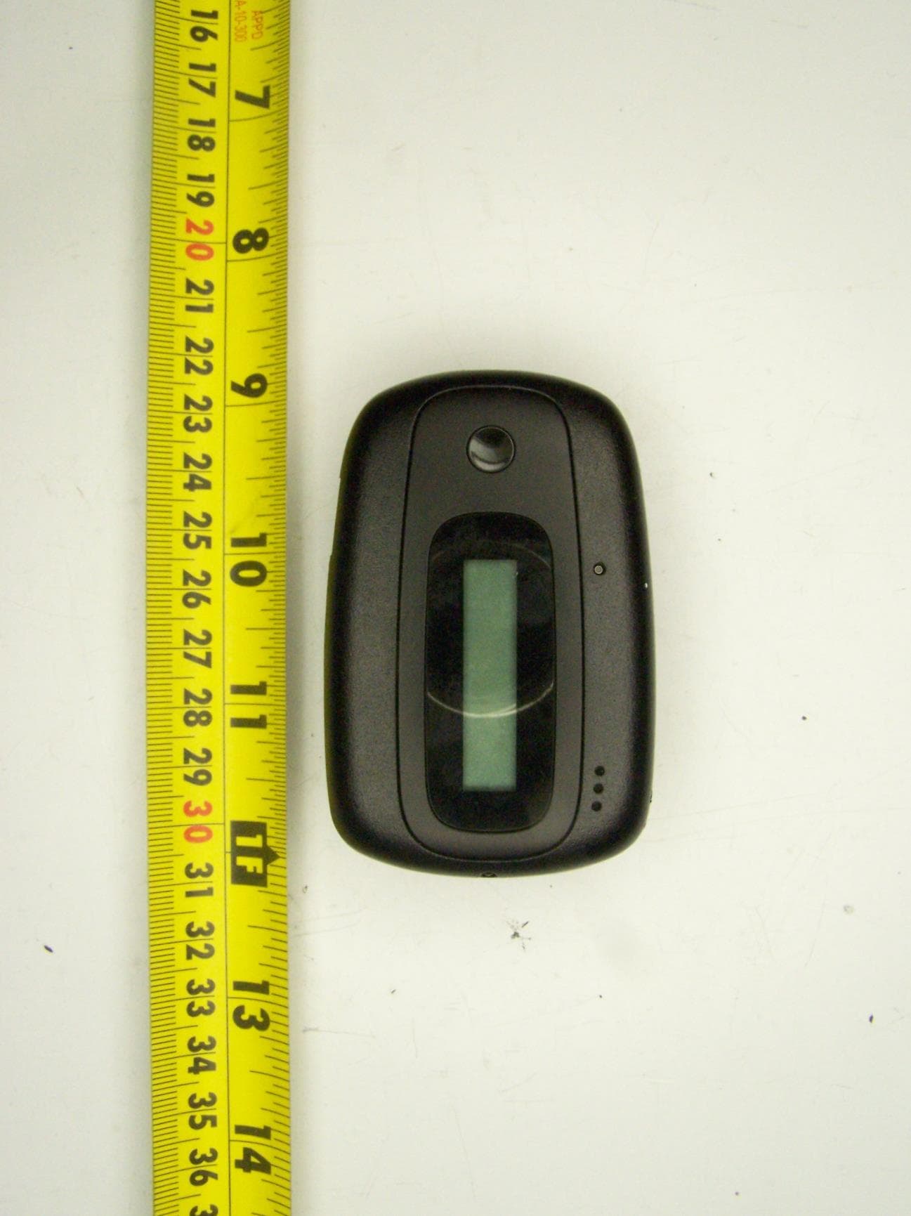
IGKDA120
Aug 13, 2014PPM 360 Meter
Equipment Class
PCT - PCS Licensed Transmitter worn on body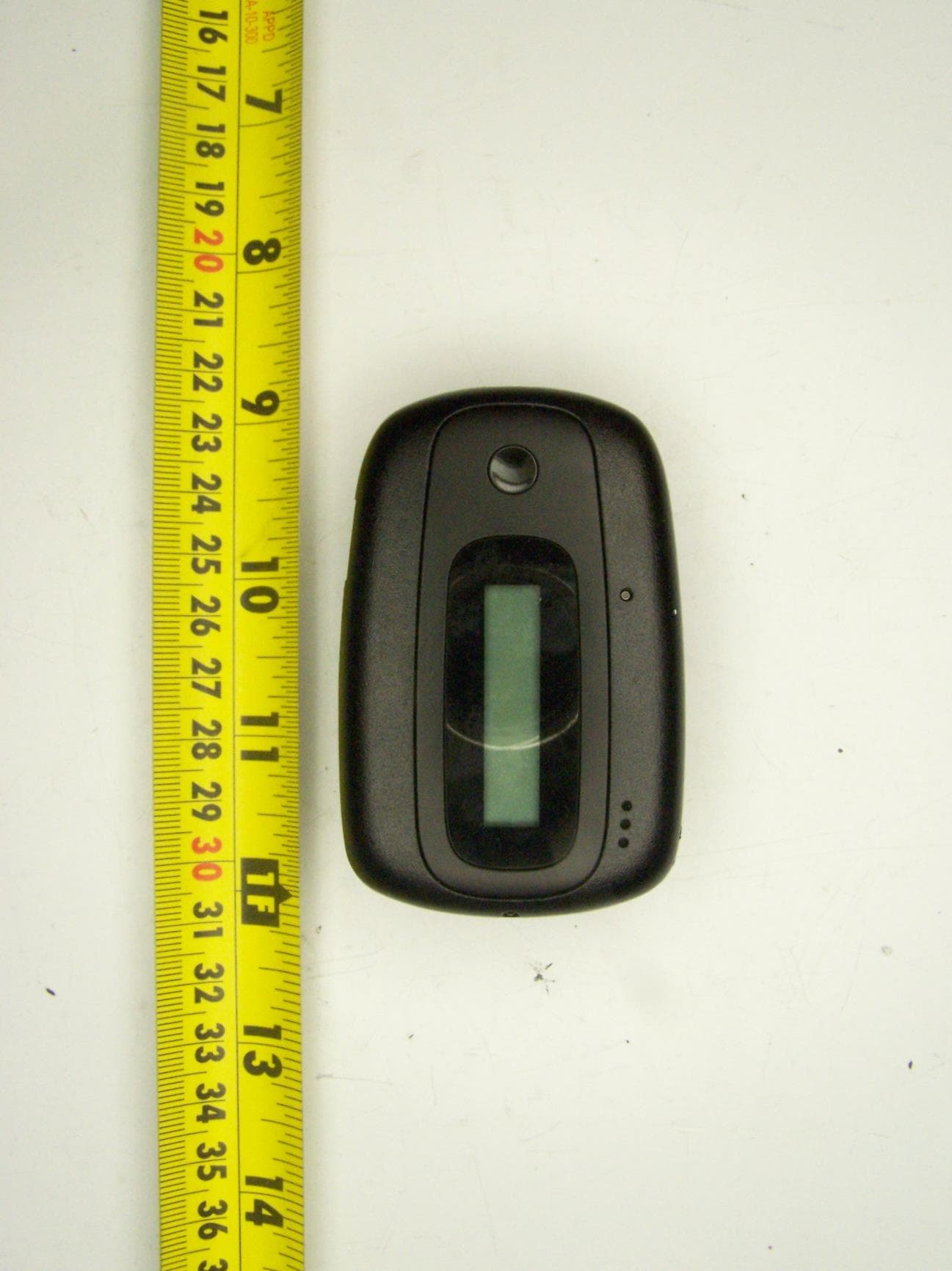
IGKDA118
Aug 13, 2014PPM 360 Meter
Equipment Class
DSS - Part 15 Spread Spectrum Transmitter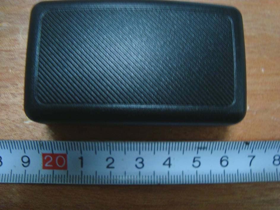
IGKDA114A
Apr 08, 2010Gen2 Beacon
Equipment Class
DSS - Part 15 Spread Spectrum Transmitter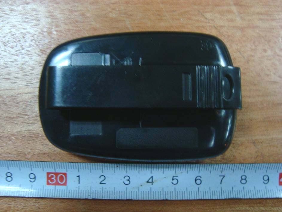
IGKDA113A
Feb 15, 2010Gen2 Meter
Equipment Class
DSS - Part 15 Spread Spectrum Transmitter
IGKXT101A
Apr 11, 2007In-Car Beacon
Equipment Class
DSC - Part 15 Security/Remote Control Transmitter