IIO-0236WLPC11Mbps Wireless LAN PCMCIA Adapter
CNet Technology Inc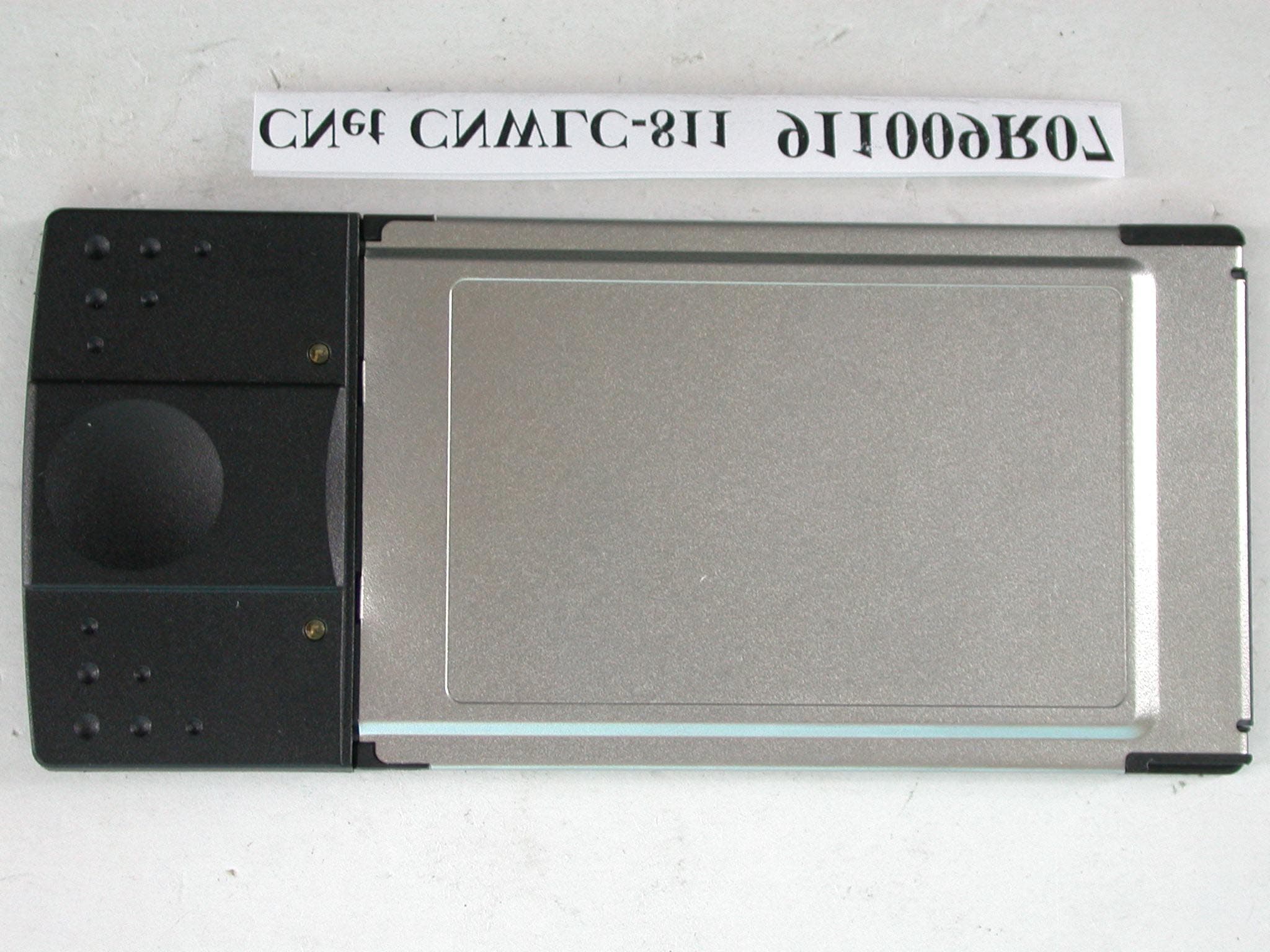
Click to zoom
Application Details
- Equipment Class
- DTS - Digital Transmission System
- Date of Grant
- Dec 05, 2002
- Application Purpose
- Original Equipment
- Date of Application
- Dec 05, 2002
- Equipment Note
- 11Mbps Wireless LAN PCMCIA Adapter
- Frequency Range
- 2412.00000000 - 2462.00000000
- Company
- CNet Technology Inc
- Country
- Taiwan
Documents & Files
Document Text
Text extracted from the exhibit documents filed with the FCC. Open a document above to read the original.
Users Manual
11Mbps Wireless LAN PC Card User’s Guide Version 1.3 INFORMATION TO USER Federal Communications Commission Statement This equipment has been tested and found to comply with the limits for a Class B digital device, pursuant to Part 15 of the FCC Rules. These limits are designed to provide reasonable protection against harmful interference in a residential installation. This equipment generates, uses and can radiate radio frequency energy and, if not installed and used in accordance with the instructions, may cause harmful interference to radio communications. However, there is no guarantee that interference will not occur in a particular installation. If this equipment does cause harmful interference to radio or television reception, which can be determined by turning the equipment off and on, the user is encouraged to try to correct the interference by one of the following measures: Reorient or relocate the receiving antenna. Increase the separation between the equipment or device. Connect the equipment to an outlet other than receiver’s. Consult a dealer or an experienced radio/TV technician for assistance FCC Caution: To assure continued compliance, (example - use only shielded interface cables when connecting to computer or peripheral devices) any changes or modifications not expressly approved by the party responsible for compliance could void the user’s authority to operate this equipment. This device complies with Part 15 of the FCC Rules. Operation is subject to the following two conditions: (1) This device may not cause harmful interference, and (2) this device must accept any interference received, including interference that may cause undesired operation. IMPORTANT NOTE: FCC Radiation Exposure Statement: This equipment complies with FCC radiation exposure limits set forth for an uncontrolled environment. End-users must follow the specific operating instructions for satisfying RF exposure compliance. This transmitter must not be co-located or operating in conjunction with any other antenna or transmitter. Regulatory The wireless LAN PC Card must be installed and used in strict accordance with the manufacturer’s instructions. This device complies with the following radio frequency and safety standards. Europe - R&TTE Directive This device complies with the specifications listed below: ⌧ ETS 300-826 General EMC requirements for Radio equipment. ⌧ ETS 300-328 Technical requirements for Radio equipment. ⌧ EN60950 Safety requirements for Radio equipment. EU Countries not intended for use The ETSI version of this device is intended for home and office use in Austria, Belgium, Denmark, Finland, France (with Frequency channel restrictions). Germany, Greece, Ireland, Italy, Luxembourg, Netherlands, Portugal, Spain, Sweden and United Kingdom. The ETSI version of this device is also authorized for use in EFTA member states Iceland, Liechtenstein, Norway and Switzerland. 1 Table of Contents Chapter 1: Introduction.............................................................................................3 The 11Mbps Wireless LAN PC Card...................................................................3 Features..............................................................................................................3 Package Contents...............................................................................................4 System Requirements.........................................................................................4 Chapter 2: Network Configuration and Planning......................................................5 Wireless LAN Basic.............................................................................................5 Network Topology................................................................................................5 Roaming..............................................................................................................7 Chapter 3: Installing the Drivers and Configuration Utility for Windows 9X/ME/ 2000..............................................................................................................8 Running the Auto Driver & Utility Installation.......................................................8 Inserting the adapter..........................................................................................10 Chapter 4: Configuration Utility...............................................................................12 Using the configuration utility.............................................................................12 Chapter 5: Installation Procedure Under Windows NT 4.0.....................................19 About Windows NT 4.0......................................................................................19 Installing the Driver............................................................................................19 Configuration / Uninstall....................................................................................22 Chapter 6: Installation Procedure Under WindowsXP............................................23 About Windows XP............................................................................................23 Installing the Driver / Utility................................................................................23 Configuration Under WinXP...............................................................................23 Uninstall Procedure Under WinXP.....................................................................24 Appendix A: Troubleshooting..................................................................................25 Appendix B: Glossary.............................................................................................26 Appendix C: Specifications.....................................................................................28 2 Chapter 1: Introduction The 11Mbps Wireless LAN PC Card The 11Mbps Wireless LAN PC Card now has a ne…
Text truncated - open the document above for the full version.
Users Manual
Encryption On the Encryption screen, show in Fig 4-5, you can set the level of security with which you will be using the WLAN PC Card. Under the drop-down box, you can choose to have WEP encryption Disabled, 64-Bit, or 128- Bit Wired Equivalent Privacy (WEP) is an encryption scheme use to protect wireless data communi- cation. If you decide to use encryption, you can choose any of the available WEP keys (1 to 4). You also have option to select the WEP mode (Mandatory/optional). If you select “Mandatory”, then not only WEP will be used, but also any other station needs to use WEP encryption in order to establish a communication with your station. This requirement is in line with the IEEE 802.11b standard. If, on the other hand, you choose “Option”, then your station can communication with every other station regardless if they use WEP or not. The Disabled setting prevents the sharing of data with other computers on the WEP network. When Enable encryption for the WEP Key entry, enter the hexa- decimal number (the letters “A” through “F” and the numbers “0” through “9”) set by the other wireless WEP settings; these settings must be identical to the WEP encryption on all points in your wireless network in order to network to your WLAN PC Card. The security keys are four 10 digit key for the 64-Bit WEP setting and four 26 digit key for the 128-Bit WEP setting. Fig 4-5 15 NOTE: The WEP Key Entry must match the Key on all other devices on the wireless network or this device will be unable to transmit or receive data. 33 33 3 Advanced The Advanced screen (Fig 4-6) allows you to set Fragmentation Threshold, the RTS/CTS Threshold, and the Preamble Type. The Fragmentation Threshold Value indicates how much of the network resources is devoted to recovering packet errors. The value should remain at its default setting of 2,346. If you experience high packet error rates, you can decrease this value but it will likely decrease overall network performance. Only minor modifications of this value are recom- mended. Fig 4-6 For Authentication Type, you may choose between Open System or Shared Key. Shared Key is when both the sender and recipient share a secret key. Both units this key for an extended length of time, sometimes indefinitely. Any eavesdropper that discovers the key may decipher all packets unit the key is changed. Open System the default setting, is when the sender and the recipient do not share a secret key. Each party generates its own key-pair and asks the receiver to accept the (usually randomly) generated key. Once accepted, this key is use for short time only: then a new key is generated and agrees upon. 16 The About screen (Fig 4-8) shown the release information for the Driver Version, Firmware Version, Application Version, and MAC Address. User the “Exit” button in order to exit the application. About 17 The RTS Threshold Value should remain at its default setting of 2,347. A preamble is a signal used to synchronize the transmission timing between two or more systems. A series of transmission pulses is sent before the data to indicate that “someone is about transmit data.” this ensures that systems receive the information correctly when the data transmission stars. The Preamble Type should be set to Short (if the network environment is “noisy”) or Long (if the environment is “clear”) Click Submit to complete the configuration. The Profiles screen (Fig 4-7) allows you can manage the profiles that you have created for the wireless network at home, office and in public places. You can create New file for Save a profile or Delete and Rename the profiles. Profiles Fig 4-7 Fig 4-8 18 How to Uninstall the configuration & Monitor Utility In order to uninstall the Configuration & Monitor Utility from Windows 9X/ME/2000/XP, you can RUN Setup utility again then you will see Fig 4-9 then step by step remove all installed components. It is recommended to stop the WLAN adapter and “Exit” the application prior to staring the uninstallation procedure. Fig 4-9 Chapter 5: Installation Procedure Under Windows NT 4.0 About Windows NT 4.0 Use the procedures described in this section to install and configure the WLAN adapter under MS Windows NT 4.0. Although Windows NT 4.0 are similar in appearance wit Windows 95/98/ME, and Windows 2000, they have different philosophy when installing a new hardware. Throughout this section it is assumed that you have basic working knowledge of Windows NT 4.0 and how to install new network cards on them. However, in this paragraph, some specific features of Windows NT 4.0 are briefly explained. Unlike Windows 95/98/ME, and Windows 2000. Windows NT 4.0 do not support the “Plug & Play” and “Hot Swapping” features. In Windows NT 4.0 you need to inform the operating system about the existence of the new card in order to star installing the driver. Also, if you want to swap cards, you need to restart the PC in order to recognize the card. Another difference between Windows 95/98/ME and Windows NT 4.0 is how these operating systems handle the “User Profiles” feature. Windows 2000 handle “User Profiles” in the same way as Windows NT 4.0. In Windows 95/98/ME, the “User Profiles” are use only in order to customize the appearance of the desktop between the different users. However, in Windows NT 4.0, “User Profiles” play the role of accounts and are associated with certain privileges on the machine. Therefore, we have different “User Profiles” (and privileges) for simple users, power users, and administrators. The privilege settings for each user are set in the “User Manager” program of Windows NT 4.0. Installing the Driver NOTE: In order to be able to install the WLAN adapter on to your PC running under Windows NT 4.0, you will need to log on as “Administrator”. Also to have at least NT Service Pack 4 installed. 33 33 3 First of all, in order to obtain the necessary privileges for the driver installation, you need to log on as Administrator to Windows NT 4.0. Since Windows NT 4.0 do…
Text truncated - open the document above for the full version.
Cover Letter(s)
American Telecommunications Certification Body Inc. 6731 Whittier Ave, McLean, VA 22101 November 27, 2002 RE: FCC ID: IIO-0236WLPC Attention: Vivi Wang I have a few comments on this Application. 1 Block diagrams are required to have the frequencies and the frequency paths of all oscillators identified. Please note that the block diagram provided does not give the frequencies as required by 2.1033. Please provide a block diagram per 2.1033. xxx 2 The FCC ID label appears more than large enough to contain the 2-condition statement of 15.19. Please note that the 2-condition statement being in the manual is not justification for not putting the statement on the product. Please also note that 15.19(a)(5) is the only allowable exception. Please provide a corrected label with this 2-conditino statement. Also, please explain how the label is permanently affixed to the product. xxx Dennis Ward mailto:[email protected] The items indicated above must be submitted before processing can continue on the above referenced application. Failure to provide the requested information may result in application termination. Correspondence should be considered part of the permanent submission and may be viewed from the Internet after a Grant of Equipment Authorization is issued. Please do not respond to this correspondence using the email reply button. In order for your response to be processed expeditiously, you must submit your documents through the AmericanTCB.com website. Also, please note that partial responses increase processing time and should not be submitted. Any questions about the content of this correspondence should be directed to the sender.
External Photos
Page 1 ANNEX PHOTOGRAPHS OF EUT Page 2
ID Label/Location Info
B1 According as NPDN-1050 1. NOTES-UNLESS OTHERWISE SPECIFIED REVREVISION DESCRIPTION.DATEAPPROVED BY CNWLC-811(A) 16-03-1136-C2 C2 11 NEXT ASSYUSED ON DRAWN BYDATE DESIGNED BYDATE CHECKED BYDATE APPROVEDDATE MATERIAL 0 ~ 100.05 ABC 0.1 ++ ++ ++ ++ __ __ __ __ 11 ~ 500.10.15 51 ~ 1000.150.2 101 ~ 0.15%0.25% FINISH SCALE SHEET OF SIZEDRAWING NO.REV TITLE Technology Inc. ISSUE :UNLESS OTHERWISE SPECIFIED DIMENSIONS ARE IN MM APPLICATION 1 1 PROJECT GENERAL TOLERANCES Made in Taiwan R.O.C. P/N: 16-03-1136-C2 R2 6 4 m m 39mm PC CARD LABEL Cnet Brand Model: CNWLC-811 C1 According as ECN-1613 FCC ID: IIO-0236WLPC Tested To Comply With FCC Standards FOR HOME OR OFFICE USE This device complies with Part 15 of the FCC Rules. Operation is subject to the following two conditions: (1) This device may not cause harmful interference, and (2) this device must accept any interference received, including interference that may cause undesired operation.
Internal Photos
Page 3 Page 4 Page 5
Operational Description
FCC ID: IIO-0236WLPC ADT No.911009R07 Operational Description The transmitter of the EUT (WLAN PCMCIA Card) is powered by host equipment via a PCMCIA interface. The antenna is Printed Antenna, and there is no antenna connector. Under normal use condition. The other instruction, please have a look at the users manual. DSSS Information This device is Direct Sequence Spread Spectrum, the data is mixed by pseudorandom code which is an orthogonal code. The mixed data is digital modulated by BPSK and QPSK technique depends on the data rates. The CCK coding is applied for increasing the data rate, and also the processing gain will be increased. The bit rates are 1,2,5.5,11Mbps, the symbol rates are 1,1,1.375,1.375Mbps, the chip rates are always 11Mbps. So, the Chip/symbol is 11,11,8 and 8 respectively. Although is higher bit rate, the processing gain is lower than 10, but the CCK coding used in higher bit rate will provide 2.2dB coding gain.
Test Report
FCC ID: IIO-0236WLPC Report No.: RF911009R07 1 Issued: October 26, 2002 FCC TEST REPORT REPORT NO.: RF911009R07 MODEL NO.: CNWLC-811 RECEIVED: October 9, 2002 TESTED: October 17 ~ October 24, 2002 APPLICANT:CNet Technology, Inc. ADDRESS:No.15, Park Avenue II, Science-Based Industrial Park, Hsinchu, Taiwan, R.O.C. ISSUED BY:Advance Data Technology Corporation LAB LOCATION:47 14th Lin, Chiapau Tsun, Linko, Taipei, Taiwan, R.O.C. This test report consists of 50 pages in total. It may be duplicated completely for legal use with the approval of the applicant. It should not be reproduced except in full, without the written approval of our laboratory. The client should not use it to claim product endorsement by CNLA, NVLAP or any government agencies. The test results in the report only apply to the tested sample. 0528 ILAC MRA Lab Code: 200102-0 FCC ID: IIO-0236WLPC Report No.: RF911009R07 2 Issued: October 26, 2002 Table of Contents 1CERTIFICATION ........................................................................................... 4 2SUMMARY OF TEST RESULTS................................................................... 5 3GENERAL INFORMATION ........................................................................... 6 3.1GENERAL DESCRIPTION OF EUT ............................................................. 6 3.2DESCRIPTION OF TEST MODES ............................................................... 7 3.3GENERAL DESCRIPTION OF APPLIED STANDARDS............................... 7 3.4DESCRIPTION OF SUPPORT UNITS.......................................................... 8 4TEST TYPES AND RESULTS ...................................................................... 9 4.1CONDUCTED EMISSION MEASUREMENT ................................................ 9 4.1.1LIMITS OF CONDUCTED EMISSION MEASUREMENT ............................. 9 4.1.2TEST INSTRUMENTS .................................................................................. 9 4.1.3TEST PROCEDURES................................................................................. 10 4.1.4DEVIATION FROM TEST STANDARD ....................................................... 10 4.1.5TEST SETUP ...............................................................................................11 4.1.6EUT OPERATING CONDITIONS................................................................ 12 4.1.7TEST RESULTS.......................................................................................... 13 4.2RADIATED EMISSION MEASUREMENT ................................................... 19 4.2.1LIMITS OF RADIATED EMISSION MEASUREMENT ................................ 19 4.2.2TEST INSTRUMENTS ................................................................................ 20 4.2.3TEST PROCEDURES................................................................................. 21 4.2.4DEVIATION FROM TEST STANDARD ....................................................... 21 4.2.5TEST SETUP .............................................................................................. 22 4.2.6EUT OPERATING CONDITIONS................................................................ 22 4.2.7TEST RESULTS.......................................................................................... 23 4.36dB BANDWIDTH MEASUREMENT .......................................................... 28 4.3.1LIMITS OF 6dB BANDWIDTH MEASUREMENT........................................ 28 4.3.2TEST INSTRUMENTS ................................................................................ 28 4.3.3TEST PROCEDURE ................................................................................... 29 4.3.4DEVIATION FROM TEST STANDARD ....................................................... 29 4.3.5TEST SETUP .............................................................................................. 29 4.3.6EUT OPERATING CONDITIONS................................................................ 29 4.3.7TEST RESULTS.......................................................................................... 30 4.4MAXIMUM PEAK OUTPUT POWER .......................................................... 34 4.4.1LIMITS OF MAXIMUM PEAK OUTPUT POWER MEASUREMENT ........... 34 4.4.2TEST INSTRUMENTS ................................................................................ 34 FCC ID: IIO-0236WLPC Report No.: RF911009R07 3 Issued: October 26, 2002 4.4.3TEST PROCEDURES................................................................................. 35 4.4.4DEVIATION FROM TEST STANDARD ....................................................... 35 4.4.5TEST SETUP .............................................................................................. 35 4.4.6EUT OPERATING CONDITIONS................................................................ 35 4.4.7TEST RESULTS.......................................................................................... 36 4.5POWER SPECTRAL DENSITY MEASUREMENT ..................................... 37 4.5.1LIMITS OF POWER SPECTRAL DENSITY MEASUREMENT ................... 37 4.5.2TEST INSTRUMENTS ................................................................................ 37 4.5.3TEST PROCEDURE ................................................................................... 38 4.5.4DEVIATION FROM TEST STANDARD ....................................................... 38 4.5.5TEST SETUP .............................................................................................. 38 4.5.6EUT OPERATING CONDITIONS................................................................ 38 4.5.7TEST RESULTS.......................................................................................... 39 4.6BAND EDGES MEASUREMENT ................................................................ 43 4.6.1LIMITS OF BAND EDGES MEASUREMENT ............................................. 43 4.6.2TEST INSTRUMENTS ..........................................................................…
Text truncated - open the document above for the full version.
Test Setup Photos
FCC ID: IIO-0236WLPC Report No.: RF911009R07 48 Issued: October 26, 2002 5 PHOTOGRAPHS OF THE TEST CONFIGURATION CONDUCTED EMISSION TEST FCC ID: IIO-0236WLPC Report No.: RF911009R07 49 Issued: October 26, 2002 RADIATED EMISSION TEST
Contact Information
Applicant
Michael Lee(Associate Vice President)
Technical Contact
Advance Data Technology CorporationVivi Wang
[email protected]+886-3-327-0910
13-1, Lane 19, WenShan 3rd., St., · Taoyuan · Taiwan
Non-Technical Contact
Advance Data Technology CorporationVivi Wang
[email protected]+886-3-327-0910
Test Firm
Bureau Veritas CPS (H.K.) Ltd. Taoyuan BranchRichard Chen
Technical Specifications
| # | Rule Parts | Frequency Range | Power Output |
|---|---|---|---|
| 1 | 15C | 2.41 GHz - 2.46 GHz | 19.70 mW |
Other Applications from CNet Technology Inc
IIO-CUA854
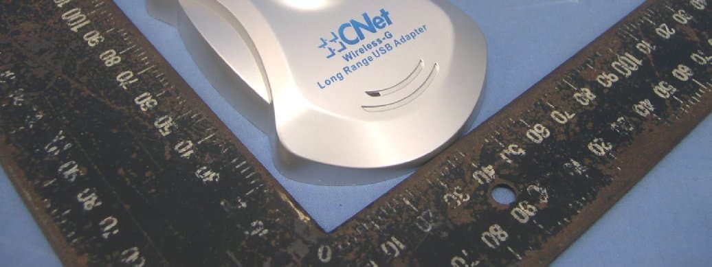
Oct 30, 2007Wireless-G Long Range USB Adapter with Antenna
Equipment Class
DTS - Digital Transmission System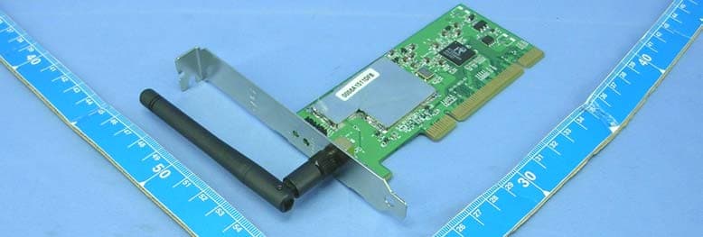
IIO-CWP854
Nov 24, 2004Wireless-G PCI Adapter
Equipment Class
DTS - Digital Transmission System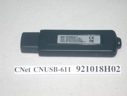
IIO-0343UD
Nov 18, 200311Mbps WLAN USB Dongle
Equipment Class
DTS - Digital Transmission System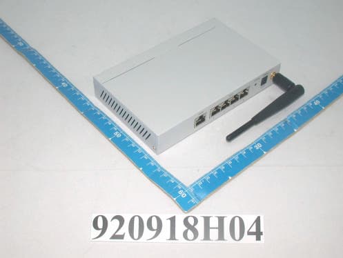
IIO-CNBR914W
Nov 03, 2003Wireless Router
Equipment Class
DTS - Digital Transmission System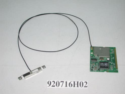
IIO-0328MP
Oct 21, 2003Wireless MiniPCI Module
Equipment Class
DTS - Digital Transmission System