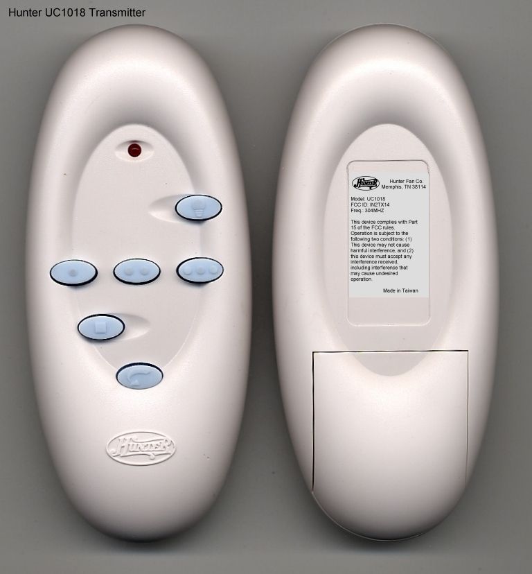
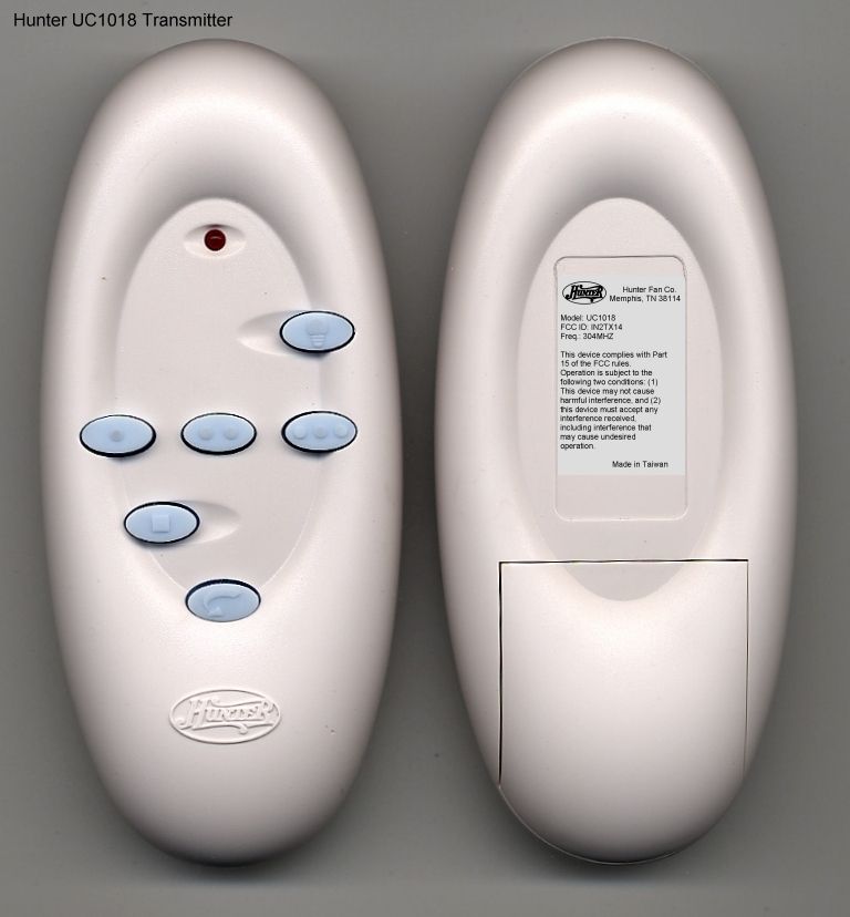
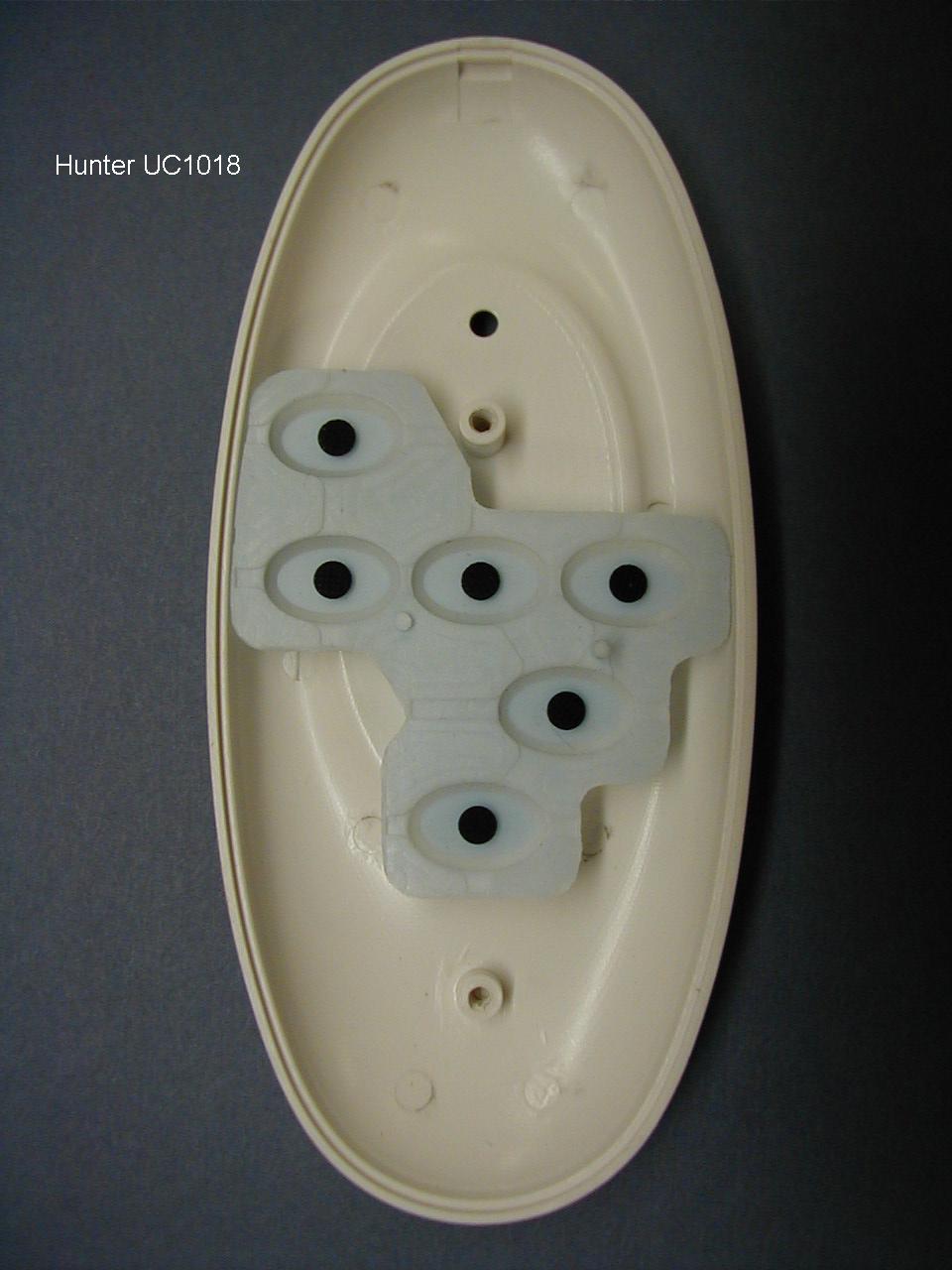
IN2TX14Ceiling fan and lamp remote control.
Hunter Fan Company
Click to zoom
Application Details
- Equipment Class
- DSC - Part 15 Security/Remote Control Transmitter
- Date of Grant
- May 30, 2001
- Application Purpose
- Original Equipment
- Date of Application
- May 30, 2001
- Equipment Note
- Ceiling fan and lamp remote control.
- Frequency Range
- 304.10000000 - 304.10000000
- Company
- Hunter Fan Company
- Country
- United States
Documents & Files
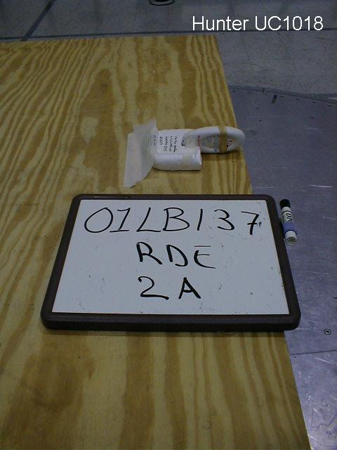
Document Text
Text extracted from the exhibit documents filed with the FCC. Open a document above to read the original.
Users Manual
20 41462-01 04/06/01 ® STEP 9 - REMOTE CONTROLSETTING UNIQUE DIP SWITCHNUMBERSIMPORTANT: Before using this con- trol, change the factory default DIPswitch settings on the Remote andthe Fan, to your own unique code.Refer to Figure 9a, 9b and 9c.Figure 9a Dip Switch Motor Cover Note: All fans leave the factory set to ‘01110’.Note: If this is the second fan in- stalled in the same area, one of thefans MUST have its channel changedfrom ‘01110’ or interference will oc-cur. Make sure that the dip switchsettings in both the second remoteand second fan are set to the samedifferent numbers.CHECKING FAN SETTING1. Remove the three motor cover screws and lift the motor coveroff. 2. Through the view hole on top of the motor, locate the dip switch.Refer to Figure 9a. 3. Check that the dip switch in the fan and the remote are set to thesame unique numbers. 4. Replace the cover and screws.SETTING UNIQUE DIP SWITCHNUMBERSBy changing the sliding switches onthe fan and remote DIP switches,many combinations of unique num-bers can be selected. Refer to Fig-ure 9b. On = 0 and off = 1. DIP Switch Set to01110 DIP Switch Set to01001 Figure 9b 21 41462-01 04/06/01 ® See Figures 9a, 9b, and 9c. Thebattery must be removed whenchanging dip switch settings.Install the included 12 volt alka-line battery (Type 23A, MN-21 orequivalent) inside the remotematching polarity on the Batteryas indicated by the + and - sym-bols in the Battery Compartment.See Figure 9c. REMOTE CRADLE INSTALLATIONSTANDARD LIGHT SWITCH1. Remove the two screws holding the switch cover plate. Do not re-move the cover plate. 2. Orient the control cradle as shown in Figure 9d, and line upthe two inner mounting holeswith those on the switch, insertscrews, don't over tighten. REMOTE SETUP1. Slide the cover off the back of the remote as shown in Figure 9c,pressing in and sliding the coverdown to release. Set the DIPswitches in the Remote to matchthe DIP switches in the receiver. continued Figure 9dROCKER LIGHT SWITCH1. Break off the two tabs by push- ing outward. See Figure 9e. 2. Remove the two screws holding the switch cover plate. Do not re-move the cover plate. 3. Orient the remote cradle as shown in Figure 9e. Line up thetwo outer mounting holes with Figure 9c DIP Switches Battery Compartment Cover Back of Remote Press CoverHere andSlide Down 22 41462-01 04/06/01 ® FanLow Reverse Fan Off FanMedium Fan High Figure 9e those on the switch , insertscrews, don't over tighten. WALL INSTALLATION1. Locate a 2x4 wall stud in a conve- nient location. 2. Orient the remote cradle as shown in Figure 9f, over the 2x4 stud. 3. Use the 1” wood screws in either the inner or outer mounting holes. Note: Wall anchors and 6-32 x 1” screws may be used in situationswhere mounting to a stud is not pos-sible. Use the inner mounting holes. RemoveTab RemoveTab Figure 9g Figure 9fFAN CONTROLRefer to Figure 9g for identificationof control buttons.To start the fan. Press the selectedspeed button to run the fan at thedesired speed. See Figure 9g. OptionalLight AIRFLOW DIRECTIONTo reverse the airflow press the RE-VERSE button. Reverse operates atany speed whether fan is on or off.The fan returns to its set speed afterreversing. 23 41462-01 04/06/01 ® off and on, the user is encouragedto try to correct the interference byone or more of the following mea-sures: • Reorient or relocate the receiving antenna. • Increase the separation between the equipment and receiver. • Connect the equipment into an outlet on a circuit different fromthat to which the receiver is con-nected. • Consult the dealer or an experi- enced radio/TV technician for help.Note: Any changes or modifica- tions to the transmitter or receivernot expressly approved by HunterFan Company may void one’s au-thority to operate this remote con-trol. 3. For use only with electrically re- versible ceiling fans rated at 1.0amp or less, and fan incandescentlight kits rated at 300 watts or less. 4. Not for use with shaded-pole or nonreversible motors. Not recom-mended for use with the HunterOriginal ®. FCC INFORMATION 1. This device complies with Part 15 of the FCC Rules. Operation is subjectto the following two conditions: (1)This device may not cause harmfulinterference, and (2) this devicemust accept any interference re-ceived, including interference thatmay cause undesired operation. 2. This equipment has been tested and found to comply with the lim-its for a Class B digital device, pur-suant to Part 15 of the FCC Rules.These limits are designed to providereasonable protection againstharmful interference in a residen-tial installation. This equipmentgenerates, uses and can radiate ra-dio frequency energy and, if not in-stalled and used in accordance withthe instructions, may cause harm-ful interference to radio communi-cations. However, there is no guar-antee that interference will not oc-cur in a particular installation.If this equipment does cause harm-ful interference to radio or televi-sion reception, which can be deter-mined by turning the equipment OPTIONAL LIGHT CONTROLTurn the light on or off indepen-dently from the fan by pressing theLIGHT button. Keep pressing thebutton in excess of 1 second, it be-comes a dimmer. The light variesfrom ‘bright’ to ‘dim’ over approxi-mately 8 seconds. This sequence willreverse the light when it reaches thebrightest or dimmest level if you con-tinue to hold the LIGHT button. Re-lease the button when the desiredlevel is reached.AUTO RESUMEQuick (pressing less than 1 second)on/off operation of the LIGHT but-ton maintains the desired brightnesslevel set previously.
Block Diagram
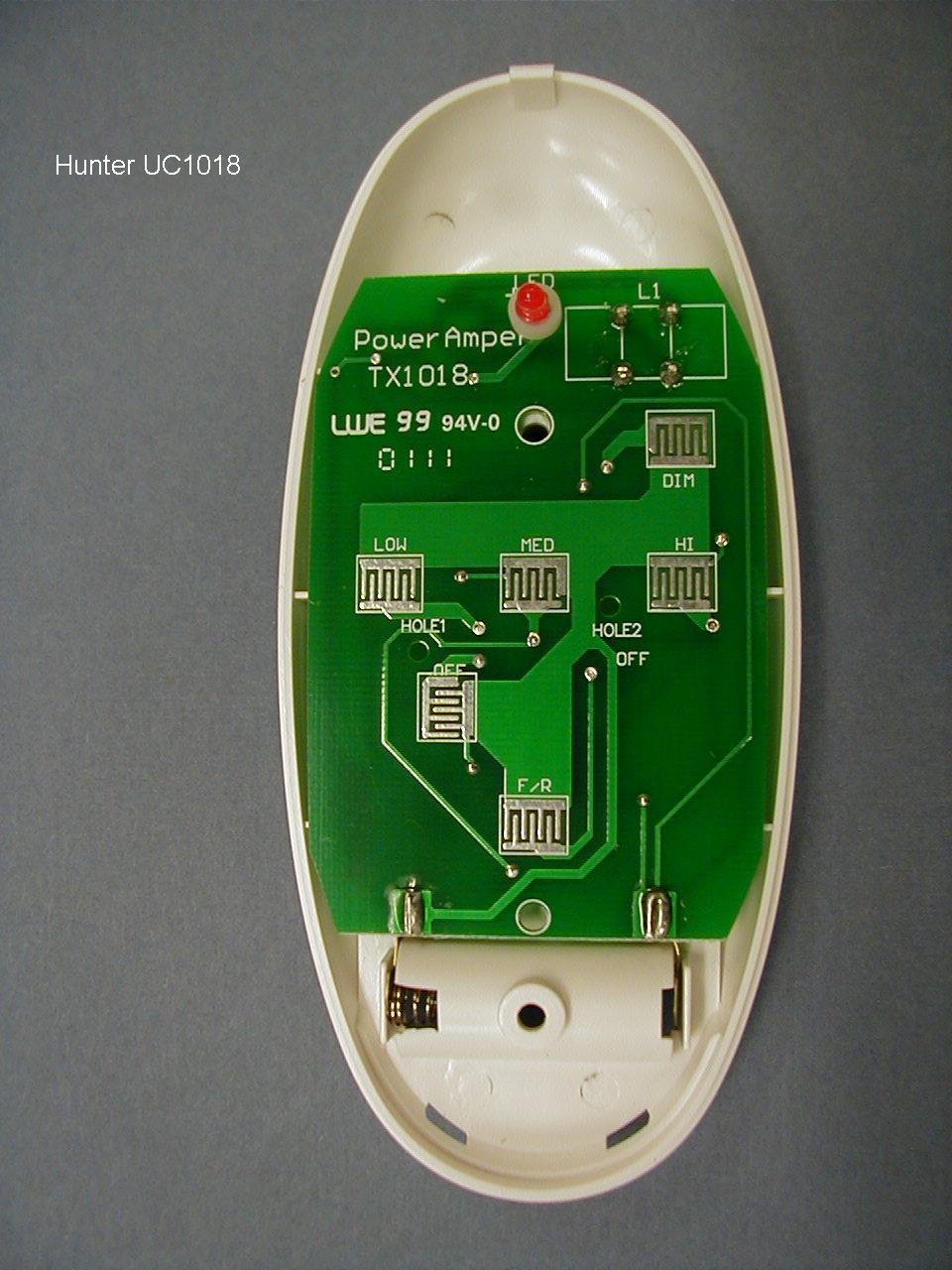
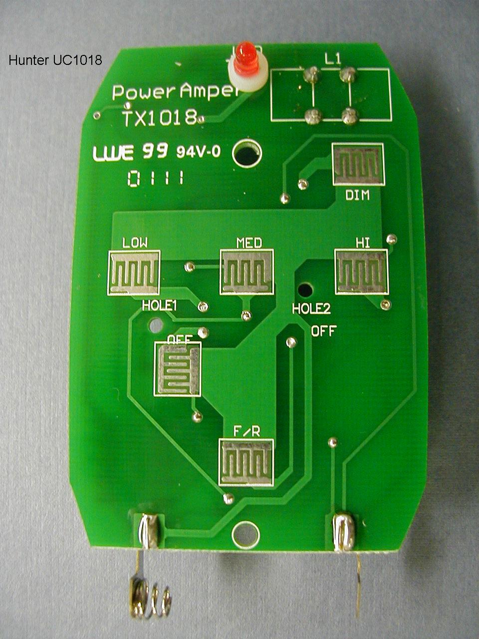
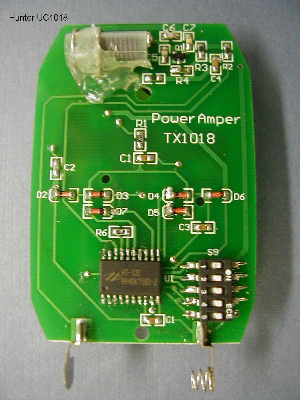
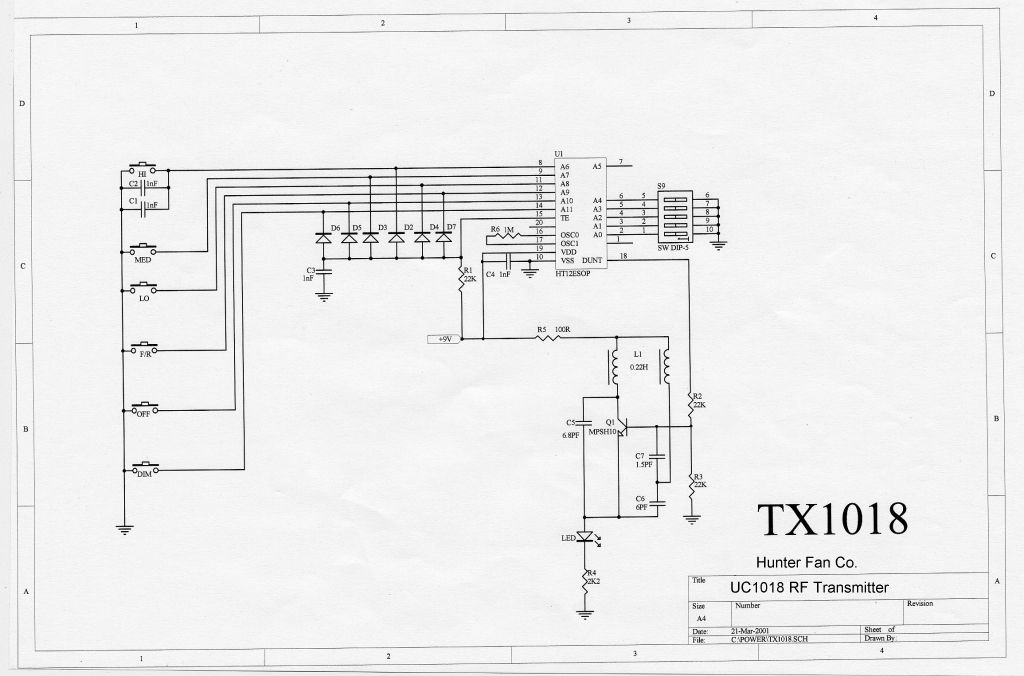
Hunter Fan & Light Remote Control Transmitter Block Diagram Description: The top box of the diagram below represents all of the potential keys that may be pressed for the Hunter UC1018 transmitter. Pressing any key generates an encoded PCM code word which will modulate on a 304 MHz RF carrier for transmission. The encoded PCM code word is obtained from encoder U1 and is ASK modulated by the RF oscillator formed by transistor Q1. Encoder U1 also provides four selectable security bits which can be set by the user. The frequency is factory tuned by inductor L1 to 304 MHz, and is not user adjustable. Antenna Loop UC1018 Transmitter Light Button Fan Low Button Fan Medium Button Fan High Button Fan Off Button Fan Reverse Button U1 Encoder (HT12ESOP) Q1 (MPSH10) ASK Modulator & Oscillator (304 MHz) Factory tuned by L1 (0 ~ .22H) Hunter Fan & Light Remote Control RF Transmitter Coding Description: The UC1018 transmitter uses the following code words to modulate on a 304 MHz RF carrier by using ASK modulation. Examples of code words for different commands: 1xxxxx000101 1xxxxx001001 1xxxxx000110 1xxxxx000111 1xxxxx001000 1xxxxx001101 1xxxxx001110 (Where “x” can be set to “1” or “0” by the user with DIP switches.) Code “0” is represented as: 0.42 ms 0.21ms Code “1” is represented as: 0.21ms 0.42ms The interval between two code words is about 7.56 ms.
Operational Description
Hunter Fan & Light Remote Control Transmitter Block Diagram Description: The top box of the diagram below represents all of the potential keys that may be pressed for the Hunter UC1018 transmitter. Pressing any key generates an encoded PCM code word which will modulate on a 304 MHz RF carrier for transmission. The encoded PCM code word is obtained from encoder U1 and is ASK modulated by the RF oscillator formed by transistor Q1. Encoder U1 also provides four selectable security bits which can be set by the user. The frequency is factory tuned by inductor L1 to 304 MHz, and is not user adjustable. Antenna Loop UC1018 Transmitter Light Button Fan Low Button Fan Medium Button Fan High Button Fan Off Button Fan Reverse Button U1 Encoder (HT12ESOP) Q1 (MPSH10) ASK Modulator & Oscillator (304 MHz) Factory tuned by L1 (0 ~ .22H) Hunter Fan & Light Remote Control RF Transmitter Coding Description: The UC1018 transmitter uses the following code words to modulate on a 304 MHz RF carrier by using ASK modulation. Examples of code words for different commands: 1xxxxx000101 1xxxxx001001 1xxxxx000110 1xxxxx000111 1xxxxx001000 1xxxxx001101 1xxxxx001110 (Where “x” can be set to “1” or “0” by the user with DIP switches.) Code “0” is represented as: 0.42 ms 0.21ms Code “1” is represented as: 0.21ms 0.42ms The interval between two code words is about 7.56 ms.
Test Report
Project: 01RT4338 File: MC1324 Report: 010203 Date: April 17, 2001 Model: UC1018 Test Report On Electromagnetic Compatibility Testing Hunter Fan Memphis, TN USA Copyright 2000 Underwriters Laboratories Inc. Underwriters Laboratories Inc. authorizes the above-named company to reproduce this Report provided it is reproduced in its entirety. Project: 01RT4338Underwriters Laboratories, Inc.Issued: 04/17/01 File: MC1324Test Report on Electromagnetic CompatibilityPage 2 of 53 Test Report: 010203 Test Report Details: Tests Performed By: Underwriters Laboratories Inc. 12 Laboratory Drive Research Triangle Park, NC 27709 Tests Performed For: Hunter Fan 2500 Frisco Avenue Memphis, TN 38114 USA Applicant Contact: Mr. Steve Bias (901) 248-2373 - FAX Test Report Number: 010203 Test Report Date: April 17, 2001 Product Type: Low-power transmitter for Ceiling Fan/Lamp Model Number: UC1018 Sample Serial Number: None Sample Tag Number: S01LB137B EUT Category: Transmitter - Low Power EUT Type: Hand Held Sample Receive Date: March 29, 2001 Testing Start Date: April 04, 2001 Date Testing Complete: April 17, 2001 Underwriters Laboratories Inc. reports apply only to the specific samples tested under stated test conditions. All samples tested were in good operating condition throughout the entire test program. It is the manufacturer's responsibility to assure that additional production units of this model are manufactured with identical electrical and mechanical components. Underwriters Laboratories Inc. shall have no liability for any deductions, inferences or generalizations drawn by the client or others from Underwriters Laboratories Inc. issued reports. This report shall not be used to claim, constitute or imply product certification, approval, or endorsement by NVLAP or any agency of the US government. This report may contain data which is not covered by the NVLAP accreditation. Only data which is noted under Remarks of Summary of Testing as being NVLAP Accredited Data can be considered to be covered by the NVLAP accreditation. Project: 01RT4338Underwriters Laboratories, Inc.Issued: 04/17/01 File: MC1324Test Report on Electromagnetic CompatibilityPage 3 of 53 Test Report: 010203 Summary of Testing: TestTest NameComplyDoes NotSee #Test Requirement/SpecificationComplyRemark 1Radiated Disturbance Emissions - 9 kHz to 30 MHzX- 47 CFR Part 15, Subpart C / 47 CFR Part 15, Subpart C, Section 15.209 2Radiated Disturbance Emissions - 30 MHz to 1000 MHzX- 47 CFR Part 15, Subpart C / 47 CFR Part 15, Subpart C, Section 15.209 and 15.231 3Radiated Disturbance Emissions - Above 1 GHzX- 47 CFR Part 15, Subpart C / 47 CFR Part 15, Subpart C, Section 15.209 and 15.231 4Radiated Disturbance Emissions - Peak-to-Average RatioN/A- 47 CFR Part 15, Subpart C / 47 CFR Part 15, Subpart C, Section 15.231 5Radiated Disturbance Emissions - Occupied BandwidthX- 47 CFR Part 15, Subpart C / 47 CFR Part 15, Subpart C, Section 15.231 6Radiated Disturbance Emissions - Restricted BandsX- 47 CFR Part 15, Subpart C / 47 CFR Part 15, Subpart C, Section 15.205 Remarks: 1)The data contained herein can also be considered applicable to Canada RSS-210, Section 6.1.1 (Momentarily Operated Devices). 2)The test setup photo in Test 1 applies to its transmit test-case and the idle test-cases of Tests 2 and 3; The test setup photo in Test 2 applies to its transmit test-case and the transmit test-case of Test 3. 3)The device's antenna is permanently attached and no other antenna can be used with it. Conclusion: The tests listed in the Summary of Testing section of this report have been performed and the results recorded by Underwriters Laboratories Inc. in accordance with the procedures stated in each test requirement and specification. The test list was determined by the Applicant as being applicable to the Equipment Under Test. As a result, the subject product has been verified to comply or not comply as noted in the Summary of Testing with each test specification. The test results relate only to the items tested. Project: 01RT4338Underwriters Laboratories, Inc.Issued: 04/17/01 File: MC1324Test Report on Electromagnetic CompatibilityPage 4 of 53 Test Report: 010203 Test Facilities: Test Location A) 10-Meter Anechoic Chamber (Industry Canada - IC 2953, NVLAP - 200246-0, VCCI - R-722) Constructed by Lindgren RF Enclosures, this room consists of a 17.9 by 12 by 8.3 m (inside clearance) shielded room lined with TDK absorber material. The walls, floor (conducting ground plane) and ceiling are constructed of double sided galvanized sheet steel supported by 19 mm thick particle board. The interior walls and ceiling are covered with 10 by 10 cm, 4.6 mm thick ferrite tiles and partially covered with polystyrene absorber cones. Removable floor tiles and cones covering the floor between the EUT and antenna are provided when RF immunity testing is performed. Room is provided with a 4.0 m diameter embedded turntable and a 1.2 by 2.1 m and 2.4 by 2.4 m double knife edge doors for access. Also, the room is fed electrical EUT power via permanently installed filters and is provided with a permanently mounted video surveillance camera. A remotely controllable antenna mast is located in the room for positioning the measuring antenna from 1 to 4 m above the ground plane. Test Location B) Compact Anechoic Chamber Constructed by Lindgren RF Enclosures, this room consists of a 6 by 3 by 2.9 m (inside clearance) shielded room lined with TDK absorber material. The walls, floor (conducting ground plane) and ceiling are constructed of double sided galvanized sheet steel supported by 19 mm thick particle board. The interior walls and ceiling are covered with 10 by 10 cm, 4.6 mm thick ferrite tiles and partially covered with polystyrene absorber cones. Removable floor tiles and cones covering the floor between the EUT and antenna are provided when RF immunity testing is performed. Room is provided with a 1.5 m diameter embedded turntable and a 1.2 by 2.1 m double knife edge …
Text truncated - open the document above for the full version.
Contact Information
Applicant
Julian A Martin(Compliance Manager)
Technical Contact
Underwriters Laboratories Inc.Mark N Nolting
[email protected](919) 549-1584
12 Laboratory Drive · Research Triangle Park, North Carolina · United States
Non-Technical Contact
Underwriters Laboratories Inc.Mark N Nolting
[email protected](919) 549-1584
Test Firm
UL LLCRick Titus
Technical Specifications
| # | Rule Parts | Frequency Range | Power Output | Emission |
|---|---|---|---|---|
| 1 | 15.231 | 304.1 MHz - 304.1 MHz | - | L1D46K8 |
Other Applications from Hunter Fan Company
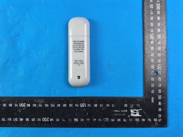
IN2TX61
Sep 11, 2024Remote Control for Ceiling Fan
Equipment Class
DSC - Part 15 Security/Remote Control Transmitter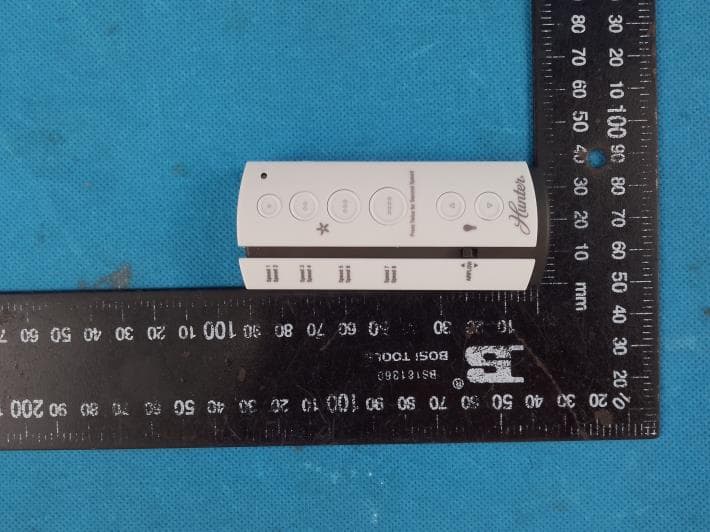
IN2TX57
Jul 03, 2023Remote Control for Ceiling Fan
Equipment Class
DSC - Part 15 Security/Remote Control Transmitter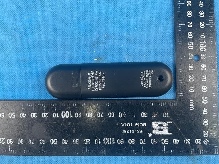
IN2TX52
Jan 10, 2023Remote Control for Ceiling Fan
Equipment Class
DSC - Part 15 Security/Remote Control Transmitter
IN2TX50
Jul 29, 2020Remote Control for Ceiling Fan
Equipment Class
DSC - Part 15 Security/Remote Control Transmitter
IN2TX49
Jun 14, 2020Remote control for ceiling fan
Equipment Class
DSC - Part 15 Security/Remote Control Transmitter