IN2TX57Remote Control for Ceiling Fan
Hunter Fan Company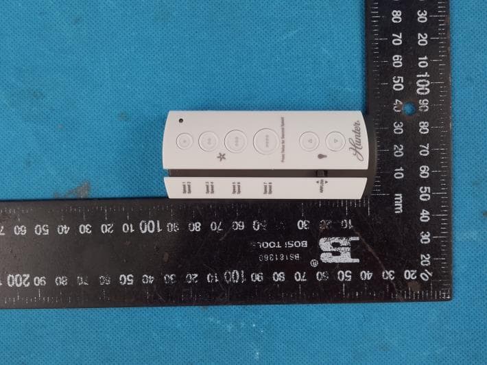
Click to zoom
Application Details
- Equipment Class
- DSC - Part 15 Security/Remote Control Transmitter
- Date of Grant
- Jul 03, 2023
- Application Purpose
- Original Equipment
- Date of Application
- Jul 03, 2023
- Equipment Note
- Remote Control for Ceiling Fan
- Frequency Range
- 433.92000000 - 433.92000000
- Company
- Hunter Fan Company
- Country
- United States
Documents & Files
Document Text
Text extracted from the exhibit documents filed with the FCC. Open a document above to read the original.
Users Manual
www.CasablancaFanCo.com 1.888.227.2178 M6009-01 • 05/18/15 • © 2012–2015 Casablanca Fan Company Model 99019 Universal Remote Control Transmitter & Receiver Installation OROROR OFF Remove the canopy. If uncertain how to remove it, reference the fan’s owner’s manual. With wiring exposed, it may be helpful to note existing wire connections or take a digital photo for reference. Remove the wire connectors that were connecting the wires from the outlet box to the fan, leaving the grounding wires connected. Before installing the Universal Remote Control Receiver, use the pull chains to set the fan speed to HIGH and the light to ON. Be sure power is OFF before proceeding with installation. Choose the hanging system that most closely resembles the one used by your fan and install the receiver and wire as directed. Note: Some fans may have considerable excess lead wire. For easier canopy installation, cut the excess wire, leaving a minimum of 8” remaining. Re-strip the fan lead wires 1/2”. Place remaining excess wire into the ceiling electrical box. The bracket and fan must remain properly grounded. This Remote Control Transmitter and Receiver is not compatible with Casablanca Hang Tru® Canopy Systems. You may have installation issues if the fan is installed on an angled ceiling. Ceiling Plate Receive r Canopy Receiver Canopy Ceiling Bracket Receiver Fan Body Cable Tie Receiver Canopy For low profile fans, the receiver should be secured to the ceiling bracket with a cable tie. Wiring CONNECT WIRES FROM RECEIVER TO FAN - Using the orange wire connectors, connect the blue wire from the receiver to the blue wire (or possibly black with white stripe wire) from the fan. Connect the yellow wire from the receiver to the black wire from the fan. If you’re uncertain about wire colors or connections, please contact a qualified electrician. CONNECT WIRES FROM RECEIVER AND FAN TO WIRES FROM OUTLET BOX - Using the orange wire connectors, connect the black wire (ungrounded) from the ceiling to the black wire from the receiver. Connect the white wire (grounded) from the ceiling to both the white wire from the receiver and the white wire from the fan. AFTER ALL WIRES ARE CONNECTED and secured with wire connectors, re-install the canopy. Turn the splices upward and push them carefully back through the hanger bracket into the outlet box. Spread the wires apart, with the grounded wires on one side of the outlet box and the ungrounded wires on the other side of the outlet box. To avoid possible electrical shock, before installing or servicing your fan, disconnect the power by turning off the circuit breakers to the outlet box and associated wall switch location. If you cannot lock the circuit breakers in the off position, securely fasten a prominent warning device, such as a tag, to the service panel. F R O M C E I L I N G F R O M R E C E I V E R black blue yellow blue F R O M F A N F R O M R E C E I V E R black white white (grounded) black (ungrounded) white F R O M F A N www.CasablancaFanCo.com 1.888.227.2178 M6009-01 • 05/18/15 • © 2012–2015 Casablanca Fan Company TroubleshootingSafe-Exit AUTHORIZED SERVICE CENTERS For the most updated listing of Casablanca Authorized Service Centers, visit www.CasablancaFanCo.com or call toll free 1-888-227-2178. ONE YEAR WARRANTY This product is warranted to the original purchaser by Casablanca Fan Company against defects in material and workmanship for one (1) year from date of purchase. During the warranty period, we will repair or, at our option, replace a defective product at no charge. For information on how to obtain service, contact Casablanca’s Service Department by calling our toll-free number at 1-888-227-2178. Damage to the product caused by mishandling, improper installation or modification is not covered by this warranty. This warranty is given in lieu of all other warranties expressed or implied. Some states do not allow limitations of time on an implied warranty, therefore the above limitations may not apply in every case. This warranty states specific legal rights which may vary from state to state. If you have problems installing or operating your fan, do not return this product to the dealer. Call our Consumer Affairs Hotline. 1-888-227-2178 This device complies with RSS-210 of Industry Canada. Operation is subject to the following two conditions: (1) this device may not cause interference, and (2) this device must accept any interference, including interference that may cause undesired operation of the device. 1. This device complies with part 15 of the FCC Rules. Operation is subject to the following two conditions: (1) this device may not cause harmful interference, and (2) this device must accept any interference received, including interference that may cause undesired operation. 2. This equipment has been tested and found to comply with the limits for a Class B digital device, pursuant to Part 15 of the FCC Rules. These limits are designed to provide reasonable protection against harmful interference in a residential installation. This equipment generates, uses and can radiate radio frequency energy and, if not installed and used in accordance with the instructions, may cause harmful interference to radio communications. However there is no guarantee that interference will not occur in a particular installation. If this equipment does cause harmful interference to radio or television reception, which can be determined by turning the equipment off and on, the user is encouraged to try to correct the interference by one or more of the following measures: Reorient or relocate the receiving antenna, Increase the separation between the equipment and receiver, Connect the equipment into an outlet on a circuit different from that to which the receiver is connected. Consult the dealer or an experienced radio/TV technician for help. Note: Any changes or modifications to the transmitter or receiver not expressly approved by Casablanca Fan Company may void one’s au…
Text truncated - open the document above for the full version.
Attestation Statements
Hunter Fan Company * the applicant must designate a contact located in the United States for purposes of acting as the applicant’s agent for service of process, regardless of whether the applicant is a domestic or foreign entity. An applicant located in the United States may designate itself as the agent for service of process. U.S. Agent Designation for Service of Process - Certification Attestation Letter June 5, 2023 Nemko North America, Inc. 303 River Road Ottawa K1V 1H2 Canada ATTN.: Reviewing Engineer FCC ID: IN2TX57 FRN: 0006777569 Per section 2.911(d)(7) of the FCC rules, Hunter Fan Company (“the applicant”) certifies that the equipment for which authorization is sought is designated to the following U.S. Designated agent* for service of process: Company Name: Hunter Fan Company Physical U.S. Company Address: 7130 Goodlett Farms Pkwy, Suite 400, Memphis, TN 38016 Agent name: Julian Martin Agent Email Address: [email protected] FRN: 0006777569 The above contact person accepts the obligation for service of process. The applicant accepts to maintain an agent for no less than one year after the grantee has terminated all marketing and importation or the conclusion of any Commission-related proceeding involving the equipment. Applicant Signed: Designated Agent Signed: (Required, if different to Applicant): Signed: Signed: Printed name: Julian Martin Printed name: Julian Martin Title: Compliance Manager Title: Compliance Manager Company Name: Hunter Fan Company Company Name: Hunter Fan Company Date: June 2, 2023 Date: June 2, 2023
Attestation Statements
Hunter Fan Company Covered Equipment Certification Attestation Letter 6/2/2023 Nemko North America, Inc. 303 River Road Ottawa K1V 1H2 Canada ATTN.: Reviewing Engineer FCC ID: IN2TX57 (Hunter Fan Company) certifies that the equipment for which authorization is sought is not “covered” equipment prohibited from receiving an equipment authorization pursuant to section 2.903 of the FCC rules. Note: If the equipment for which the applicant seeks authorization is produced by any of the entities identified on the current Covered List, the applicant should include an explanation on why the equipment is not “covered” equipment. (Hunter Fan Company) certifies that, as of the date of the filing of the application, the applicant is not identified on the Covered List as an entity producing “covered” equipment. Signed: Printed name: Julian Martin Title: Compliance Manager Company Name: Hunter Fan Company Date: 6/2/2023
Cover Letter(s)
2023-05-24 Nemko Canada Inc 303 River Road Ottawa, Ontario, Canada K1V 1H2 Attn: Director of Certification Authority to Act as Agent On our behalf, I appoint Shenzhen Huatongwei International Inspection Co., Ltd./ 1/F, Bldg 3, Hongfa Hi-tech Industrial Park, Genyu Road, Tianliao, Gongming, Shenzhen, China / Hans Hu,. to act as our agent in the preparation of this application for equipment certification. I certify that submitted documents properly describe the device or system for which equipment certification is sought. I also certify that each unit manufactured, imported or marketed, as defined in the Federal Communications Commission’s regulations will have affixed to it a label identical to that submitted for approval with this application. For instances where our authorized agent signs the application for certification on our behalf, I acknowledge that all responsibility for complying with the terms and conditions for certification, as specified by Nemko Canada Inc, still resides with Hunter Fan Company / 7130 Goodlett Farms Pkwy, Suite 400, Memphis Tennessee 38016 United States. Agency agreement expiration date: 2024-05-24 By: Julian Martin Signature Printed On behalf of : Hunter Fan Company Telephone: 901-248-2810
Cover Letter(s)
2023-06-02 Equipment Autorisation Division Federal Communications Commission 7435 Oakland Mills Road Columbia, MD 21046 FCC ID: IN2TX57 Product Name: Remote Control for Ceiling Fan Request for Confidentiality Pursuant to Sections 0.457 and 0.459 of the commissions rules, we hereby request that the following documents be held confidential: Schematics Block diagram Operation description These materials contain trade secrets and proprietary information and are not customarily released to the public. The public disclosure of this information might be harmful to the company and provide unjustified benefits to our competitors. By: Julian Martin Signature Printed On behalf of : Hunter Fan Company Telephone: 901-248-2810
Cover Letter(s)
Differences Declaration To whom concern, We company Hunter Fan Company Here by declares: The product model(s) G1764-A1-000 is the same PCB layout, electronic schematic and Antenna with G1764-A2-000, J0250-A1 which tested in Shenzhen Huatongwei International Inspection Co., Ltd. They are the same model that has 3 names, the EUT has different appearance and silk screen is different. See the table below for details: Sincerely yours, Signature: Name: Julian Martin Company name: Hunter Fan Company Company address: 7130 Goodlett Farms Parkway, Ste 400 Cordova, TN 38016-4991 USA E-Mail: [email protected]
Cover Letter(s)
Statement Letter All measurements were performed radiated and therefore additional antenna gain documentation is not required. By: Julian Martin Signature Printed On behalf of : Hunter Fan Company Telephone: 901-248-2810
External Photos
External Photos G1764-A1-000 G1764-A2-000 J0250-A1
Internal Photos
Internal Photos G1764-A1-000 G1764-A2-000 J0250-A1
RF Exposure Info
FCC ID: IN2TX57 RF Exposure Evaluation REQUIREMENT KDB447498 D01 General RF Exposure Guidance v06, Clause 4.3.1(a) a) For 100 MHz to 6 GHz and test separation distances ≤ 50 mm, the 1-g and 10-g SAR test exclusion thresholds are determined by the following: [(max. power of channel, including tune-up tolerance, mW) / (min. test separation distance, mm)] · [√f(GHz)] ≤ 3.0 for 1-g SAR, and ≤ 7.5 for 10-g extremity SAR, where -f(GHz) is the RF channel transmit frequency in GHz -Power and distance are rounded to the nearest mW and mm before calculation -The result is rounded to one decimal place for comparison -The values 3.0 and 7.5 are referred to as numeric thresholds in step b) below The test exclusions are applicable only when the minimum test separation distance is ≤ 50 mm, and for transmission frequencies between 100 MHz and 6 GHz. When the minimum test separation distance is < 5 mm, a distance of 5 mm according to 4.1 f) is applied to determine SAR test exclusion. b) For 100 MHz to 6 GHz and test separation distances > 50 mm, the 1-g and 10-g SAR test exclusion thresholds are determined by the following (also illustrated in Appendix B): 1) {[Power allowed at numeric threshold for 50 mm in step a)] + [(test separation distance – 50 mm)·(f(MHz)/150)]} mW, for 100 MHz to 1500 MHz 2) {[Power allowed at numeric threshold for 50 mm in step a)] + [(test separation distance – 50 mm)·10]} mW, for > 1500 MHz and ≤ 6 GHz c) For frequencies below 100 MHz, the following may be considered for SAR test exclusion (also illustrated in Appendix C): 1) For test separation distances > 50 mm and < 200 mm, the power threshold at the corresponding test separation distance at 100 MHz in step b) is multiplied by [1 + log(100/f(MHz))] 2) For test separation distances ≤ 50 mm, the power threshold determined by the equation in c) 1) for 50 mm and 100 MHz is multiplied by ½ 3) SAR measurement procedures are not established below 100 MHz. When SAR test exclusion cannot be applied, a KDB inquiry is required to determine SAR evaluation requirements for any SAR test results below 100 MHz to be acceptable. TEST RESULT Passed Not Applicable Test Frequency H-field strength (dBuV/m) H-field strength (dBm) H-field strength (mW) Limit (mW) Result 433.92MHz 75.73 -19.47 0.0113 3.0 Pass Note: 1) The exposure evaluation safety distance is 5mm. 2) (dBm)=E(dBuV/m)+20log(d)-104.77=E(dBuV/m)-95.2
Test Report
Page: 1 of 34 TEST REPORT For RF Report No. ...................................... : CHTEW23050066 Report Verification: Project No.................................: SHT2305029301EW FCC ID ............................................. : IN2TX57 Applicant’s name ........................... : Hunter Fan Company Address ............................................. : 7130 Goodlett Farms Pkwy, Suite 400, Memphis Tennessee 38016 United States Product Name ................................ : Remote Control for Ceiling Fan Trade Mark ....................................... : Hunter Model No. ......................................... : G1764-A1-000 Listed Model(s) ................................. : G1764-A2-000,J0250-A1 Standard ......................................... : FCC CFR Title 47 Part 15 Subpart C § 15.231 Date of receipt of test sample..........: May 16, 2023 Date of testing.............................: May 16, 2023- May 25, 2023 Date of issue...............................: May 26, 2023 Result .................. ........................: PASS Compiled by (Position+Printed name+Signature): File administrator Fanghui Zhu Supervised by (Position+Printed name+Signature): Project Engineer Kiki Kong Approved by (Position+Printed name+Signature): RF Manager Hans Hu Testing Laboratory Name ............. : Shenzhen Huatongwei International Inspection Co., Ltd. Address ............................................. : 1/F, Bldg 3, Hongfa Hi-tech Industrial Park, Genyu Road, Tianliao, Gongming, Shenzhen, China Shenzhen Huatongwei International Inspection Co., Ltd. All rights reserved. This publication may be reproduced in whole or in part for non-commercial purposes as long as the Shenzhen Huatongwei International Inspection Co., Ltd. is acknowledged as copyright owner and source of the material. Shenzhen Huatongwei International Inspection Co., Ltd. takes no responsibility for and will not assume liability for damages resulting from the reader's interpretation of the reproduced material due to its placement and context. The test report merely correspond to the test sample. Report No.: CHTEW23050066 Page: 2 of 34 Date of issue: 2023-05-26 Shenzhen Huatongwei International Inspection Co., Ltd. Report Template Version: V05 (2023-03) Contents 1. TEST S T AN D AR D S A N D R E P O R T V E R S ION 3 1.1. Test Standards 3 1.2. Report version 3 2. TEST DESCRIPTION 4 3. SUMMARY 5 3.1. Client Information 5 3.2. Product Description 5 3.3. Radio Specification Description 5 3.4. Testing Laboratory Information 5 4. TEST CONFIGURATION 6 4.1. Test frequency list 6 4.2. Descriptions of Test mode 6 4.3. Test sample information 6 4.4. Support unit used in test configuration and system 7 4.5. Testing environmental condition 7 4.6. Statement of the measurement uncertainty 7 4.7. Equipment Used during the Test 8 5. TEST CONDITIONS AND RESULTS 9 5.1. Antenna Requirement 9 5.2. AC Conducted Emission 10 5.3. 20dB bandwidth 11 5.4. 99% Occupied Bandwidth 12 5.5. Transmission Time 13 5.6. Duty Cycle Corrected Factor 14 5.7. Radiated field strength of the fundamental signal 15 5.8. Radiated Spurious Emission 17 6. TEST SETUP PHOTOS 23 7. EXTERNAL AND INTERNAL PHOTOS 24 7.1. External Photos 24 7.2. Internal Photos 30 8. APPENDIX REPORT 34 Report No.: CHTEW23050066 Page: 3 of 34 Date of issue: 2023-05-26 Shenzhen Huatongwei International Inspection Co., Ltd. Report Template Version: V05 (2023-03) 1. TEST STAND ARDS AND REPORT VERSION 1.1. Test Standards The tests were performed according to following standards: ‒ FCC CFR Title 47 Part 15 Subpart C § 15.231: Periodic operation in the band 40.66-40.70 MHz and above 70 MHz ‒ ANSI C63.10:2013: American National Standard for Testing Unlicensed Wireless Devices 1.2. Report version Revision No. Date of issue Description N/A 2023-05-26 Original Report No.: CHTEW23050066 Page: 4 of 34 Date of issue: 2023-05-26 Shenzhen Huatongwei International Inspection Co., Ltd. Report Template Version: V05 (2023-03) 2. TEST DESCRIPTION Report clause Test Items Standard Requirement Result Test Engineer 5.1 Antenna Requirement 15.203 PASS Xiaoqin Li 5.2 AC Conducted Emission 15.207 N/A N/A 5.3 20dB Bandwidth 15.231(c) PASS Xiaoqin Li 5.4 99% Occupied Bandwidth - PASS *1 Xiaoqin Li 5.5 Transmission time 15.231(a)(1) PASS Xiaoqin Li 5.6 Duty cycle corrected factor - PASS *1 Xiaoqin Li 5.7 Field strength of the Fundamental signal 15.231(b) PASS Yifan Wang 5.8 Radiated Spurious Emission 15.231(b)/15.205/15.209 PASS Yifan Wang Note: ‒ The measurement uncertainty is not included in the test result. ‒ *1: No requirement on standard, only report these test data. Report No.: CHTEW23050066 Page: 5 of 34 Date of issue: 2023-05-26 Shenzhen Huatongwei International Inspection Co., Ltd. Report Template Version: V05 (2023-03) 3. SUMMARY 3.1. Client Information Applicant: Hunter Fan Company Address: 7130 Goodlett Farms Pkwy, Suite 400, Memphis Tennessee 38016 United States Manufacturer: Hunter Fan Company Address: 7130 Goodlett Farms Pkwy, Suite 400, Memphis Tennessee 38016 United States Factory: Shenzhen H&T Iintelligent Control CO., Ltd. Address: H&T Industrial Park,No.18 BaoShan Road,Tian Liao Community,Guangming new district,Shenzhen,Guangdong,China 518132 3.2. Product Description Main unit information: Product Name: Remote Control for Ceiling Fan Trade Mark: Hunter Model No.: G1764-A1-000 Listed Model(s): G1764-A2-000,J0250-A1 Power supply: DC 3V from Battery Hardware version: V01 Software version: V01 3.3. Radio Specification Description Operation frequency: 433.92MHz Modulation: OOK Channel number: 1 Antenna type: PCB Antenna 3.4. Testing Laboratory Information Laboratory Name Shenzhen Huatongwei International Inspection Co., Ltd. Laboratory Location 1/F, Bldg 3, Hongfa Hi-tech Industrial Park, Genyu Road, Tianliao, Gongming, Shenzhen, China Contact information: Phone: 86-755-26715499 E-mail: [email protected] http://www.szhtw.com.cn Qualifications Type Accreditation Number FCC 762235 Report No.: CHTEW23050066 …
Text truncated - open the document above for the full version.
Test Report
Project No.: SHT2305029301EW Shenzhen Huatongwei International Inspection Co., Ltd. Appendix report page: 1 of 6 APPENDIX REPORT Project No. SHT2305029301EW Test sample No. YPHT23050293001 Model No. G1764-A1-000 Start test date 2023-05-16 Finish date 2023-05-16 Temperature 25.1°C Humidity 68% Test Engineer Xiaoqin Li Auditor Appendix clause Test item Result A 20dB Bandwidth PASS B 99% Occupied Bandwidth PASS C Deactivation Time PASS D Duty Cycle Corrected Factor PASS Project No.: SHT2305029301EW Shenzhen Huatongwei International Inspection Co., Ltd. Appendix report page: 2 of 6 Appendix A:20dB bandwidth Test Channel 20dB Bandwidth (kHz) Limit (kHz) Result CH M 9.99 1084.8 Pass NOTE:Limit=0.25%*Center Frequency=1084.8 kHz CH M Project No.: SHT2305029301EW Shenzhen Huatongwei International Inspection Co., Ltd. Appendix report page: 3 of 6 Appendix B:99% Occupied Bandwidth Test Channel 99% Occupied Bandwidth (kHz) Limit (kHz) Result CH M 28.51 - Pass CH M Project No.: SHT2305029301EW Shenzhen Huatongwei International Inspection Co., Ltd. Appendix report page: 4 of 6 Appendix C:Deactivation Time Transmission time (second) Limit (second) Result 0.21 5 Pass CH M Project No.: SHT2305029301EW Shenzhen Huatongwei International Inspection Co., Ltd. Appendix report page: 5 of 6 Appendix D:Duty Cycle Corrected Factor T ON1 (ms) : 0.435 T ON1 number 45 T ON2 (ms) : 0.87 T ON2 number 33 Period (ms) : 100 Duty Cycle : 48.285% Duty Cycle Corrected Factor: -6.32 Note: 1) Duty cycle= Ton1* T ON1 number +Ton2* T ON2 number / Tperiod 2) Duty Cycle Corrected Factor/DCCF=20*log (Duty Cycle) Project No.: SHT2305029301EW Shenzhen Huatongwei International Inspection Co., Ltd. Appendix report page: 6 of 6 T ON1 (ms) : T ON2 (ms) : Period (ms) : --------End of Report--------
Test Setup Photos
TEST SETUP PHOTOS Radiated Emission
Contact Information
Applicant
Julian A Martin(Compliance Manager)
Test Firm
Shenzhen Huatongwei International Inspection Co.,Tony Jiang
[email protected]+86-755-26748078
Technical Specifications
| # | Rule Parts | Frequency Range | Power Output |
|---|---|---|---|
| 1 | 15.231 | 433.92 MHz - 433.92 MHz | - |
Other Applications from Hunter Fan Company
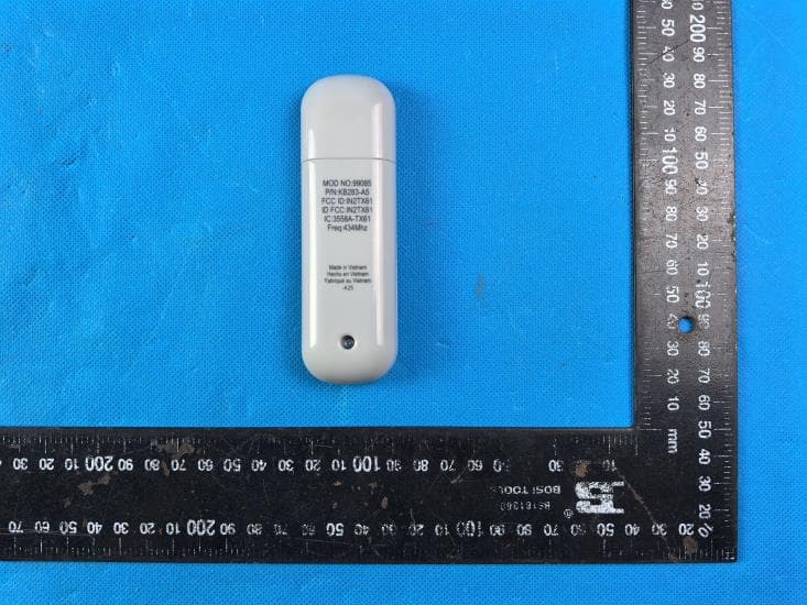
IN2TX61
Sep 11, 2024Remote Control for Ceiling Fan
Equipment Class
DSC - Part 15 Security/Remote Control Transmitter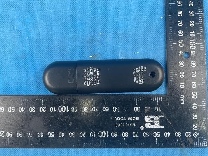
IN2TX52
Jan 10, 2023Remote Control for Ceiling Fan
Equipment Class
DSC - Part 15 Security/Remote Control Transmitter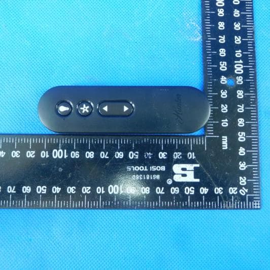
IN2TX50
Jul 29, 2020Remote Control for Ceiling Fan
Equipment Class
DSC - Part 15 Security/Remote Control Transmitter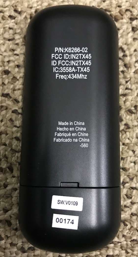
IN2TX49
Jun 14, 2020Remote control for ceiling fan
Equipment Class
DSC - Part 15 Security/Remote Control Transmitter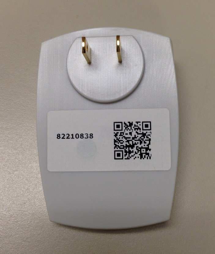
IN2TX44
Mar 17, 2015Plug in remote control for ceiling fan
Equipment Class
DSC - Part 15 Security/Remote Control Transmitter