IN2TX15Univeral Video & Fan Remote Control Transmitter
Hunter Fan Company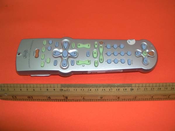
Click to zoom
Application Details
- Equipment Class
- DXX - Part 15 Low Power Communication Device Transmitter
- Date of Grant
- Feb 20, 2002
- Application Purpose
- Original Equipment
- Date of Application
- Feb 20, 2002
- Equipment Note
- Univeral Video & Fan Remote Control Transmitter
- Frequency Range
- 350.00000000 - 350.00000000
- Company
- Hunter Fan Company
- Country
- United States
Documents & Files
Document Text
Text extracted from the exhibit documents filed with the FCC. Open a document above to read the original.
Users Manual
41536-01 1/25/20021 Ceiling Fan & Video Universal Remote Control Owner’s Manual Hunter Fan Company ® 241536-01 1/25/2002 READ AND SAVE THESE INSTRUCTIONS Caution: Risk of Electrical Shock! Transmitter Model No. 27177 This device complies with part 15 of the FCC rules. Changes or modifications not expressly approved by Hunter Fan Company could void your authority to operate this equipment! Operation Is Subject To The Following Two Conditions: 1. This device may not cause harmful interference. 2. This device must accept any interference received, including interference that may cause undesired operation. This equipment has been tested and found to comply with the limits for a Class B digital device, pursuant to Part 15 of the FCC Rules. These limits are designed to provide reasonable protection against harmful interference in a residential installation. This equipment generates, uses and can radiate radio frequency energy and, if not installed and used in accordance with the instructions, may cause harmful interference to radio communications. However, there is no guarantee that interference will not occur in a particular installation. If this equipment does cause harmful interference to radio or television reception, which can be determined by turning the equipment off and on, the user is encouraged to try to correct the interference by one or more of the following measures: • Reorient or relocate the receiving antenna. • Increase the separation between the equipment and receiver. • Connect the equipment into an outlet on a circuit different from that to which the receiver is connected. • Consult the dealer or an experienced radio/TV technician for help. Note: Any changes or modifications to the transmitter or receiver not expressly approved by Hunter Fan Company may void one’s authority to operate this remote control. Not for use with shaded-pole or non-reversible motors. Not recommended for use with the Hunter Original®. ® 2002 Hunter Fan Company 41536-01 1/25/20023 table of contents setting up your remote control .................................. 4 installing your batteries ......................................................... 4 setting your remote dip switches .......................................... 4 programming your device code ............................................ 5 testing your device code........................................................ 5 checking your device code .................................................... 6 searching for your device code............................................. 6 TV brand codes....................................................................... 7 VCR brand codes .................................................................. 10 DVD brand codes .................................................................. 12 cable brand codes................................................................ 12 satellite brand codes............................................................ 13 operating your remote control ................................. 14 power and device button functions..................................... 14 menu button functions......................................................... 15 channel and volume button functions ................................ 16 VCR and DVD button functions ........................................... 17 number keypad button functions ........................................ 18 fan button functions ............................................................. 19 troubleshooting......................................................... 20 warranty..................................................................... 22 441536-01 1/25/2002 setting up your remote control installing your batteries 1. Remove the battery cover. 2. Install 4 AA alkaline batteries. setting your remote dip switches Your dip switches control the radio frequency signal that is used to control your Hunter ceiling fan. The dip switches in the remote should be the same as the dip switches/pin jumpers in the receiver that is installed in your Hunter ceiling fan. 1. Set the dip switches in the remote to the same code as the dip switches in the receiver. 2. Replace the battery cover. Dip Switches 41536-01 1/25/20025 programming your device code 1. Manually turn on your device. 2. On your Hunter Universal Video & Fan Remote, press and hold the device button for 3 seconds. The red indicator light comes on and goes off. 3. Release the device button. The red indicator light comes on as you release the device button. 4. Press the 4 digit code listed for your device brand on pages 7-13. The red indicator light should go off when pressing a button and come on when the button is released. 5. The red indicator light should flash 3 times to indicate that the code was successfully entered. The remote then exits to the normal operating mode. testing your device code 1. Press and release the device button. 2. Press and release the POWER button. 3. If your device does not turn off, start over with programming your device code and try the next code listed for your device brand. If you are still unable to find a code, try searching for your device code. If you are unable to program your device, feel free to contact Hunter Customer Service for assistance at 1-888-830-1326. 4. Once you have found the code that works for your device, write the code in the space provided. 0 9 8 7 654 312 POWER TV VCR DVD CBL/SAT TV VCR DVD CBL/SAT setting up your remote control CBL/SAT DVD VCR TV 641536-01 1/25/2002 TV VCR DVD CBL/SAT TV VCR DVD CBL/SAT POWER setting up your remote control checking your device code 1. Press and hold the device button for 3 seconds. The red indicator light comes on and goes off. 2. Release the device button. The red indicator light comes on as you release the device button. 3. Press and release the SELECT button. The red indicator light should go off. 4. The red indicator light should indicate the code by flashes and paus…
Text truncated - open the document above for the full version.
External Photos
Test Setup FCCID : IN2TX15 External Photo -front External Photo - rear
ID Label/Location Info
HUNTER FAN CO. MODEL: 27177 -01 FCC ID: IN2TX15 FREQ: 350 MHz HUNTER FAN CO. MODEL: 27177 -01 FCC ID: IN2TX15 FREQ: 350 MHz HUNTER FAN CO. MODEL: 27177 -02 FCC ID: IN2TX15 FREQ: 350 MHz
Internal Photos
Test Setup FCCID : IN2TX15 Internal Photo - 1 Internal Photo - 2
Test Report
• The test results rep orted in this test rep ort shall refer only to the samp le actually tested and shall not refer or be deemed to refer to bulk from which such a samp le may be said to have been obtained. • This rep ort shall not be rep roduced excep t in full without p rior authorization from Intertek Testing Services Hong Kong Limit ed. • For Terms And Conditions of the services, it can be p rovided up on request. Inte rte k Te sting Se rvice s Hong Kong Ltd. 2/F., Garment Centre, 576 Castle Peak Road, Kowloon, Hong Kong. Tel: (852) 2173 8888 Fax: (852) 2785 5487 Hunter Fan Company Application For Certification (FCC ID: IN2TX15) Transmitter WO# 0114289 WL/Sandy February 15, 2002 INTERTEK TESTING SERVICES FCC ID: IN2TX15 i LIST OF EXHIBITS INTRODUCTION EXHIBIT 1 :General Description EXHIBIT 2 :System Test Configuration EXHIBIT 3 :Emission Results EXHIBIT 4 :Equipment Photographs EXHIBIT 5 :Product Labelling EXHIBIT 6 :Technical Specifications EXHIBIT 7 :Instruction Manual EXHIBIT 8 :Miscellaneous Information INTERTEK TESTING SERVICES FCC ID: IN2TX15 ii MEASUREMENT/TECHNICAL REPORT Hunter Fan Company - MODEL: Hunter 27177-01 Hunter 27177-02 FCC ID: IN2TX15 February 15, 2002 This report concerns (check one:)Original Grant X Class II Change Equipment Type: Low Power Transmitter (example: computer, printer, modem, etc.) Deferred grant requested per 47 CFR 0.457(d)(1)(ii)?Yes No X If yes, defer until: date Company Name agrees to notify the Commission by: date of the intended date of announcement of the product so that the grant can be issued on that date. Transition Rules Request per 15.37?Yes No X If no, assumed Part 15, Subpart C for intentional radiator - the new 47 CFR [10-1-01 Edition] provision. Report prepared by:Wilson Loke Intertek Testing Services 2/F., Garment Center, 576, Castle Peak Road, HONG KONG Phone: 852-2173-8575 Fax:852-2745-8306 INTERTEK TESTING SERVICES FCC ID: IN2TX15 iii Table of Contents 1.0 General Description .......................................................................................................... 2 1.1 Product Description .........................................................................................................2 1.2 Related Submittal(s) Grants ............................................................................................. 2 1.3 Test Methodology ............................................................................................................3 1.4 Test Facility...................................................................................................................... 3 2.0 System Test Configuration ................................................................................................ 5 2.1 Justification ...................................................................................................................... 5 2.2 EUT Exercising Software ................................................................................................. 5 2.3 Special Accessories .......................................................................................................... 5 2.4 Equipment Modification .................................................................................................. 6 2.5 Measurement Uncertainty ................................................................................................ 6 2.6 Support Equipment List and Description ......................................................................... 6 3.0 Emission Results ................................................................................................................ 8 3.1 Field Strength Calculation ................................................................................................ 9 3.2 Radiated Emission Configuration Photograph ............................................................... 11 3.3 Radiated Emission Data ................................................................................................. 12 4.0 Equipment Photographs ................................................................................................. 15 5.0 Product Labelling ............................................................................................................ 17 6.0 Technical Specifications .................................................................................................. 19 7.0 Instruction Manual .......................................................................................................... 21 8.0 Miscellaneous Information ............................................................................................. 23 8.1 Measured Bandwidth ..................................................................................................... 24 8.2 Discussion of Pulse Desensitization ............................................................................... 25 8.3 Calculation of Average Factor ....................................................................................... 26 8.4 Emissions Test Procedures............................................................................................. 27 INTERTEK TESTING SERVICES FCC ID: IN2TX15 iv List of attached file Exhibit typeFile Descriptionfilename Test ReportTest Reportreport.doc Operation DescriptionTechnical Descriptiondescri.pdf Test Setup PhotoRadiated EmissionRconfig photos.doc Test ReportBandwidth Plotbw.pdf External PhotoExternal Photoexternal photos.doc Internal PhotoInternal Photointernal photos.doc Block DiagramBlock Diagramblock.pdf SchematicsCircuit Diagramcircuit.pdf ID Label/LocationLabel Artwork and Locationlabel.pdf User ManualUser Manualmanual.pdf Timing DiagramTiming Diagramtiming.pdf INTERTEK TESTING SERVICES FCC ID: IN2TX15 1 EXHIBIT 1 GENERAL DESCRIPTION INTERTEK TESTING SERVICES FCC ID: IN2TX15 2 1.0 General Description 1.1Product Description The Equipment Under Test (EUT) is a Universal Video & Fan Remote Control Transmitter with integ…
Text truncated - open the document above for the full version.
Test Setup Photos
Test SetupFCCID : IN2TX15 Radiated -front Radiated - rear
Contact Information
Applicant
Julian A Martin(Compliance Manager)
Test Firm
Intertek Testing Services Hong KongBilly Chow
Technical Specifications
| # | Rule Parts | Frequency Range | Power Output |
|---|---|---|---|
| 1 | 15C | 350 MHz - 350 MHz | - |
Other Applications from Hunter Fan Company
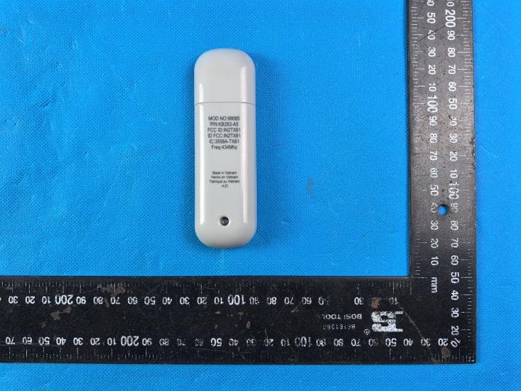
IN2TX61
Sep 11, 2024Remote Control for Ceiling Fan
Equipment Class
DSC - Part 15 Security/Remote Control Transmitter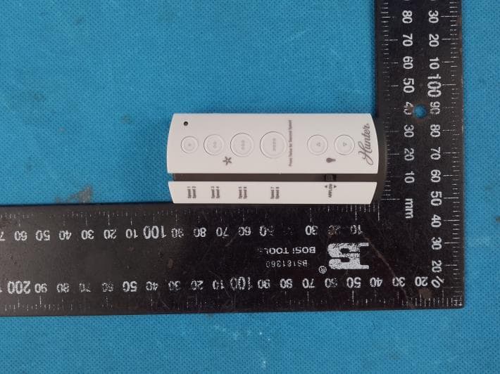
IN2TX57
Jul 03, 2023Remote Control for Ceiling Fan
Equipment Class
DSC - Part 15 Security/Remote Control Transmitter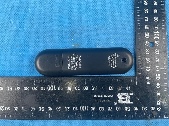
IN2TX52
Jan 10, 2023Remote Control for Ceiling Fan
Equipment Class
DSC - Part 15 Security/Remote Control Transmitter
IN2TX50
Jul 29, 2020Remote Control for Ceiling Fan
Equipment Class
DSC - Part 15 Security/Remote Control Transmitter
IN2TX49
Jun 14, 2020Remote control for ceiling fan
Equipment Class
DSC - Part 15 Security/Remote Control Transmitter