IN2TX20Remote Control Transmitter for Ceiling Fan
Hunter Fan Company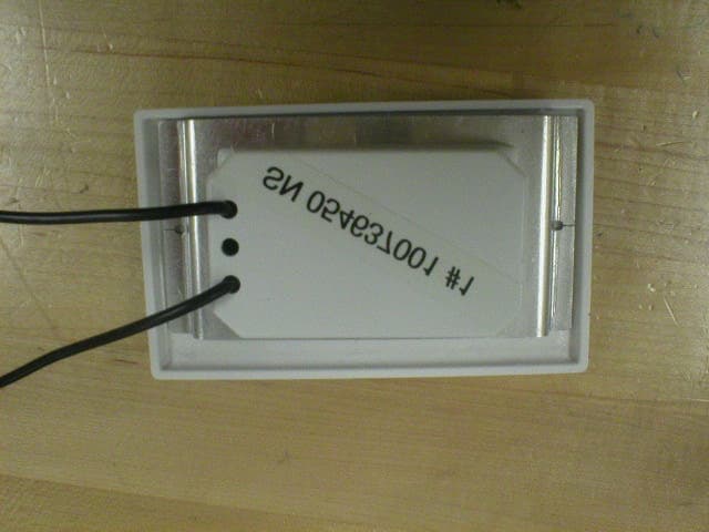
Click to zoom
Application Details
- Equipment Class
- DSC - Part 15 Security/Remote Control Transmitter
- Date of Grant
- Oct 12, 2004
- Application Purpose
- Original Equipment
- Date of Application
- Oct 12, 2004
- Equipment Note
- Remote Control Transmitter for Ceiling Fan
- Frequency Range
- 350.00000000 - 350.00000000
- Company
- Hunter Fan Company
- Country
- United States
Documents & Files
Document Text
Text extracted from the exhibit documents filed with the FCC. Open a document above to read the original.
Block Diagram
Hunter Fan & Light Remote Control Transmitter Block Diagram Antenna Loop Light1/Light2 Buttons Fan Low Button Fan Medium Button Fan High Button Fan Off Button Reverse Button U1 Encoder (HT-12E) Q2 (3356) ASK Modulator & Oscillator (350 MHz) Casablanca Fan & Light Remote Control RF Transmitter Coding Description: The Hunter transmitter uses the following code words to modulate on a 350 MHz RF carrier by using ASK modulation. Code words for the different commands: 1xxxx0000101 1xxxx0001001 1xxxx0000110 1xxxx0000111 1xxxx0001000 1xxxx0001101 1xxxx0001110 (Where “x” can be set to “1” or “0” by the user with DIP switches.) Code “0” is represented as: 0.42 ms 0.21ms Code “1” is represented as: 0.21ms 0.42ms The interval between two code words is about 7.56 ms.
External Photos
External Photo - Front Side Model 85773 (B21W) FCC ID: IN2TX20 External Photo - Reverse (Wall) Side Model 85773 (B21W) FCC ID: IN2TX20
ID Label/Location Info
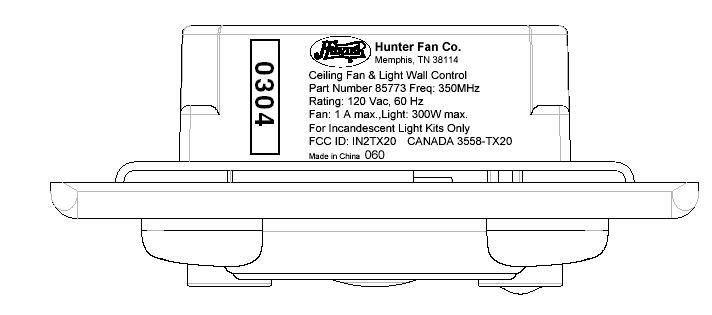
IN2TX20 Label Placement (Photo presents label placement on side of unit. Label contents are presented in the label exhibit).
Internal Photos
Internal Photo - Transmitter Board Component Side Model 85773 (B21W) FCC ID: IN2TX20 Internal Photo - Transmitter Board Solder Side Model 85773 (B21W) FCC ID: IN2TX20 Internal Photo - Main Board Component Side Model 85773 (B21W) FCC ID: IN2TX20 Internal Photo - Main Board Solder Side Model 85773 (B21W) FCC ID: IN2TX20
Operational Description
Hunter Fan & Light Remote Control Transmitter Operational Description Description: The top box of the diagram below represents all of the potential keys that may be pressed for the Hunter transmitter. Pressing any key generates an encoded PCM code word which will modulate on a 350 MHz RF carrier for transmission. The encoded PCM code word is obtained from encoder U1 and is ASK modulated by the RF oscillator formed by transistor Q2. Encoder U1 also provides four selectable security bits which can be set by the user. Antenna Loop Light1/Light2 Buttons Fan Low Button Fan Medium Button Fan High Button Fan Off Button Reverse Button U1 Encoder (HT-12E) Q2 (3356) ASK Modulator & Oscillator (350 MHz) Casablanca Fan & Light Remote Control RF Transmitter Coding Description: The Hunter transmitter uses the following code words to modulate on a 350 MHz RF carrier by using ASK modulation. Code words for the different commands: 1xxxx0000101 1xxxx0001001 1xxxx0000110 1xxxx0000111 1xxxx0001000 1xxxx0001101 1xxxx0001110 (Where “x” can be set to “1” or “0” by the user with DIP switches.) Code “0” is represented as: 0.42 ms 0.21ms Code “1” is represented as: 0.21ms 0.42ms The interval between two code words is about 7.56 ms.
Schematics
B21W-1(Fcc).sch-1 - Tue Feb 17 15:33:57 2004
Test Report
Project: 04RT02176 File: MC1324 Report: 040031 Date: February, 246, 2004 Model: 85773 (B21W) Test Report On Electromagnetic Compatibility Testing Hunter Fan Company Memphis, TN USA Copyright 2004 Underwriters Laboratories Inc. Underwriters Laboratories Inc. authorizes the above-named company to reproduce this Report provided it is reproduced in its entirety. Project: 04RT02176 Underwriters Laboratories, Inc. Issued: 2/24/04 File: MC1324 Test Report on Electromagnetic Compatibility Page 2 of 37 FCC ID: IN2TX20 Test Report: 040031 Test Report Details: Tests Performed By: Underwriters Laboratories Inc. 12 Laboratory Drive Research Triangle Park, NC 27709 Tests Performed For: Hunter Fan Company 2500 Frisco Avenue Memphis, TN 38114 USA Applicant Contact: Mr. Chris Williams Safety and Test Engineer (901) 248-2342 (901) 248-2382 - FAX Test Report Number: 040031 Test Report Date: February 24, 2004 Product Type: Remote Control for Ceiling Fan/Lamp Model Number: 85773 (B21W) Sample Serial Number: Unserialized, production sample Sample Tag Number: 0546317-001 EUT Category: Transmitter - Low Powered EUT Type: Wall Mounted Sample Receive Date: January 2, 2004 Testing Start Date: January 6, 2004 Date Testing Complete: January 21, 2004 Underwriters Laboratories Inc. reports apply only to the specific samples tested under stated test conditions. All samples tested were in good operating condition throughout the entire test program. It is the manufacturer's responsibility to assure that additional production units of this model are manufactured with identical electrical and mechanical components. Underwriters Laboratories Inc. shall have no liability for any deductions, inferences or generalizations drawn by the client or others from Underwriters Laboratories Inc. issued reports. This report shall not be used to claim, constitute or imply product certification, approval, or endorsement by NVLAP, A2LA, or any agency of the US government. This report may contain test results that are not covered by the NVLAP or A2LA accreditation. The scope of accreditation is limited to the specific tests that are listed on the NVLAP and/or A2LA certificates provided at the end of this report. Questions or comments regarding the test results presented within this report may be brought to the attention of the report author. Project: 04RT02176 Underwriters Laboratories, Inc. Issued: 2/24/04 File: MC1324 Test Report on Electromagnetic Compatibility Page 3 of 37 FCC ID: IN2TX20 Test Report: 040031 Summary of Testing: Test Test Name Comply Does Not See # Test Requirement/Specification Comply Remark 1 Radiated Disturbance Emissions - 30 MHz to 1000 MHz X - 47 CFR Part 15, Subpart C / 47 CFR Part 15, Subpart C, Section 15.209 and 15.231 2 Radiated Disturbance Emissions - Above 1 GHz X - 47 CFR Part 15, Subpart C / 47 CFR Part 15, Subpart C, Section 15.209 and 15.231 3 Radiated Disturbance Emissions - Peak-to-Average Ratio X - 47 CFR Part 15, Subpart C / 47 CFR Part 15, Subpart C, Section 15.231 4 Radiated Disturbance Emissions - Occupied Bandwidth X - 47 CFR Part 15, Subpart C / 47 CFR Part 15, Subpart C, Section 15.231 5 Radiated Disturbance Emissions - Restricted Bands X - 47 CFR Part 15, Subpart C / 47 CFR Part 15, Subpart C, Section 15.205 Remarks: 1) Device also complies with Canada RSS-210 requirements. All data was recorded on Industry Canada Registered Site IC-2953. Canadian Emissions designator L1D365K. 2) Device is exempt from routine RF exposure testing per FCC Part 2.1091. 3) Device contains an integrated antenna. It is not detachable or replaceable by the user. 4) All buttons cease transmission immediately upon release of button (i.e. less than 100 ms). This satisfies the 5 second maximum duration requirements of Part 15.231(a)(1). 5) The manufacturer made the following modification to comply: a. Capacitor C12 changed from 33pf to 22pf b. Resistor R3 changed from 75kΩ to 215 kΩ Conclusion: The tests listed in the Summary of Testing section of this report have been performed and the results recorded by Underwriters Laboratories Inc. in accordance with the procedures stated in each test requirement and specification. The test list was determined by the Applicant as being applicable to the Equipment Under Test. As a result, the subject product has been verified to comply or not comply as noted in the Summary of Testing with each test specification. The test results relate only to the items tested. Prepared By: Reviewed By: Ray Jones Jim Marley UL EMC Engineer NARTE Certified EMC Engineer (919) 549-1701 EMC-002278-NE (919) 549-1408 Project: 04RT02176 Underwriters Laboratories, Inc. Issued: 2/24/04 File: MC1324 Test Report on Electromagnetic Compatibility Page 4 of 37 FCC ID: IN2TX20 Test Report: 040031 Test Facilities: Test Location A) 10-Meter Anechoic Chamber (Industry Canada - IC 2953, NVLAP - 200246-0, VCCI - R-722) Constructed by Lindgren RF Enclosures, this room consists of a 17.9 by 12 by 8.3 m (inside clearance) shielded room lined with TDK absorber material. The walls, floor (conducting ground plane) and ceiling are constructed of double sided galvanized sheet steel supported by 19 mm thick particle board. The interior walls and ceiling are covered with 10 by 10 cm, 4.6 mm thick ferrite tiles and partially covered with polystyrene absorber cones. Removable floor tiles and cones covering the floor between the EUT and antenna are provided when RF immunity testing is performed. Room is provided with a 4.0 m diameter embedded turntable and a 1.2 by 2.1 m and 2.4 by 2.4 m double knife edge doors for access. Also, the room is fed electrical EUT power via permanently installed filters and is provided with a permanently mounted video surveillance camera. A remotely controllable antenna mast is located in the room for positioning the measuring antenna from 1 to 4 m above the ground plane. Test Location B) Compact Anechoic Chamber Constructed by Lindgren RF Enclosures, this room consists of a 6 by 3 by 2.9 m (inside cl…
Text truncated - open the document above for the full version.
Test Setup Photos
Project: 03RT10718 Underwriters Laboratories, Inc. Issued: 1/6/04 File: MC1324 Test Report on Electromagnetic Compatibility Page 15 of 37 Test Report: 040002 Test 1, All Items - Test Set-Up Photo: Radiated Disturbance Emissions - 30 MHz to 1000 MHz
Contact Information
Applicant
Julian A Martin(Compliance Manager)
Technical Contact
Hunter Fan CompanyRobert Davis
[email protected]901-248-2212
2500 Frisco Avenue · Memphis, Tennessee · United States
Non-Technical Contact
Hunter Fan CompanyRobert Davis
[email protected]901-248-2212
Test Firm
UL LLCRick Titus
Technical Specifications
| # | Rule Parts | Frequency Range | Power Output |
|---|---|---|---|
| 1 | 15.231 | 350 MHz - 350 MHz | - |
Other Applications from Hunter Fan Company
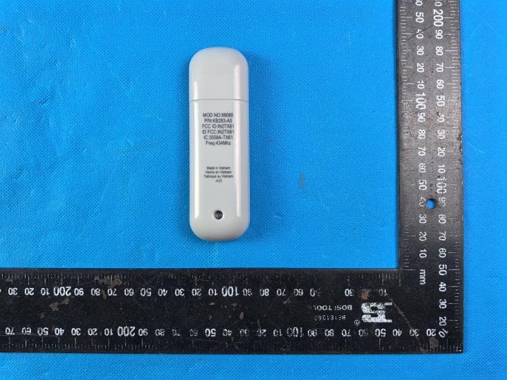
IN2TX61
Sep 11, 2024Remote Control for Ceiling Fan
Equipment Class
DSC - Part 15 Security/Remote Control Transmitter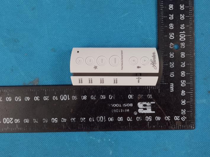
IN2TX57
Jul 03, 2023Remote Control for Ceiling Fan
Equipment Class
DSC - Part 15 Security/Remote Control Transmitter
IN2TX52
Jan 10, 2023Remote Control for Ceiling Fan
Equipment Class
DSC - Part 15 Security/Remote Control Transmitter
IN2TX50
Jul 29, 2020Remote Control for Ceiling Fan
Equipment Class
DSC - Part 15 Security/Remote Control Transmitter
IN2TX49
Jun 14, 2020Remote control for ceiling fan
Equipment Class
DSC - Part 15 Security/Remote Control Transmitter