IN2TX29Remote control for ceiling fan
Hunter Fan Company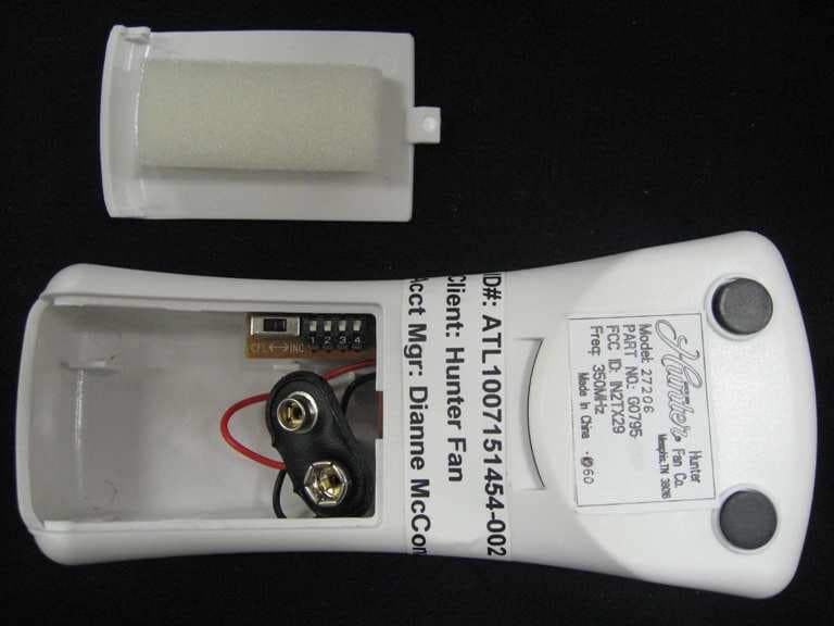
Click to zoom
Application Details
- Equipment Class
- DSC - Part 15 Security/Remote Control Transmitter
- Date of Grant
- Jul 29, 2010
- Application Purpose
- Original Equipment
- Date of Application
- Jul 29, 2010
- Equipment Note
- Remote control for ceiling fan
- Frequency Range
- 350.00000000 - 350.00000000
- Company
- Hunter Fan Company
- Country
- United States
Documents & Files
Document Text
Text extracted from the exhibit documents filed with the FCC. Open a document above to read the original.
Users Manual
Universal Fan and Light Remote Control Universal Fan and Light Remote Control Universal Fan and Light Remote Control Form# 41316-01 20100625 ©2010 Hunter Fan Co. English Owner’s Guide and Installation Manual Hand-Held Remote and Wall Cradle 2 41316-01 • 06/25/10 • Hunter Fan Company 1 • Welcome Table of Contents 1 • Welcome ..............................................................2 2 • Installation Preparation ...............................3 3 • DIP Switch Settings ........................................4 4 • Receiver Installation ......................................5 5 • Transmitter Installation ...............................8 6 • Operation ............................................................9 7 • Troubleshooting ...........................................10 8 • Warranty ...........................................................11 © 2010 Hunter Fan Company Read and Save these Instructions Caution: Risk of Electrical Shock! All wiring must be performed in accordance with national and local electrical codes. If you are unfamiliar with the wiring codes, you should use a qualified electrician. To avoid overheating and possible damage to other equipment, do not install to control a receptacle, fluorescent light fixture, motor operated appliance, or transformer-supplied appliance. Use only to control one ceiling fan with or without a light fixture. Ratings: 120 VAC, 60 Hz,1.0 Amp Fan Receiver Weight: 6 oz. 300 Watts incandescent light 3 41316-01 • 06/25/10 • Hunter Fan Company 2 • Installation Preparation Notes: 1. This device complies with Part 15 of the FCC Rules. Operation is subject to the following two conditions: (1) this device may not cause harmful interference, and (2) this device must accept any interference received, including interference that may cause undesired operation. 2. This equipment has been tested and found to comply with the limits for a Class B digital device, pursuant to Part 15 of the FCC Rules. These limits are designed to provide reasonable protection against harmful interference in a residential installation. This equipment generates, uses and can radiate radio frequency energy and, if not installed and used in accordance with the instructions, may cause harmful interference to radio communications. However, there is no guarantee that interference will not occur in a particular installation. If this equipment does cause harmful interference to radio or television reception, which can be determined by turning the equipment off and on, the user is encouraged to try to correct the interference by one or more of the following measures: • Reorient or relocate the receiving antenna. • Increase the separation between the equipment and receiver. • Connect the equipment into an outlet on a circuit different from the one the receiver is connected to. • Consult the dealer or an experienced radio/TV technician for help. 3. For use only with electrically reversible ceiling fans rated at 1.0 amp or less, and fan incandescent light kits rated at 300 watts or less. 4. Not for use with shaded-pole motors, Hunter 42” Low Profile fans, and Hunter Baseball fans. Not recommended for use with the Hunter Original®. For Hunter Original® series fans, use Hunter control model numbers 27187, 22691, or 27189. 5. Medium and Low fan speeds are determined by the control and thus may vary from the factory settings due to normal motor variations. 6. For use with Hunter Hanging Systems (excludes Hunter Original) on flat ceilings or angled ceilings with a pitch up to 34°. 7. Not for use in applications where the fan does not have a wall switch. Any changes or modifications to this equipment not expressly approved by Hunter Fan Company will void the user’s authority to operate the equipment. 4 41316-01 • 06/25/10 • Hunter Fan Company 3 • DIP Switch Settings BEFORE INSTALLING THE CONTROL: 1. Use the pull chain switch to set the fan speed to the HIGH position before installation. Do not use the pull chain to change the fan speed after installation, as damage to your ceiling fan or universal control may result. The speed of the fan should only be changed by the Hunter control. 2. Set the ceiling fan light kit to the ON position before installation. The light level should only be changed by the Hunter control. Installation Instructions: 1. Disconnect power to the ceiling fan and light kit at the main electrical panel. Remove fuse or move circuit breaker to the OFF position. 2. IMPORTANT! Before installing this control, check the factory default DIP switch settings. Refer to Figure 1. Be sure the DIP switch positions of the transmitters and receiver match, or the ceiling fan will not function. Select different combinations of dip switches to prevent mis-operation due to other remote control fans. 3. IMPORTANT! If your ceiling fan light kit is using incandescent bulbs, then slide the CFL / INC switch to the INC position. If your ceiling fan light kit is using compact fluorescent light bulbs (CFL), then slide the CFL / INC switch to the CFL position. NOTE: When the switch is in the CFL position, the dimming feature is disabled, and you will not be able to dim the light bulbs. This feature is to protect both your bulbs and your receiver as CFL bulbs are not able to dim and will malfunction if dimming is attempted. Dip Switches Set to 01110 Dip Switches Set to 01001 Dip Switches Set to 01110 Dip Switches Set to 01001 Receiver Transmitter Example DIP Switch Settings DIP Switches Set to 0111 DIP Switches Set to 0111 Figure 1 Transmitter DIP Switches CFL INC Figure 2 Receiver DIP Switches Figure 3 5 41316-01 • 06/25/10 • Hunter Fan Company 4 • Receiver Installation 4. Install the ceiling fan according to its instructions, up to the point of making the electrical connections. Connect receiver to ceiling fan according to the mounting types shown on the next page. Determine your ceiling fan mounting type from the images on Pages 5-6. Most installations will be one of these five types. 5. If the …
Text truncated - open the document above for the full version.
Block Diagram
25/Jun/200925/Jun/2010 Wy Qu Hoey Ng Computime.Ltd B 1 1 2 REV: SIZE: CODE: DRAWN: DATED: DATED: CHECKED:QUALITY CONTROL: DATED: DATED: RELEASED: COMPANY:TITLE: DRAWING NO: SHEET: OF SCALE: REVISION RECORD APPROVED: ECO NO: ABD DATE: 1 2 3 4 5 6 DCAB C LTR Key Input circuit Key Input circuitKey Input circuitKey Input circuit 1.2M 1.2M1.2M1.2M Encoder EncoderEncoderEncoder RF circuit RF circuitRF circuitRF circuit 303.5M 303.5M303.5M303.5M DC to DC DC to DCDC to DCDC to DC +3.3V DC +3.3V DC +3.3V DC +3.3V DC TX Block drawing of HUN3501 Dip SW for ID select Dip SW for ID selectDip SW for ID selectDip SW for ID select circuit circuitcircuitcircuit CFL switch CFL switchCFL switchCFL switch X3 2 1 9V BATT 25/Jun/2009 25/Jun/2010 Wy Qu Hoey Ng Computime.Ltd B 1 2 2 REV: SIZE: CODE: DRAWN: DATED: DATED: CHECKED:QUALITY CONTROL: DATED: DATED: RELEASED: COMPANY:TITLE: DRAWING NO: SHEET: OF SCALE: REVISION RECORD APPROVED: ECO NO: ABD DATE: 1 2 3 4 5 6 DCAB C LTR Live LiveLiveLive Neutral from wall control Neutral from wall controlNeutral from wall controlNeutral from wall control AC 120v AC 120v AC 120v AC 120v Voltage step down Voltage step down Voltage step down Voltage step down 8M Crystal 8M Crystal8M Crystal8M Crystal Microcontroller MicrocontrollerMicrocontrollerMicrocontroller REGULATOR REGULATORREGULATORREGULATOR +5V DC +5V DC+5V DC+5V DC 24V for Fan speed Relay 24V for Fan speed Relay24V for Fan speed Relay24V for Fan speed Relay Zero crossing detection circuit Zero crossing detection circuitZero crossing detection circuitZero crossing detection circuit S3F9488 S3F9488S3F9488S3F9488 Light Dimming control Light Dimming controlLight Dimming controlLight Dimming control Fan Speed control Fan Speed controlFan Speed controlFan Speed control RF Module RF ModuleRF ModuleRF Module RX main board of HUN3501 To Fan To FanTo FanTo Fan and Rectifier and Rectifierand Rectifierand Rectifier over-current protection over-current protectionover-current protectionover-current protection Current detection for Current detection forCurrent detection forCurrent detection for
Cover Letter(s)
Letter of Agency I appoint Intertek Testing Services NA Inc. to act on our behalf in front of the Federal Communications Commission with respect to all matters relating to certification of equipment under the FCC rules until further notice. I further certify that no party (as defined in 1.2002 of CFR 47, 1995) to this application, including myself, is subject to denial of federal benefits, that includes FCC benefits, pursuant to Section 5301 of the Anti-Drug Abuse Act of 1988, 21 U.S.C.,862. Equipment: Transmitter G0795 and Receiver GO797 Dated this 15 th day of July, 2010 Robert Davis Robert DavisRobert Davis Robert Davis Signature Robert Davis Name Manager of Compliance and Controls Title Hunter Fan Company Company 901-248-2212 Telephone
External Photos
Front Rear
ID Label/Location Info
Front Rear
Operational Description
HUN3501 RF module Circuit Description Transmitter 1. Power Supply: Used the 9V battery for encoder and an electronic circuit capable stepping down the voltage to +3.3VDC to Transmitter RF module. 2. Function: The HUN3501 to control the FAN speed and Light dimming function through 350MHz RF signal. 3. Harmonic Filter: The harmonic filter is build of C2, C6, C11, C3, L4 and L7 in order to reduce the harmonic signal to meet FCC regulation. 4. ID SW setting: The 4 Switch DIP to setting the address cord for the usage of multiple Receivers. 5. CFL select: The toggle switch to setting the CFL and INC. 6. Antenna: A 350MHz PCB routing antenna is used to transmit carrier RF signal.
Schematics
C BACD 6 5 4 3 2 1 DATE: DBA REVISION RECORD RF BOARD COMPANY: REV: SIZE: FILE NAME TITLE: RELEASED: DATED: DATED: CHECKED: DATED: DATED: DRAWN: SHEET: OF SCALE: A4 CB CAI MAY.18. 2010 COMPUTIME HUN3501 350MHz TX Module APPROVED: PCB FILE NAME: HUN3501_TX_Module_Rev2 5 REV1.0 2009.06.26 FIRST RELEASE REV2.0 * * * * * Hunter 27185 Fan And Light Remote Control J1 Remark: Item Rev2 Rev3 L9 100nH shot C14 1000P not use Rev4 C10 100P 10P Rev5 0 ohm R8 22K 47K R9 120 C1 1000P C2 5P C3 200P R4 0 L1 39nH C5 10NF C6 10P C8 4.7P C9 1P R6 330 SAW2 350MHz C100 C11 200p L7 100nH L8 39nH C12 3300P C13 20p R8 47K R12 22K Q3 MMBTH10LT1 Q62SC3838Q R13 56 L9 shot 1 TX-DATA 2 VDD 3 GND 4 ANT-OUT L2 NOT USE C14not use
Test Report
Client: Product Designation: Remote Control Model G0795 Report Number: 100169885ATL-001 All services undertaken are subject to the following general policy: This report is for the exclusive use of Intertek's Client and is provided pursuant to the agreement between Intertek and its Client. Intertek's responsibility and liability are limited to the terms and conditions of the agreement. Intertek assumes no liability to any party, other than to the Client in accordance with the agreement, for any loss, expense or damage occasioned by the use of this report. Only the Client is authorized to copy or distribute this report and then only in its entirety. Any use of the Intertek name or one of its marks for the sale or advertisement of the tested material, product or service must first be approved in writing by Intertek. The observations and test results in this report are relevant only to the sample tested. This report by itself does not imply that the material, product, or service is or has ever been under an Intertek certification program. This report must not be used to claim product endorsement by A2LA, NIST, or any agency of the US Government. Tested by: Tests performed by:Report reviewed by: Standard: Richard C. Bianco EMC Project Engineer Jeremy O. Pickens EMC Department Manager Hunter Fan 7130 Goodlett Farms Pkwy Suite 400 Memphis, TN 38016 Contact: Robert Davis Phone: 901.248.2212 TEST REPORT July 28, 2010 Intertek Testing Services NA Inc. 1950 Evergreen Blvd., Suite 100 Duluth, GA 30096 47 CFR Part 15, Subpart C (15.231 - Periodic operation in the band 40.66- 40.70 MHz and above 70 MHz) RSS-210, Issue 7, 2007 Page 1 of 22EMC Report for Hunter Fan on the Remote Control Model G0795 07/28/2010Report Number: 100169885ATL-001Issued: Intertek 2.0 Test Summary 1.0 Introduction and Conclusion Test DateTest Full NameResultSection System setup including cable interconnection details, support equipment and simplified block diagram. (System Setup)4.0 Overview of EUT (Low Power Transmitters) (FCC 15C - EUT Overview)5.0 07/15/2010Restrictions (FCC 15C - 15.231(a))PASS6.0 07/15/2010Duty Cycle Determination (FCC 15A - 15.35(c))PASS7.0 07/16/2010Radiated Emissions (FCC 15C - 15.231(b))PASS8.0 07/16/2010Bandwidth Requirements (FCC 15C - 15.231(c))PASS9.0 Conducted emissions on AC power lines (Conducted Emissions) was waived due to the EUT does not connect to the AC mains. NA Conducted Emissions for Intentional Radiators (FCC 15C - 15.207) was waived due to the EUT does not connect to the AC mains. NA The tests indicated in section 2.0 were performed on the product constructed as described in section 3.0. The remaining test sections are the verbatum text from the actual data sheets used during the investigation. These test sections include the test name, the specified test Method, a list of the actual Test Equipment Used, documentation Photos, Results and raw Data. No additions, deviations, or exclusions have been made from the standard(s) unless specifically noted. Based on the results of our investigation, we have concluded the product tested complies with the requirements of the standard(s) indicated. The results obtained in this test report pertain only to the item(s) tested. Page 2 of 22EMC Report for Hunter Fan on the Remote Control Model G0795 07/28/2010Report Number: 100169885ATL-001Issued: Intertek 3.0 Description of Equipment Under Test Eq uip me nt Unde r T est Description Manu fac ture r Mo del N umbe r Serial Nu mb er Fan/Light remote control Hunter Fan G0795 3 EUT receive date: 07/15/2010 EUT receive condition: Good Description of EUT provided by Client: The G0795 is a remote control for a lighted ceiling fan. Description of EUT exercising: The remote control was powered with a new battery and placed in a rapid transmit mode with normal modulation. Page 3 of 22EMC Report for Hunter Fan on the Remote Control Model G0795 07/28/2010Report Number: 100169885ATL-001Issued: Intertek System setup including cable interconnection details, support equipment and simplified block diagram. (System Setup) 4.0 Method: Record the details of EUTcabling, document the support equipment, and show the interconnections in a block diagram. EUT Simplified Block Diagram Drawing: Page 4 of 22EMC Report for Hunter Fan on the Remote Control Model G0795 07/28/2010Report Number: 100169885ATL-001Issued: Intertek System setup including cable interconnection details, support equipment and simplified block diagram. (System Setup) 4.0 Description EUT Cabling Connection Length Shielding FerritesIDFromTo No cabling required Support Equipment DescriptionManufacturerModel NumberSerial Number No support equipment required Data: Page 5 of 22EMC Report for Hunter Fan on the Remote Control Model G0795 07/28/2010Report Number: 100169885ATL-001Issued: Intertek Overview of EUT (Low Power Transmitters) (FCC 15C - EUT Overview)5.0 Method: Complete the overview spreadsheet. Related Submittal(s) Grants: This report is for use with an application for certification of a low power transmitter. One transmitter is included in the application. Hunter Fan 7130 Go o d lett Farms Pkwy Ste. 400 M emph is TN 38016 Trade Name & Model No. G0795 FCC Identifier IN2TX29 Frequency Range (MHz) 350 A nten na Typ e (15.203) In ternal Hunter Fan 7130 Go o d lett Farms Pkwy Ste. 400 M emph is TN 38016 Additions, deviations and exclusions from standards None This report is for use with an application for certification of a low power transmitter. One transmitter is included in the application. Applicant Manufacturer name & address Related Submittals and Grants: Data: Page 6 of 22EMC Report for Hunter Fan on the Remote Control Model G0795 07/28/2010Report Number: 100169885ATL-001Issued: Intertek Restrictions (FCC 15C - 15.231(a))6.0 Method: 15.231(a) The provisions of this section are restricted to periodic operation within the band 40.66-40.70 MHz and above 70 MHz. Except as shown in paragraph (e) of this section, the intentional radiator is restricted to the tra…
Text truncated - open the document above for the full version.
Test Setup Photos
07/28/2010Report Number: 100169885ATL-001Issued: Intertek Radiated Emissions (FCC 15C - 15.231(b))8.0 Test Setup - Front view Photo: Page 14 of 22 EMC Report for Hunter Fan on the Remote Control Model G0795 07/28/2010Report Number: 100169885ATL-001Issued: Intertek Radiated Emissions (FCC 15C - 15.231(b))8.0 Test Setup - Rear view Photo: Page 15 of 22 EMC Report for Hunter Fan on the Remote Control Model G0795
Contact Information
Applicant
Julian A Martin(Compliance Manager)
Test Firm
Intertek Testing Services NA Inc.Charles Parker
Technical Specifications
| # | Rule Parts | Frequency Range | Power Output |
|---|---|---|---|
| 1 | 15.231 | 350 MHz - 350 MHz | - |
Other Applications from Hunter Fan Company
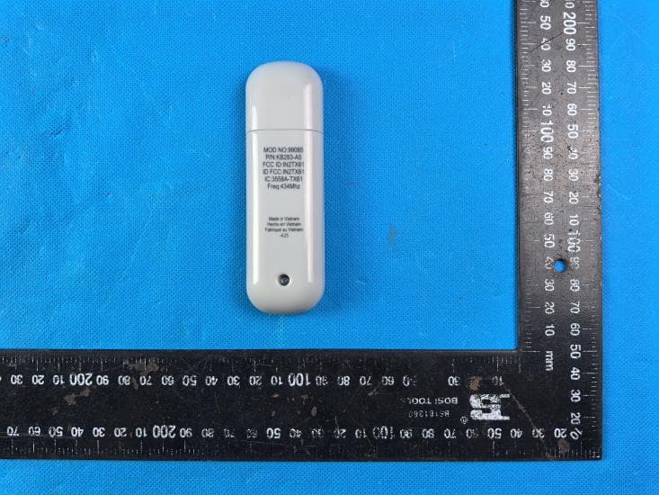
IN2TX61
Sep 11, 2024Remote Control for Ceiling Fan
Equipment Class
DSC - Part 15 Security/Remote Control Transmitter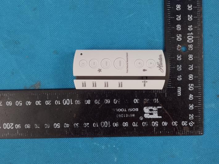
IN2TX57
Jul 03, 2023Remote Control for Ceiling Fan
Equipment Class
DSC - Part 15 Security/Remote Control Transmitter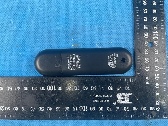
IN2TX52
Jan 10, 2023Remote Control for Ceiling Fan
Equipment Class
DSC - Part 15 Security/Remote Control Transmitter
IN2TX50
Jul 29, 2020Remote Control for Ceiling Fan
Equipment Class
DSC - Part 15 Security/Remote Control Transmitter
IN2TX49
Jun 14, 2020Remote control for ceiling fan
Equipment Class
DSC - Part 15 Security/Remote Control Transmitter