IN2TX31Wall Fan Control
Hunter Fan Company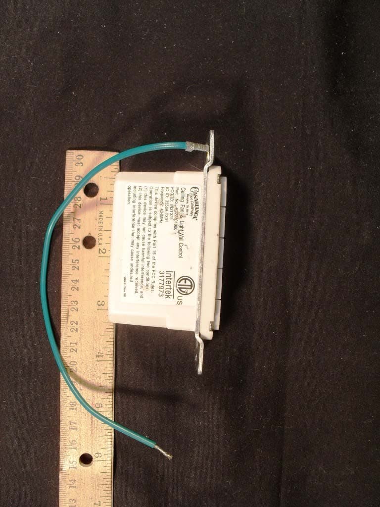
Click to zoom
Application Details
- Equipment Class
- DSC - Part 15 Security/Remote Control Transmitter
- Date of Grant
- Aug 08, 2012
- Application Purpose
- Original Equipment
- Date of Application
- Aug 08, 2012
- Equipment Note
- Wall Fan Control
- Frequency Range
- 434.00000000 - 434.00000000
- Company
- Hunter Fan Company
- Country
- United States
Documents & Files
Document Text
Text extracted from the exhibit documents filed with the FCC. Open a document above to read the original.
Users Manual
www.CasablancaFanCo.com 1.888.227.2178 11 M6003-01 • 05/22/12 • © Casablanca Fan Company Using orange wire connectors, connect the two black wires (ungrounded) from the outlet box. Also connect the two green or bare wires (grounding) from the outlet box with the grounding wire from the wall control. After removing the switch plate cover, remove all wiring from the switch. Insert the wall control into the outlet box and secure the two screws using a Phillips head screwdriver. Install the cover plate using a Phillips Head screwdriver to secure the two cover plate screws. Wiring (continued) Push all connections to the back of the switch box. Spread the wires apart, with the grounded wires on one side of the outlet box and the ungrounded wires on the other side of the outlet box. This device complies with Part 15 of the FCC Rules. Operation is subject to the following conditions: (1) this device may not cause harmful interference, and (2) this device must accept any interference received, including interference that may cause undesired operation. Before BeforeBefore Before AfterAfterAfterAfter
Block Diagram
3 volt battery Regulator Key Input Circuit Led controller 433Mhz BLOCK DIAGRAM INTX31
Cover Letter(s)
Letter of Agency I appoint Intertek Testing Services NA Inc. to act on our behalf in front of the Federal Communications Commission with respect to all matters relating to certification of equipment under the FCC rules until further notice. I further certify that no party (as defined in 1.2002 of CFR 47, 1995) to this application, including myself, is subject to denial of federal benefits, that includes FCC benefits, pursuant to Section 5301 of the Anti-Drug Abuse Act of 1988, 21 U.S.C.,862. Equipment: Transmitter (IN2TX31) Dated this 28 th day of July, 2012 Robert Davis Robert DavisRobert Davis Robert Davis Robert Davis Manager of Compliance and Controls Hunter Fan Company 901-248-2212
Operational Description
www.CasablancaFanCo.com 1.888.227.2178 M6003-01 • 05/22/12 • © Casablanca Fan Company 17 Operation Before operating the wall control, open the battery holder by pressing in on the battery holder. Remove the protective film from the battery. Replace the battery holder. Quickly press the up or down arrow to turn the lights off and on. Hold the up or down arrow to dim or raise the light level. The reverse button changes the direction that the blades turn. The power button turns the fan off and on. The fan must be paired before it will operate. Press the “4” button and the fan power button simultaneously for at least three seconds. The fan will turn at the lowest speed signifying that the remote pairing process is complete. ON Turn Power Lights Down Fan Speed Reverse Battery Holder Fan Power Lights Up Fan Speed Fan Power 4 Battery Battery Holder (Low) (High) Once the power is turned on, the remote must be paired within three minutes. Pairing is only required once after initial installation. Industry Canada: Operation is subject to the following two conditions: (1) this device may not cause interference, and (2) this device must accept any interference, including interference that may cause undesired operation of the device.
Test Report
Client: Product Designation: K0233 Transmitter Wall Control Report Number: 100766024ATL-005 All services undertaken are subject to the following general policy: This report is for the exclusive use of Intertek's Client and is provided pursuant to the agreement between Intertek and its Client. Intertek's responsibility and liability are limited to the terms and conditions of the agreement. Intertek assumes no liability to any party, other than to the Client in accordance with the agreement, for any loss, expense or damage occasioned by the use of this report. Only the Client is authorized to copy or distribute this report and then only in its entirety. Any use of the Intertek name or one of its marks for the sale or advertisement of the tested material, product or service must first be approved in writing by Intertek. The observations and test results in this report are relevant only to the sample tested. This report by itself does not imply that the material, product, or service is or has ever been under an Intertek certification program. This report must not be used to claim product endorsement by A2LA, NIST, or any agency of the US Government. Tested by: Tests performed by:Report reviewed by: Standard: Yuneush Khan EMC Associate Engineer Jeremy O. Pickens Senior Staff Engineer Hunter Fan 7130 Goodlett Farms Parkway, Ste 400 Memphis, TN 38016 Contact: Robert Davis Phone: 901-248-2212 Fax: 901-248-2382 [email protected] TEST REPORT June 29, 2012 Intertek Testing Services NA Inc. 1950 Evergreen Blvd., Suite 100 Duluth, GA 30096 47 CFR Part 15, Subpart C (15.231 - Periodic operation in the band 40.66- 40.70 MHz and above 70 MHz) RSS-210, Issue 8, 2010 Page 1 of 32EMC Report for Hunter Fan on the K0233 Transmitter Wall Control 06/29/2012Report Number: 100766024ATL-005Issued: Intertek 2.0 Test Summary 1.0 Introduction and Conclusion Test DateTest Full NameResultSection System setup including cable interconnection details, support equipment and simplified block diagram. (System Setup)4.0 Overview of EUT (Low Power Transmitters) (FCC 15C - EUT Overview)5.0 06/29/2012Restrictions (FCC 15C - 15.231(a))PASS6.0 06/26/2012Duty Cycle Determination (FCC 15A - 15.35(c))PASS7.0 06/04/2012Radiated Emissions (FCC 15C - 15.231(b))PASS8.0 06/29/2012Bandwidth Requirements (FCC 15C - 15.231(c))PASS9.0 Conducted emissions on AC power lines (Conducted Emissions) was waived due to the device was powered with an internal battery. NA The tests indicated in section 2.0 were performed on the product constructed as described in section 3.0. The remaining test sections are the verbatum text from the actual data sheets used during the investigation. These test sections include the test name, the specified test Method, a list of the actual Test Equipment Used, documentation Photos, Results and raw Data. No additions, deviations, or exclusions have been made from the standard(s) unless specifically noted. Based on the results of our investigation, we have concluded the product tested complies with the requirements of the standard(s) indicated. The results obtained in this test report pertain only to the item(s) tested. Page 2 of 32EMC Report for Hunter Fan on the K0233 Transmitter Wall Control 06/29/2012Report Number: 100766024ATL-005Issued: Intertek 3.0 Description of Equipment Under Test Equipment Under Test Description Manufacturer Model Number Serial Number Transmitter Wall Control Hunter Fan K022301000 N/A EUT receive date: 05/31/2012 EUT receive condition: Good Description of EUT provided by Client: The EUT was a wall mount wireless transmitter used for remote control of a ceiling fan and light assembly.. Description of EUT exercising: During testing, the device was powered from a new internal CR2032 battery and configured to transmit continuously. Page 3 of 32EMC Report for Hunter Fan on the K0233 Transmitter Wall Control 06/29/2012Report Number: 100766024ATL-005Issued: Intertek System setup including cable interconnection details, support equipment and simplified block diagram. (System Setup) 4.0 Method: Record the details of EUTcabling, document the support equipment, and show the interconnections in a block diagram. 1 2 3 4< > Block Diagram Drawing: Page 4 of 32EMC Report for Hunter Fan on the K0233 Transmitter Wall Control 06/29/2012Report Number: 100766024ATL-005Issued: Intertek System setup including cable interconnection details, support equipment and simplified block diagram. (System Setup) 4.0 None Support Equipment DescriptionManufacturerModel NumberSerial Number None Description EUT Cabling Connection Length Shielding FerritesIDFromTo Data: Page 5 of 32EMC Report for Hunter Fan on the K0233 Transmitter Wall Control 06/29/2012Report Number: 100766024ATL-005Issued: Intertek Overview of EUT (Low Power Transmitters) (FCC 15C - EUT Overview)5.0 Method: Complete the overview spreadsheet. Related Submittal(s) Grants: This report is for use with an application for certification of a low power transmitter. One transmitter is included in the application. Page 6 of 32 EMC Report for Hunter Fan on the K0233 Transmitter Wall Control 06/29/2012Report Number: 100766024ATL-005Issued: Intertek Overview of EUT (Low Power Transmitters) (FCC 15C - EUT Overview)5.0 Hunter Fan Company 7130 Goodlett Parkway, Suite 400 M emp h is , TN 38016 Trade Name & Model No. K0233 FCC Identifier IN2TX31 Frequency Range (MHz) 433.9 Antenna Type (15.203) Integral Manufacturer name & address Ansen Electronics Company Chen Tung Industrial Zone Ning Tau Administrative District Qiao Tau Zhen DONGGUA N Additions, deviations and exclusions from standards None This report is for use with an application for certification of a low power transmitter. One transmitter is included in the application. Applicant Related Submittals and Grants: Data: Page 7 of 32EMC Report for Hunter Fan on the K0233 Transmitter Wall Control 06/29/2012Report Number: 100766024ATL-005Issued: Intertek Restrictions (FCC 15C - 15.231(a))6.0 Method: 15.231(a) The provisions o…
Text truncated - open the document above for the full version.
Contact Information
Applicant
Julian A Martin(Compliance Manager)
Test Firm
Intertek Testing Services NA Inc.Charles Parker
Technical Specifications
| # | Rule Parts | Frequency Range | Power Output |
|---|---|---|---|
| 1 | 15.231 | 434 MHz - 434 MHz | - |
Other Applications from Hunter Fan Company
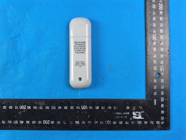
IN2TX61
Sep 11, 2024Remote Control for Ceiling Fan
Equipment Class
DSC - Part 15 Security/Remote Control Transmitter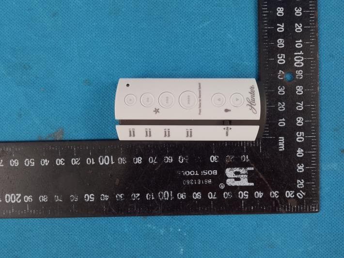
IN2TX57
Jul 03, 2023Remote Control for Ceiling Fan
Equipment Class
DSC - Part 15 Security/Remote Control Transmitter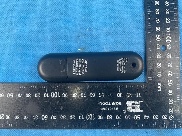
IN2TX52
Jan 10, 2023Remote Control for Ceiling Fan
Equipment Class
DSC - Part 15 Security/Remote Control Transmitter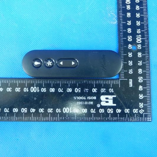
IN2TX50
Jul 29, 2020Remote Control for Ceiling Fan
Equipment Class
DSC - Part 15 Security/Remote Control Transmitter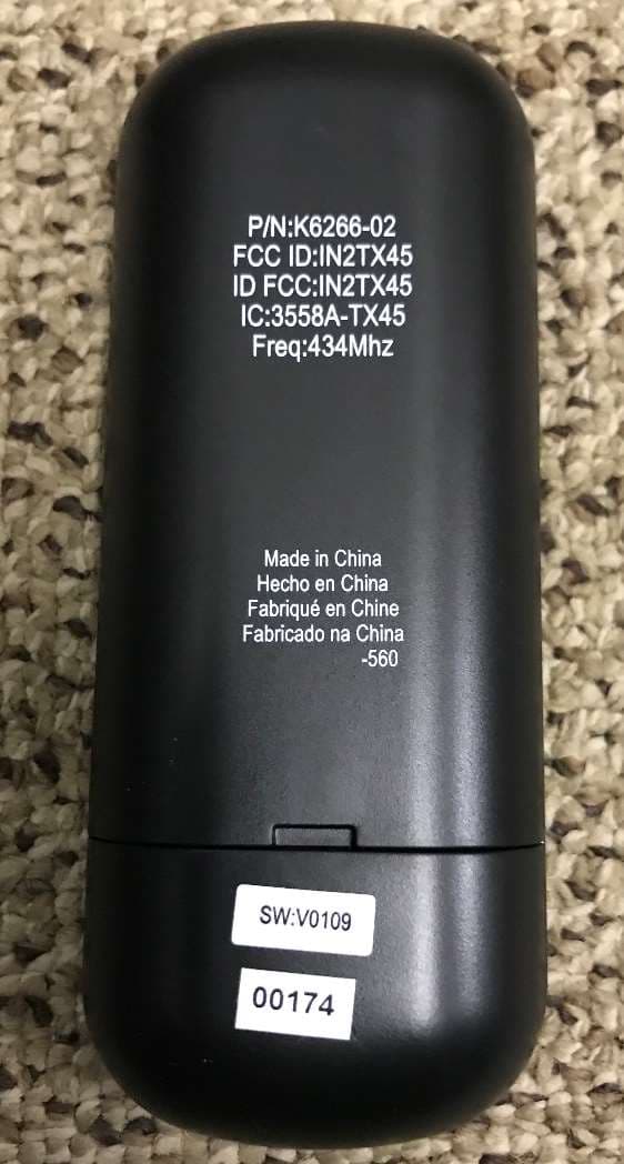
IN2TX49
Jun 14, 2020Remote control for ceiling fan
Equipment Class
DSC - Part 15 Security/Remote Control Transmitter