IN2TX35Fan Remote Control
Hunter Fan Company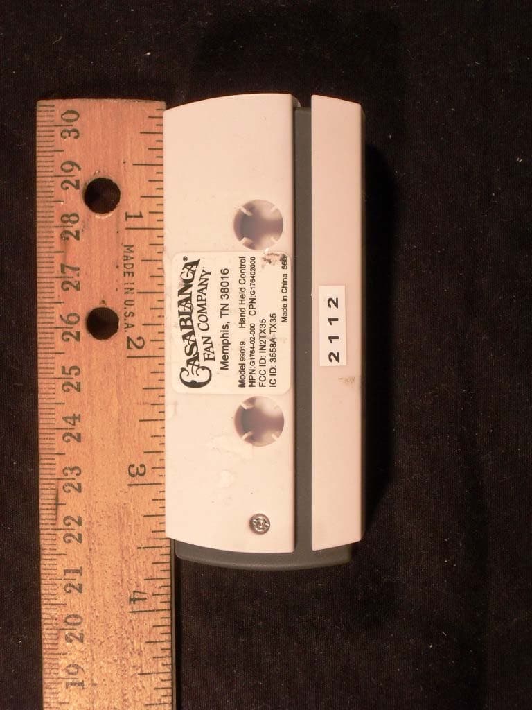
Click to zoom
Application Details
- Equipment Class
- DSC - Part 15 Security/Remote Control Transmitter
- Date of Grant
- Sep 05, 2012
- Application Purpose
- Original Equipment
- Date of Application
- Sep 05, 2012
- Equipment Note
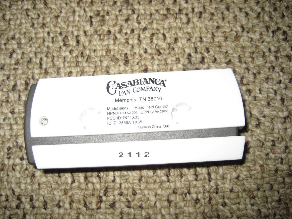
- Fan Remote Control
- Frequency Range
- 434.00000000 - 434.00000000
- Company
- Hunter Fan Company
- Country
- United States
Documents & Files
Document Text
Text extracted from the exhibit documents filed with the FCC. Open a document above to read the original.
Users Manual
Hunter Fan Company Confidential Confidential FUNCTIONAL SPECIFICATION Remote Fan & Light Control Page 1 65535 65536 Receiver Hunter Fan Company Confidential 2 Hunter Fan Company Confidential 3 I. General Description Transmitter Receiver Feature Housing color Battery Feature Terminal 7 buttons (fan speed OFF, 1, 2, 3, 4, light Up, Down button). Blue LED x 1. TBD 5 wires interface (L, N, Fan output, DownLight output, Common) 7 buttons (fan speed OFF, 1, 2, 3, 4, light Up, Down button) + 1 slide switch for Reverse. Blue LED x 1. TBD 6 wires interface (L, N, Fan output, DownLight output, Uplight output, Common) 9 buttons (fan speed OFF, 1, 2, 3, 4, Reverse, light Up, Down, Power button). TBD DC 3V CR2032battery 120V/60Hz Learning code, Fan speed 1,2,3, off. Light on, off, dimming. SCP, Safe Exit, Light type auto- detection, 190w limiter (optional). 3 wires interface (Live in, Live out, Ground) Hu Hunter Fan Company Confidential 4 III. Functional Specifications Receiver : • 1. Fan Control – A Total of 4 Speed Buttons and one OFF button on side shall be used to initiate Fan Control functions. a) OFF Function: A Press/Release of the “Fan OFF” button on side shall turn the fan OFF. b) Four Speed Motor Control: 1, 2, 3 & 4 represents fan speed from low to high. 2. L i g h t i n g C o n t r o l – I n o r d e r t o r e d u c e c o m p l e x i t y i n manufacturing and standardize to one version of firmware, an up- light detection routine is included in firmware that is run each time the power is cycled to the receiver. A very brief flash will be seen on the up-light during this time. If there IS an up-light detected then: a) the button on the transmitter with the up arrow will serve as the dimmer and the ON/OFF button for the up-light. A momentary press will change the state of the up-light. A press and hold will begin to increase lumen output of the up-light. A release followed by another press and hold will continue to increase lumen output of the up-light up to 100%. Continuing to hold the button with the up arrow will cause the lumen output to jump from 100% to 10% and continue increasing. Full one way cycle will last 8 seconds. b) the button on the transmitter with the down arrow will serve as the dimmer and the ON/OFF button for the down- light. A momentary press will change the state of the down-light. A press and hold will begin to decrease lumen output of the down-light. A release followed by another press and hold will decrease lumen output of the down-light to 10%. Continuing to hold the button with the down arrow will cause the lumen output of the down-light to jump from 10% to 100% and then back down. Full one way cycle will last 8 seconds. c) If there is NOT an up-light detected then a momentary Hunter Fan Company Confidential 5 push of either light button will change the state of the down- light. A press and hold of either light button will increase or decrease lumen level as described above 3. Transmit LED Indicator – A small blue LED shall be used to visually display Fan, Lighting Control, Safe Exit and Learning Mode commands initiated by pressing the appropriate buttons. 4. CFL and Incandescent Control Mode – The unit shall automatically detect for the presence of CFL or incandescent bulbs. Once the presence of CFL bulbs is established, the dimming functions will be disabled and the Down-light buttons will turn the lights on and off only. 5. Electrical Disturbance Feature – The lights and fan shall power up in the state they were in before the Power On Reset including lighting level and fan speed. 6. Learning Mode - This feature shall be initiated by cycling the power to the fan. For 3 minutes after cycling power to the fan the pairing operation can be implemented on the handheld remote whereby pressing both HIGH & OFF (4 & 0) Fan Speed Buttons for at least 3 seconds shall send an encoded binary bit message to a target receiver-controller. The Transmit LED Indicator shall flash 3 times and the fan shall turn at the lowest speed signifying the Learning Process is completed. The lights shall not change state during this operation. 7. Safe Exit Mode– This feature shall allow egress from a room with a time delay –OFF light source. To initiate the Safe Exit feature, the following steps shall be embedded within the handheld remote and receiver-controllers microcontrollers’ memory. The Safe Exit Mode operation shall be explained for Hunter Fan Company Confidential 6 both Incandescent and CFL based bulbs. This shall not affect fan operation. a) Incandescent Lighting: Press of the fan OFF Button on the handheld remote for at least 3 seconds shall initiate the Safe Exit Mode. (1) The Ceiling Fan Down-lights and the LED on the handheld remote shall flash 2 times for visual confirmation. (2) The down-lights shall stay ON 50% brightness for 20 seconds and then begin to dim. After a total of 30 seconds has elapsed, the down-lights shall be OFF completely. (3) To cancel the Safe-Exit program while it is running, either Down-light Control Button shall be pressed for 3 seconds. b) CFL Lighting (1) Press of the fan OFF button on the handheld remote for at least 3 seconds shall initiate the Safe Exit Mode. The Ceiling Fan Down-lights and the LED on the handheld remote shall flash 2 times for visual confirmation (2) The Down-lights shall stay ON 100% brightness for 30 seconds. After 30 seconds has elapsed, the down-lights shall be completely OFF. (3) To cancel the Safe-Exit program while it is running, either Down-light Control Button shall be pressed for 3 seconds. Hunter Fan Company Confidential 7 B. TRANSMITTER 1. Fan Control – A Total of 4 Speed Buttons and one OFF button on side shall be used to initiate Fan Control functions. a) OFF Function: A Press/Release of the “Fan OFF” button on side shall turn the fan OFF. b) Four Speed Motor Control: 1, 2, 3 & 4 represents fan speed from low to high. 2. Lighting Control – In order to reduce complexity in manufacturing and standardize to one version of f…
Text truncated - open the document above for the full version.
Attestation Statements
Letter of Agency I appoint Intertek Testing Services NA Inc. to act on our behalf in front of the Federal Communications Commission with respect to all matters relating to certification of equipment under the FCC rules until further notice. I further certify that no party (as defined in 1.2002 of CFR 47, 1995) to this application, including myself, is subject to denial of federal benefits, that includes FCC benefits, pursuant to Section 5301 of the Anti-Drug Abuse Act of 1988, 21 U.S.C.,862. Equipment: 99019 (IN2TX35) Dated this 28 th day of May, 2012 Robert Davis Robert DavisRobert Davis Robert Davis Signature Robert Davis Name Manager of Compliance and Controls Title Hunter Fan Company Company 901-248-2212 Telephone
Block Diagram
3 volt battery Regulator Key Input Circuit Led controller 433Mhz BLOCK DIAGRAM INTX31
Operational Description
TX35 RF Circuit Description Transmitter 1. Power Supply: Used the 9V battery for encoder and an electronic circuit capable stepping down the voltage to +3.3VDC to Transmitter RF module. 2. Function: The TX35 to control the FAN speed and Light dimming function through 434MHz RF signal. 3. Harmonic Filter: The harmonic filter is build of C2, C6, C11, C3, L4 and L7 in order to reduce the harmonic signal to meet FCC regulation. 4. ID SW setting: The 4 Switch DIP to setting the address cord for the usage of multiple Receivers. 5. CFL select: The toggle switch to setting the CFL and INC. 6. Antenna: A 434MHz PCB routing antenna is used to transmit carrier RF signal.
Schematics
1 1 2 2 3 3 4 4 DD CC BB AA Title NumberRevisionSize Letter Date:5/31/2012Sheet of File:C:\Users\..\Remote_65537_V2p3.SchDocDrawn By: 10nH C1 GND +3v GND DNI L1 +3V GND +3v GND GND GND GND Speed0 100nF 445-1324-1-ND C7 Cap 0603 GND 100nF 445-1324-1-ND C5 Cap 0603 100pf 445-1281-1-ND C2 Cap 0603 100nF 445-1324-1-ND C3 Cap 0603 DNI C6 DNI Speed1 Speed2 Speed3 Speed4 Light_On Light_Off Reverse Speed0 Speed1 Speed2Speed3 Speed4 Light_On Light_Off Reverse Hunter Remote 65537 3V CR2032 Ichiro Aoki Ver 2p3 AyDeeKay LLC +1.8V SWCLK SWDIO P9 1 P8 2 P7 3 P6 4 P5 5 GND 0 TMS 6 SWCLK 7 SWDIO 8 V1V8 9 VBAT 10 P2 11 P1 12 P0 13 RFOUT 14 VQP 15 C2 16 C1 17 P11 18 P10 19 XTAL 20 U1 HeimdallS Rf VQP IT-1157 IL Switch FAN_OFF smd_4pin_ 5.2mm x 6.3mm - HUNTER IT-1157 IL Switch FAN_HI smd_4pin_ 5.2mm x 6.3mm - HUNTER IT-1157 IL Switch LIGHT_ON smd_4pin_ 5.2mm x 6.3mm - HUNTER LightToggle LightToggle IT-1157 IL Switch FAN_MED smd_4pin_ 5.2mm x 6.3mm - HUNTER IT-1157 IL Switch FAN_LOW smd_4pin_ 5.2mm x 6.3mm - HUNTER IT-1157 IL Switch FAN_MED_HI smd_4pin_ 5.2mm x 6.3mm - HUNTER IT-1157 IL Switch LIGHT_OFF smd_4pin_ 5.2mm x 6.3mm - HUNTER IT-1157 IL Switch REVERSE smd_4pin_ 5.2mm x 6.3mm - HUNTER 887-1032-ND Y1 30MHz crystal Antenna 33nH C4 0 Ohm C8 GND 100pF L4 33nH L3 0 Ohm C10 GND 3.9pF L2 Y1 C11 DNI 100pf 445-1281-1-ND C12 Cap 0603 GND GND 100pf 445-1281-1-ND C13 Cap 0603 Place C13 on Vdd Line feeding Fan OFF PIAntenna01 COAntenna PIC101 PIC102 COC1 PIC201 PIC202 COC2 PIC301 PIC302 COC3 PIC401PIC402 COC4 PIC501 PIC502 COC5 PIC601PIC602 COC6 PIC701 PIC702 COC7 PIC801 PIC802 COC8 PIC1001 PIC1002 COC10 PIC1101 PIC1102 COC11 PIC1201 PIC1202 COC12 PIC1301 PIC1302 COC13 PIFAN0HI01PIFAN0HI02 PIFAN0HI03PIFAN0HI04 COFAN0HI PIFAN0LOW01PIFAN0LOW02 PIFAN0LOW03PIFAN0LOW04 COFAN0LOW PIFAN0MED01PIFAN0MED02 PIFAN0MED03PIFAN0MED04 COFAN0MED PIFAN0MED0HI01PIFAN0MED0HI02 PIFAN0MED0HI03PIFAN0MED0HI04 COFAN0MED0HI PIFAN0OFF01PIFAN0OFF02 PIFAN0OFF03PIFAN0OFF04 COFAN0OFF PIL101 PIL102 COL1 PIL201 PIL202 COL2 PIL301 PIL302 COL3 PIL401PIL402 COL4 PILIGHT0OFF01PILIGHT0OFF02 PILIGHT0OFF03PILIGHT0OFF04 COLIGHT0OFF PILIGHT0ON01PILIGHT0ON02 PILIGHT0ON03PILIGHT0ON04 COLIGHT0ON PIREVERSE01PIREVERSE02 PIREVERSE03PIREVERSE04 COREVERSE PIU100 PIU101 PIU102 PIU103 PIU104 PIU105 PIU106PIU107PIU108PIU109PIU1010 PIU1011 PIU1012 PIU1013 PIU1014 PIU1015 PIU1016PIU1017PIU1018PIU1019PIU1020 COU1 PIY101PIY102 COY1 PIC301 PIU109 NL0108V PIC101 PIC201PIC501PIC701 PIC1301 PIL102 PIU1010 PIC202 PIC302 PIC502PIC702 PIC801PIC1001 PIC1101 PIC1202 PIC1302 PIFAN0HI03 PIFAN0LOW03 PIFAN0MED03 PIFAN0MED0HI03 PIFAN0OFF03 PILIGHT0OFF03 PILIGHT0ON03 PIREVERSE03 PIU100PIU106 PIY102 PILIGHT0OFF04 PIU102 NLLight0Off PILIGHT0ON04 PIU103 NLLight0On PIU1019 NLLightToggle PIAntenna01 PIC1102 PIL302 PIL402PIC402PIL401 PIC601 PIU1017 PIC602 PIU1016 PIC802 PIL301 PIC1002 PIL201 PIC1201 PIFAN0OFF02 PIFAN0HI01PIFAN0HI02 PIFAN0LOW01PIFAN0LOW02 PIFAN0MED01PIFAN0MED02 PIFAN0MED0HI01PIFAN0MED0HI02 PIFAN0OFF01 PILIGHT0OFF01PILIGHT0OFF02 PILIGHT0ON01PILIGHT0ON02 PIREVERSE01PIREVERSE02 PIU1018PIU1020 PIY101 PIREVERSE04 PIU101 NLReverse PIC102 PIC401 PIL101 PIL202 PIU1014 NLRf PIFAN0OFF04 PIU1013 NLSpeed0 PIFAN0LOW04 PIU1012 NLSpeed1 PIFAN0MED04 PIU1011 NLSpeed2 PIFAN0MED0HI04 PIU105 NLSpeed3 PIFAN0HI04 PIU104 NLSpeed4 PIU107 NLSWCLK PIU108 NLSWDIO PIU1015 NLVQP NLY1
Test Report
Client: Product Designation: G01764 Transmitter Hand Held Report Number: 100766024ATL-009 All services undertaken are subject to the following general policy: This report is for the exclusive use of Intertek's Client and is provided pursuant to the agreement between Intertek and its Client. Intertek's responsibility and liability are limited to the terms and conditions of the agreement. Intertek assumes no liability to any party, other than to the Client in accordance with the agreement, for any loss, expense or damage occasioned by the use of this report. Only the Client is authorized to copy or distribute this report and then only in its entirety. Any use of the Intertek name or one of its marks for the sale or advertisement of the tested material, product or service must first be approved in writing by Intertek. The observations and test results in this report are relevant only to the sample tested. This report by itself does not imply that the material, product, or service is or has ever been under an Intertek certification program. This report must not be used to claim product endorsement by A2LA, NIST, or any agency of the US Government. Tested by: Tests performed by:Report reviewed by: Standard: Yuneush Khan EMC Associate Engineer Jeremy O. Pickens Senior Staff Engineer Hunter Fan 7130 Goodlett Farms Parkway, Ste 400 Memphis, TN 38016 Contact: Robert Davis Phone: 901-248-2212 Fax: 901-248-2382 [email protected] TEST REPORT June 29, 2012 Intertek Testing Services NA Inc. 1950 Evergreen Blvd., Suite 100 Duluth, GA 30096 47 CFR Part 15, Subpart C (15.231 - Periodic operation in the band 40.66- 40.70 MHz and above 70 MHz) RSS-210, Issue 8, 2010 Page 1 of 30EMC Report for Hunter Fan on the G01764 Transmitter Hand Held 06/29/2012Report Number: 100766024ATL-009Issued: Intertek 2.0 Test Summary 1.0 Introduction and Conclusion Test DateTest Full NameResultSection System setup including cable interconnection details, support equipment and simplified block diagram. (System Setup)4.0 Overview of EUT (Low Power Transmitters) (FCC 15C - EUT Overview)5.0 06/29/2012Restrictions (FCC 15C - 15.231(a))PASS6.0 06/27/2012Duty Cycle Determination (FCC 15A - 15.35(c))PASS7.0 06/04/2012Radiated Emissions (FCC 15C - 15.231(b))PASS8.0 06/29/2012Bandwidth Requirements (FCC 15C - 15.231(c))PASS9.0 Conducted emissions on AC power lines (Conducted Emissions) was waived due to NA The tests indicated in section 2.0 were performed on the product constructed as described in section 3.0. The remaining test sections are the verbatum text from the actual data sheets used during the investigation. These test sections include the test name, the specified test Method, a list of the actual Test Equipment Used, documentation Photos, Results and raw Data. No additions, deviations, or exclusions have been made from the standard(s) unless specifically noted. Based on the results of our investigation, we have concluded the product tested complies with the requirements of the standard(s) indicated. The results obtained in this test report pertain only to the item(s) tested. Page 2 of 30EMC Report for Hunter Fan on the G01764 Transmitter Hand Held 06/29/2012Report Number: 100766024ATL-009Issued: Intertek 3.0 Description of Equipment Under Test Equipment Under Test Description Manufacturer Model Number Serial Number Hand Held Remote Hunter Fan G01764 N/A EUT receive date: 05-31-2012 EUT receive condition: Good Description of EUT provided by Client: The EUT was a hand held wir eless transmitter used for remote control of a ceiling fan and light assembly.. Description of EUT exercising: During testing, the device was powered from a new internal CR2032 battery and configured to transmit continuously. Page 3 of 30EMC Report for Hunter Fan on the G01764 Transmitter Hand Held 06/29/2012Report Number: 100766024ATL-009Issued: Intertek System setup including cable interconnection details, support equipment and simplified block diagram. (System Setup) 4.0 Method: Record the details of EUTcabling, document the support equipment, and show the interconnections in a block diagram. 4 321>< Block Diagram Drawing: Page 4 of 30EMC Report for Hunter Fan on the G01764 Transmitter Hand Held 06/29/2012Report Number: 100766024ATL-009Issued: Intertek System setup including cable interconnection details, support equipment and simplified block diagram. (System Setup) 4.0 None Support Equipment DescriptionManufacturerModel NumberSerial Number None Description EUT Cabling Connection Length Shielding FerritesIDFromTo Data: Page 5 of 30EMC Report for Hunter Fan on the G01764 Transmitter Hand Held 06/29/2012Report Number: 100766024ATL-009Issued: Intertek Overview of EUT (Low Power Transmitters) (FCC 15C - EUT Overview)5.0 Method: Complete the overview spreadsheet. Related Submittal(s) Grants: This report is for use with an application for certification of a low power transmitter. One transmitter is included in the application. Page 6 of 30 EMC Report for Hunter Fan on the G01764 Transmitter Hand Held 06/29/2012Report Number: 100766024ATL-009Issued: Intertek Overview of EUT (Low Power Transmitters) (FCC 15C - EUT Overview)5.0 Hunter Fan Company 7130 Goodlett Parkway, Suite 400 M emp h is , TN 38016 Trade Name & Model No. G01764 FCC Identifier IN2TX35 Frequency Range (MHz) 433.9 Antenna Type (15.203) Integral Manufacturer name & address Ansen Electronics Company Chen Tung Industrial Zone Ning Tau Administrative District Qiao Tau Zhen DONGGUA N Additions, deviations and exclusions from standards None This report is for use with an application for certification of a low power transmitter. One transmitter is included in the application. Applicant Related Submittals and Grants: Data: Page 7 of 30EMC Report for Hunter Fan on the G01764 Transmitter Hand Held 06/29/2012Report Number: 100766024ATL-009Issued: Intertek Restrictions (FCC 15C - 15.231(a))6.0 Method: 15.231(a) The provisions of this section are restricted to periodic operation within the band 40.66-40.70…
Text truncated - open the document above for the full version.
Contact Information
Applicant
Julian A Martin(Compliance Manager)
Test Firm
Intertek Testing Services NA Inc.Charles Parker
Technical Specifications
| # | Rule Parts | Frequency Range | Power Output |
|---|---|---|---|
| 1 | 15.231 | 434 MHz - 434 MHz | - |
Other Applications from Hunter Fan Company
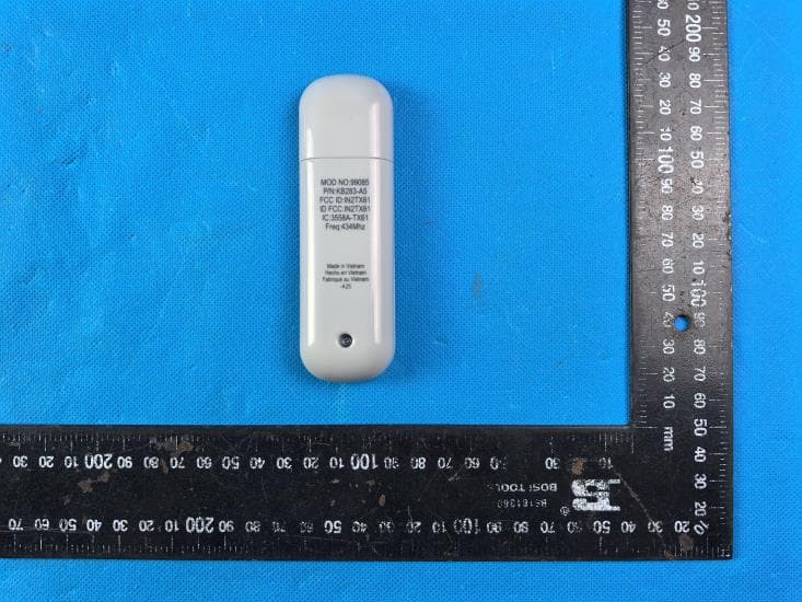
IN2TX61
Sep 11, 2024Remote Control for Ceiling Fan
Equipment Class
DSC - Part 15 Security/Remote Control Transmitter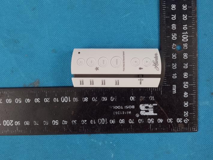
IN2TX57
Jul 03, 2023Remote Control for Ceiling Fan
Equipment Class
DSC - Part 15 Security/Remote Control Transmitter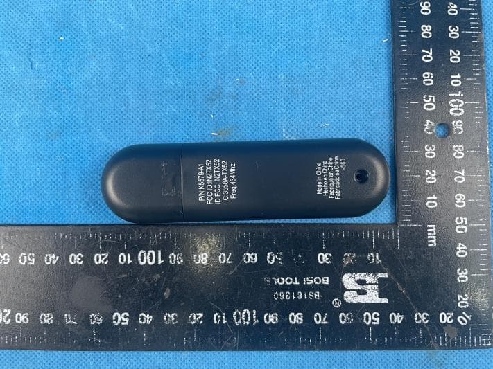
IN2TX52
Jan 10, 2023Remote Control for Ceiling Fan
Equipment Class
DSC - Part 15 Security/Remote Control Transmitter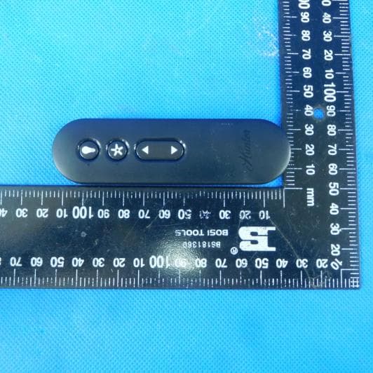
IN2TX50
Jul 29, 2020Remote Control for Ceiling Fan
Equipment Class
DSC - Part 15 Security/Remote Control Transmitter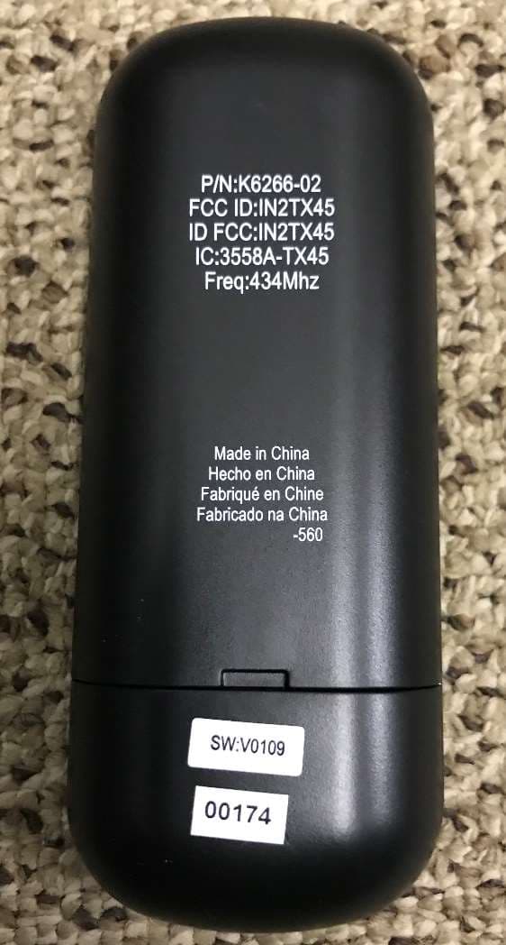
IN2TX49
Jun 14, 2020Remote control for ceiling fan
Equipment Class
DSC - Part 15 Security/Remote Control Transmitter