IN2TX44Plug in remote control for ceiling fan
Hunter Fan Company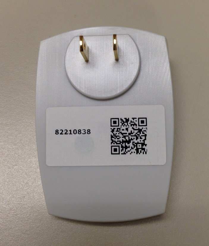
Click to zoom
Application Details
- Equipment Class
- DSC - Part 15 Security/Remote Control Transmitter
- Date of Grant
- Mar 17, 2015
- Application Purpose
- Original Equipment
- Date of Application
- Mar 17, 2015
- Equipment Note
- Plug in remote control for ceiling fan
- Frequency Range
- 434.00000000 - 434.00000000
- Company
- Hunter Fan Company
- Country
- United States
Documents & Files
Document Text
Text extracted from the exhibit documents filed with the FCC. Open a document above to read the original.
Users Manual
M3561-01 • 12/04/14 • © Hunter Fan Company installation and setup guide programmable control model 99107 M3561-01 • 12/04/14 • © Hunter Fan Company 2 If your fan has pull chains, use the pull chains to set the fan speed to HIGH and the light to ON before disconnecting power. 1 Unscrew and lower the canopy. Remove the wire connectors that connect the wires from the ceiling to the fan, leaving the grounding wires connected. If uncertain how to do this, reference the fan’s owner’s manual. Hunter fan manuals can be found on www.HunterFan.com. Note: With wiring exposed, it may be helpful to note existing wire connections or take a digital photo for reference before removing the wire connectors. 3 installation Ensure that power is OFF at the circuit breaker before proceeding with installation. 2 OFF Turn Power M3561-01 • 12/04/14 • © Hunter Fan Company 3 Ceiling Plate Receive r Canopy Receiver Canopy Ceiling Bracket Receiver Fan Body Cable Tie Receiver Canopy Choose the hanging system that most closely resembles the one used by your fan and place the receiver as shown. 4 Note: If your canopy is crowded with excess wire, you may wish to cut the excess fan wires. Leave a minimum of 8 inches remaining. Strip the fan lead wires 1/2 inch. Place remaining excess wire into the ceiling electrical box. The bracket and fan must remain properly grounded. If the fan is installed on an angled ceiling and you need assistance with installation, please call 1-888-830-1326. For low profile fans, secure the receiver to the ceiling bracket with a cable tie. installation (continued) WARNING: This receiver cannot be installed in conjunction with any other receiver or hard-wired wall control. Doing so will void your warranty. Hanging System 1Hanging System 2 Hanging System 3Hanging System 4 M3561-01 • 12/04/14 • © Hunter Fan Company 4 5 Using the wire connectors: • Connect the blue wire from the receiver to the light wire (blue or possibly black with white stripe) from the fan. • Connect the yellow wire from the receiver to the motor wire (black) from the fan. F R O M R E C E I V E R black blue (or black/white stripe) yellow blue F R O M F A N Connect wires from the receiver to wires from the fan as shown. Note: If you’re uncertain about wire colors or connections, please contact a qualified electrician. Turn the connectors upward and push them carefully back through the hanger bracket into the outlet box. Spread the wires apart, with the grounded wires on one side of the outlet box and the ungrounded wires on the other side of the outlet box. To avoid possible electrical shock, before installing or servicing your fan, disconnect the power by turning off the circuit breakers to the outlet box and associated wall switch location. If you cannot lock the circuit breakers in the off position, securely fasten a prominent warning device, such as a tag, to the service panel. installation (continued) M3561-01 • 12/04/14 • © Hunter Fan Company 5 After all wires are connected and secured with wire connectors, reinstall the canopy. If uncertain how to install the canopy, reference the fan’s owner’s manual. F R O M C E I L I N G F R O M R E C E I V E R black white white (grounded) black (ungrounded) white F R O M F A N Connect wires from the fan and receiver to wires from the ceiling as shown. 6 Using the wire connectors: • Connect the black wire (ungrounded) from the ceiling to the black wire from the receiver. • Connect the white wire (grounded) from the ceiling to both the white wire from the receiver and the white wire from the fan. Note: If you’re uncertain about wire colors or connections, please contact a qualified electrician. 7 Restore power at the circuit breaker. 8 installation (continued) Note: If you have a dual switch, please cap the secondary power wire from the ceiling. This will result in one unused switch. M3561-01 • 12/04/14 • © Hunter Fan Company 6 setup Install the app. Visit your app store and search simpleconnect to find the app. 1 Plug in the wall control. Note: You may wish to write down the PIN, which can be found on the wall control. You will need the PIN to complete step 5 on this page. 2 Launch the app. Ensure that Bluetooth® is enabled on your iOS or Android device before launching the app. 3 Tap the Controller button. If you are installing multiple wall controls, be sure to tap the Controller button that coincides with the correct wall control. Enter the PIN. The 4-digit PIN can be found on the wall control. Tap Done when finished. 4 5 Maximum distance from the wall control to the fan/receiver is 80 feet. Congratulations! You have successfully set up your programmable control. You may now begin using the app to take control of your fan! Remember: The app only works while in range of the wall control. If you would like your fan and lights to operate while you are away, you must first use the app to schedule an event. Dimming: In the app, navigate to the “Rooms Configured” settings screen and tap the Gear icon next to your room. Here you can turn the dimming feature on or off. This may cause faulty operation if your bulbs do not support dimming. PIN: M3561-01 • 12/04/14 • © Hunter Fan Company 7 Tap the Gear icon shown below. Be sure to choose a Gear icon for a room that is not already configured. Note: There is a maximum four rooms per wall control. a Gear icon b c Cycle power to the fan. Turn power off and back on at the wall (or circuit breaker if necessary). The next step must be completed WITHIN THREE MINUTES of restoring power to the fan. d Tap OK to confirm pairing. Note: The lights will flash (if applicable) and the fan will turn on at low speed. This is visual confirmation that the pairing was successful. Congratulations! You have successfully set up your additional receiver. Tap the Back button twice to begin using the app to take control of your fan! setup for additional fans If you wish to operate multiple fans with one wall control: 1. You will need an additional receiver (sold separate…
Text truncated - open the document above for the full version.
Cover Letter(s)
January 6, 2015 Federal Communications Commission 445 12 th Street SW Washington, DC 20554 Subject: Limited Agency Agreement Re: IN2TX44 We, Hunter Fan Company, hereby authorized Intertek Testing Services to act as our agent for the purpose of preparing application for FCC ID number IN2TX44 under all applicable parts of the FCC rules and regulations. The effective date of this limited agency agreement is January 6, 2015. The limited agency agreement expires on January 6, 2016 unless sooner terminated or extended by written notice to Intertek Testing Services and the Federal Communications Commission. This is to advise that we are in full compliance with the Anti-Drug Abuse Act. The applicant is not subject to a denial of federal benefits pursuant to Section 5301 of the Anti-Drug Act of 1988, 21 U.S.C. 862, and no party to the application is subject to a denial of federal benefits pursuant to that section. If you have any questions or comments, please do not hesitate to contact me. Sincerely, Julian Martin Compliance Manager Hunter Fan Company 901-248-2810
Cover Letter(s)
1(1) Attention: Application Examiner Re: Request for confidentiality Applicant: Hunter Fan Company FCC ID: IN2TX44 To whom it may concern, Permanent Confidentiality Request is hereby submitted by Hunter Fan Company to withhold permanently from public review certain portions of the application for equipment certification for the referenced FCC identifiers. This request for confidentiality is made pursuant to 47 CFR 0.457(d) and 0.459 of the FCC Rules. In particular, the following sections of the application are to be kept permanently confidential: • Schematics • Detailed Block diagrams • Detailed Operational/Functional Description Rationale for request for confidentiality: Hunter Fan Company has invested considerable time and materials in research and development to produce the referenced product. Disclosure of the permanently confidential portions of this application to competitors would not only give them significant competitive advantages in developing similar products, but would also disclose successful implementation of unpublished, leading edge technology developed by us. The fee for confidentiality has been submitted along with the fee for certification.] If you have questions or need further information, please contact the undersigned. Sincerely, Julian Martin Compliance Manager Hunter Fan Company 901-248-2810
External Photos
External Photos:
ID Label/Location Info
External Photos: Part No. K3768 FCC ID: IN2TX44 Contains FCC ID: 2AB7YVDBTLE24
Internal Photos
Internal Photo: FCC ID: IN2TX44
Test Report
This report is for the exclusive use of Intertek's Client and is provided pursuant to the agreement between Intertek and its Client. Intertek's responsibility and liability are limited to the terms and conditions of the agreement. Intertek assumes no liability to any party, other than to the Client in accordance with the agreement, for any loss, expense or damage occasioned by the use of this report. Only the Client is authorized to permit copying or distribution of this report and then only in its entirety. Any use of the Intertek name or one of its marks for the sale or advertisement of the tested material, product or service must first be approved in writing by Intertek. The observations and test results in this report are relevant only to the sample tested. This report by itself does not imply that the material, product, or service is or has ever been under an Intertek certification program. EMC Report for Hunter Fan on the Controller Page 1 of 32 TEST REPORT Report Number: 101845214DAL-002 Project Number: G101845214 Report Issue Date: December 17, 2014 Product Designation: Fan controller Model(s): K3768 FCC: IN2TX44 IC: 3558A-TX44 Standards: 47 CFR Part 15, Subpart C (15.231 - Periodic operation in the band 40.66-40.70 MHz and above 70 MHz) RSS-210, Issue:2010/12/01 Issue:8 Low Power License-Exempt Radio communication Devices (All Frequency Bands) - Category I Equipment Tested by: Client: Intertek Testing Services NA, Inc. 1809 10 th St. Suite 400 Plano, TX 75074 - USA Hunter Fan Company 7130 Goodlett Farms Pkwy, Suite 400 Memphis, TN 38016 Report prepared by Report reviewed by Shawn K McGuinness Senior EMC Assoc. Engineer Bryan Taylor Team Leader Intertek Report Number: 101845214DAL-002 Issued: 12/17/2014 EMC Report for Hunter Fan on the Controller Page 2 of 32 TABLE OF CONTENTS (OPTIONAL) 1 Introduction and Conclusion .............................................................................................................. 3 2 Test Summary ...................................................................................................................................... 3 3 Description of Equipment Under Test ............................................................................................... 4 4 System setup including cable interconnection details, support equipment and simplified block diagram ........................................................................................................................................................ 5 5 Duty Cycle Determination (FCC 15A - 15.35(c)) ................................................................................ 7 6 Radiated emissions (E-field) for low power intentional radiators ................................................. 15 7 Bandwidth Requirements (FCC 15C - 15.231(c))............................................................................. 21 8 AC Mains Conducted Emissions ...................................................................................................... 24 9 Restrictions (FCC 15C - 15.231(a)) ................................................................................................... 29 10 Revision History ................................................................................................................................... 32 Intertek Report Number: 101845214DAL-002 Issued: 12/17/2014 EMC Report for Hunter Fan on the Controller Page 3 of 32 1 Introduction and Conclusion The tests indicated in section 2.0 were performed on the product constructed as described in section 3.0. The remaining test sections are the verbatim text from the actual data sheets used during the investigation. These test sections include the test name, the specified test Method, a list of the actual Test Equipment Used, documentation Photos, Results and raw Data. No additions, deviations, or exclusions have been made from the standard(s) unless specifically noted. Based on the results of our investigation, we have concluded the product tested complies with the requirements of the standard(s) indicated. The results obtained in this test report pertain only to the item(s) tested. 2 Test Summary Section Test full name Test date Result 3 Description of Equipment Under Test 4 System setup including cable interconnection details, support equipment and simplified block diagram 5 Duty Cycle Determination (FCC 15A - 15.35(c)) Pass 6 Radiated emissions (E-field) for low power intentional radiators Pass 7 Bandwidth Requirements (FCC 15C - 15.231(c)) Pass 8 Conducted Emissions Pass 9 Restrictions (FCC 15C - 15.231(a)) Pass Intertek Report Number: 101845214DAL-002 Issued: 12/17/2014 EMC Report for Hunter Fan on the Controller Page 4 of 32 3 Description of Equipment Under Test Equipment Under Test Description Manufacturer Model Number Serial Number SimpleConnect Fan Controller Hunter Fan Company K3768 10771038 SimpleConnect Fan Controller Hunter Fan Company K3768 10782055 Receive Date: 11-17-2014 Received Condition: Good Type: Production Description of Equipment Under Test (provided by client) The SimpleConnect K3768 is a blue tooth low energy device (BTLE) indoor overhead fan remote control. EUT simply plugs into a 120VAC/60Hz Wall Receptacle and is operated by a signal from a smartphone. Transmitter Overview: FCC Identifier IN2TX44 IC Identifier 3558A-TX44 Frequency Range 433MHz Modulation SAW Modulation Antenna type (15.203) Integral Equipment Under Test Power Configuration Rated Voltage Rated Current Rated Frequency Number of Phases 120VAC 0.018A 60Hz Single Operating modes of the EUT: No. Descriptions of EUT Exercising 1 For radiated testing, EUT was programmed to operate at a steady repeat in its normal modulation scheme. 2 For Duty Cycle and BW testing, EUT was programmed to operate in its normal mode and modulation scheme. NOTE: During testing EUT was identified by its production project number, 99108. Intertek Report Number: 101845214DAL-002 Issued: 12/17/2014 EMC Report for Hunter …
Text truncated - open the document above for the full version.
Test Setup Photos
Test Setup Photos FCC ID: IN2TX44
Contact Information
Applicant
Julian A Martin(Compliance Manager)
Technical Contact
Hunter Fan CompanyJulian Andre Martin
[email protected]901-248-2810
7130 Goodlett Farms Pkwy, Suite 400 · Memphis, Tennessee · United States
Non-Technical Contact
Hunter Fan CompanyJulian Andre Martin
[email protected]901-248-2810
Test Firm
Intertek Testing Services NA, Inc.Paul Coghill
Technical Specifications
| # | Rule Parts | Frequency Range | Power Output |
|---|---|---|---|
| 1 | 15.231 | 434 MHz - 434 MHz | - |
Other Applications from Hunter Fan Company
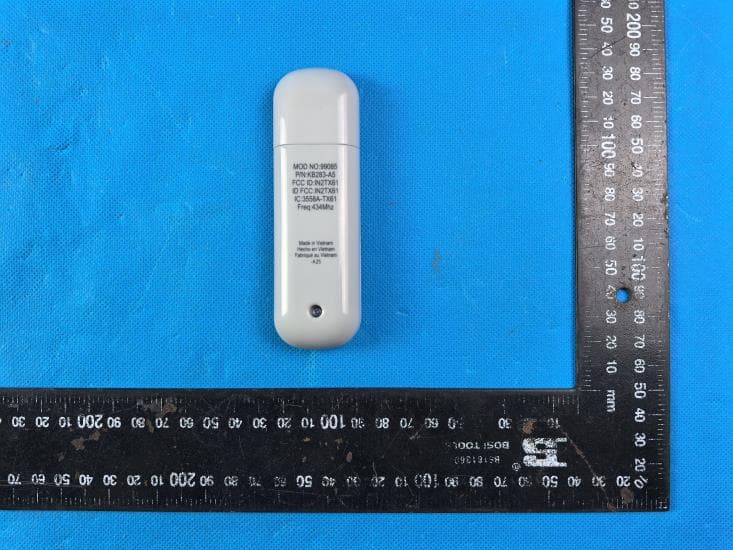
IN2TX61
Sep 11, 2024Remote Control for Ceiling Fan
Equipment Class
DSC - Part 15 Security/Remote Control Transmitter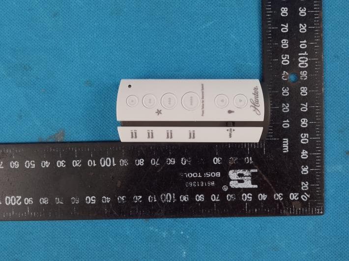
IN2TX57
Jul 03, 2023Remote Control for Ceiling Fan
Equipment Class
DSC - Part 15 Security/Remote Control Transmitter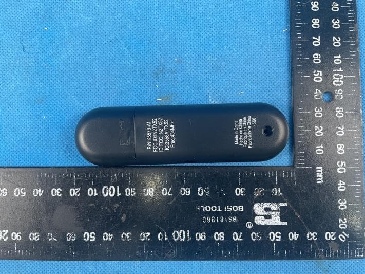
IN2TX52
Jan 10, 2023Remote Control for Ceiling Fan
Equipment Class
DSC - Part 15 Security/Remote Control Transmitter
IN2TX50
Jul 29, 2020Remote Control for Ceiling Fan
Equipment Class
DSC - Part 15 Security/Remote Control Transmitter
IN2TX49
Jun 14, 2020Remote control for ceiling fan
Equipment Class
DSC - Part 15 Security/Remote Control Transmitter