IN2TX70Remote Control Transmitter
Hunter Fan Company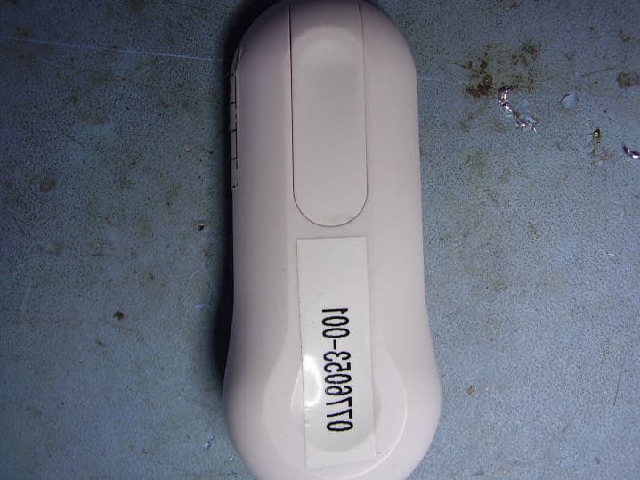
Click to zoom
Application Details
- Equipment Class
- DSC - Part 15 Security/Remote Control Transmitter
- Date of Grant
- Jun 21, 2006
- Application Purpose
- Original Equipment
- Date of Application
- Jun 21, 2006
- Equipment Note
- Remote Control Transmitter
- Frequency Range
- 350.00000000 - 350.00000000
- Company
- Hunter Fan Company
- Country
- United States
Documents & Files
Document Text
Text extracted from the exhibit documents filed with the FCC. Open a document above to read the original.
Users Manual
InstallatIon Just RIght DIgItal theRmostat If the code letter on your existing thermostat is. . . then mark the wire with label shown. . . and connect to thermostat terminal shown RH, R, VR or 4 24 Volt RC, VC 24 Volt Cool G or F Fan Y, C or M Air Conditioning Compressor W or H Heating Form No. 41970-01 Rev 6/5/2006 Low Battery Indicator: Flashes when batteries need to be replaced. System Switch: Selector switch for Heat, Cool, and Off. Fan Switch: Fan switch for Automatic or Continuous fan operation. Battery Compartment: Front access allows easy insertion of two AA 1.5V batteries. Up and Down Keys: Keys for changing the Temperature setting. Also used for adjust- ing the Span. Filter Key: Resets the filter change counter to zero. Reset: Press with a paper clip to reset the thermostat and return to power-up settings. Front Doors: Covers keys and batteries when not used for neat appearance. Open with one finger from top or bottom. LCD Display: Shows Room Temperature, Set Temperature, and other feature information as required. Filter Change Indicator: Flashes when filter needs to be checked. Congratulations! Your new Hunter thermostat will provide years of reliable service. Using this digital thermostat will provide more uniform comfort in your home through the seasons. Thank you for buying a Hunter product! Please read this manual for complete instructions on installing and operating your thermostat. If you require further assistance, call Hunter Technical Support at 1-888-830-1326 from 8am to 5pm Central Time. Remove the mylar label from the display window. ImpoRtant InfoRmatIon 1. This thermostat is designed to work on the following systems: • Gas - Standing Pilot • Gas - Electronic Ignition • Gas - Fired Boilers • Gas - Milivolt Systems • Oil - Fired Boilers • Oil - Fired Furnace • Electric Furnace • Electric Air Conditioning This thermostat will NOT control single-stage or multi-stage heat pumps or 110/220 V baseboard electric heating systems. 2. temperature Range This thermostat can be set between 45°F and 95°F (7°C and 35°C). However, it will display room temperatures from 30°F to 99°F (0°C and 37°C). “HI” will be displayed if the temperature is higher than 99°F (37°C), and “LO” will be displayed if the temperature is lower than 30°F (0°C). This thermostat will automatically cutoff in Heat mode if the temperature rises above 95°F (35°C), and automatically cutoff in Cool mode if the temperature drops below 45°F (7°C). 3. Compressor protection This thermostat provides a 3.5 minute delay after shutting off the cooling system before it can be restarted. This feature will prevent damage to your compressor caused by rapid cycling. It does not prevent a rapid compressor restart due to short power outages. 4. Battery Warning Two fresh AA alkaline batteries should provide well over one year of service. However, when the batteries become drained, the Low Battery Indicator will flash on the display. When this message occurs, install new alkaline batteries. You have approximately 1 minute to change the batteries and keep the thermostat’s settings. Once the batteries have become too low to ensure proper operation, your system will be turned Off, and the display will be cleared except for flashing Low Battery Indicator on the LCD display. CAUTION: When only the battery icon flashes on the display, the ther- mostat is shut down, and your system will no longer operate. In this condition, there is no temperature control of your dwelling. NOTE: If you plan to be away from the premises over 30 days, we recommend that you replace the old batteries with new alkaline batteries prior to leav- ing. 5. notes This device complies with Part 15 of the FCC Rules. Operation is subject to the following two conditions: (1) this device may not cause harmful interference, and (2) this device must accept any interference received, including interference that may cause undesired operation. This equipment has been tested and found to comply with the limits for a Class B digital device, pursuant to Part 15 of the FCC Rules. These limits are designed to provide reasonable protection against harmful interference in a residential installation. This equipment generates, uses and can radiate radio frequency en- ergy and, if not installed and used in accordance with the instructions, may cause harmful interference to radio communications. However, there is no guarantee that interference will not occur in a particular installation. If this equipment does cause harmful interference to radio or television reception, which can be determined by turning the equipment off and on, the user is encouraged to try to correct the interference by one or more of the following measures: • Reorient or relocate the receiving antenna. • Increase the separation between the equipment and receiver. • Connect the equipment into an outlet on a circuit different from that to which the receiver is connected. • Consult the dealer or an experienced radio/TV technician for help. featuRes What You need This thermostat includes two #8 slotted screws and two wall anchors for mounting. To install your thermostat, you should have the fol- lowing tools and materials. • Slotted Screwdriver(s) • Small Philips screwdriver • Hammer • Electric drill and 3/16” bit • Two 1.5 V (AA) size alkaline batteries Remove old thermostat CAUTION: Do not remove any wiring from existing thermostat before reading the instructions carefully. Wires must be labeled prior to removal. IMPORTANT! Turn off the power to the furnace at the main power panel or at the furnace. Remove existing thermostat cover and thermostat. See Figure 1. Some ther- mostats will have screws or other locking devices that must first be removed. Once the wall mounting plate is exposed, look for wires. If wires are not visible, they may be connected to the back of the wallplate. Again, look for screws, tabs, etc. Some models have doors that open to expose wires and mounting screws. See Figure 1. Wire labeling • E…
Text truncated - open the document above for the full version.
External Photos
Project: 06CA05511 Underwriters Laboratories, Inc. Issued: 04/27/06 File: MC1324 Test Report on Electromagnetic Compatibility Page 1 of 2 Test Report: 060036 External Photo – Front Project: 06CA05511 Underwriters Laboratories, Inc. Issued: 04/27/06 File: MC1324 Test Report on Electromagnetic Compatibility Page 2 of 2 FCC ID: IN2TX70 Internal Photos IC: 3558A-HCT01 External Photo – Rear
Internal Photos
Project: 06CA05511 Underwriters Laboratories, Inc. Issued: 04/27/06 File: MC1324 Test Report on Electromagnetic Compatibility Page 1 of 5 Test Report: 060036 Internal Photo – Button Side detail Project: 06CA05511 Underwriters Laboratories, Inc. Issued: 04/27/06 File: MC1324 Test Report on Electromagnetic Compatibility Page 2 of 5 FCC ID: IN2TX70 Internal Photos IC: 3558A-HCT01 Internal Photo – Reverse side detail Project: 06CA05511 Underwriters Laboratories, Inc. Issued: 04/27/06 File: MC1324 Test Report on Electromagnetic Compatibility Page 3 of 5 FCC ID: IN2TX70 Internal Photos IC: 3558A-HCT01 Internal Photo – Cover open showing keypad side and battery door Project: 06CA05511 Underwriters Laboratories, Inc. Issued: 04/27/06 File: MC1324 Test Report on Electromagnetic Compatibility Page 4 of 5 FCC ID: IN2TX70 Internal Photos IC: 3558A-HCT01 Internal Photo – Cover open showing reverse side and battery door Project: 06CA05511 Underwriters Laboratories, Inc. Issued: 04/27/06 File: MC1324 Test Report on Electromagnetic Compatibility Page 5 of 5 FCC ID: IN2TX70 Internal Photos IC: 3558A-HCT01
Operational Description
Operation Theory – Transmitter - Model 42996 Model 42996 Thermostat RF transmitter operates the associated receiver/thermostat by means of a pulse modulated radio/frequency signal operating at 350 MHz. The transmitter’s two buttons permit the user to adjust the temperature setting up or down. A four-position DIP switch permits the user to encode the signal for one of 16 possible combinations. The signal pattern consists of a series of long or short pulses as follows: The duration of each pulse, along with the period between the bursts, is detailed in the test report. The antenna is integrated and not adjustable or detachable by the user. Output power and frequency are fixed and not adjustable by the user.
Schematics
123456 A B C D 654321 D C B A Title NumberRevisionSize B Date:30-Mar-2006Sheet of File:F:\b86r\Backup of B86R RF Transmitter 433M.DDBDrawn By: Q201 2SC3556 C204 18P C201 2.2P C208 820P R206 47R R205 68R R204 220K SAW1 350MHZ L1 5T HUNB86R TX Sunny Zhou 01 1 of 1 VCC R202 1.5M VSS 6 DOUT 14 OSC2 12 OSC1 13 VDD 15 A0 16 A1 17 A2 18 A3 1 A4 2 A5 3 A6 4 A7 5 AD8 7 AD9 8 AD10 9 AD11 10 /TE 11 U201 HT12E 1 2 3 45 6 7 8 S201 WARMER COOLER D201 1N4148 D203 1N4148 R207 100K Q202 3904 R208 100K Q203 3904 R210 3K R203 51k VCCVCC VCC C203 0.1UF VCC BAT 12V BATTERY C202 0.1uF LED202 LED RED LED203 LED BLUE C205 1UF/16v C206 1UF/16v R209 2.2K C207 8.2P C209 8.2P C210 20P C212 NC L2 5T D204 IN4148 R211 470K R212 470K D202 IN4148 Q206 3904 Q204 3904 ANT
Test Setup Photos
Project: 06CA05511 Underwriters Laboratories, Inc. Issued: 04/27/06 File: MC1324 Test Report on Electromagnetic Compatibility Page 14 of 32 Test Report: 060036 Test 1, Item A (Flat Orientation) - Test Set-Up Photo: Radiated Disturbance Emissions - 30 MHz to 1000 MHz
Contact Information
Applicant
Julian A Martin(Compliance Manager)
Technical Contact
Hunter Fan CompanyRobert Davis
[email protected]901-248-2212
2500 Frisco Avenue · Memphis, Tennessee · United States
Non-Technical Contact
Hunter Fan CompanyRobert Davis
[email protected]901-248-2212
Test Firm
UL LLCRick Titus
Technical Specifications
| # | Rule Parts | Frequency Range | Power Output |
|---|---|---|---|
| 1 | 15.231,15.231(e) | 350 MHz - 350 MHz | - |
Other Applications from Hunter Fan Company
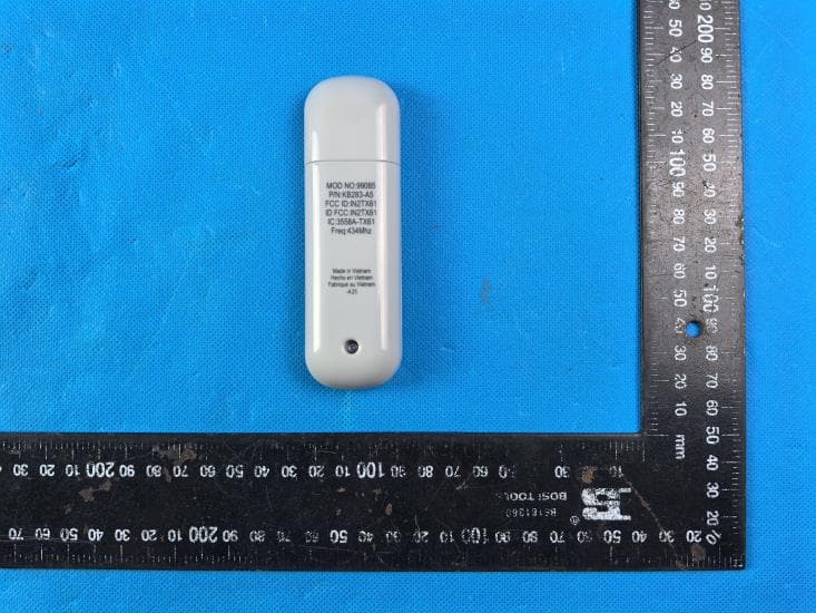
IN2TX61
Sep 11, 2024Remote Control for Ceiling Fan
Equipment Class
DSC - Part 15 Security/Remote Control Transmitter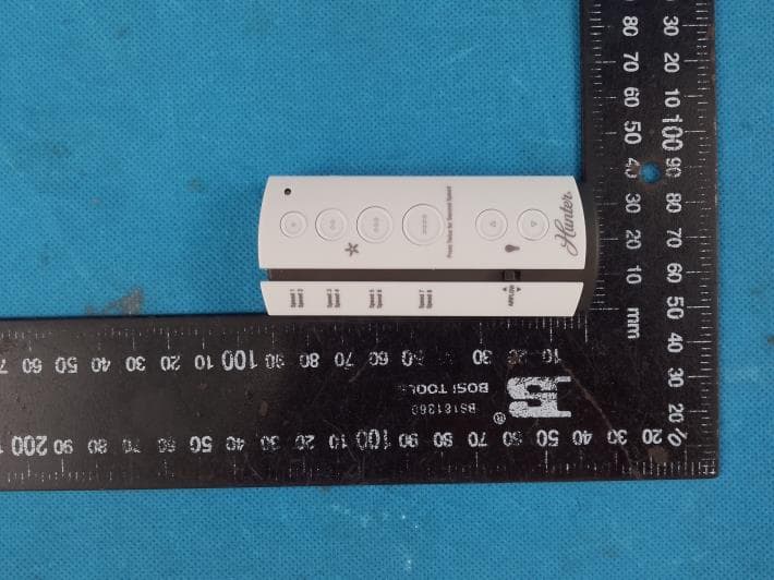
IN2TX57
Jul 03, 2023Remote Control for Ceiling Fan
Equipment Class
DSC - Part 15 Security/Remote Control Transmitter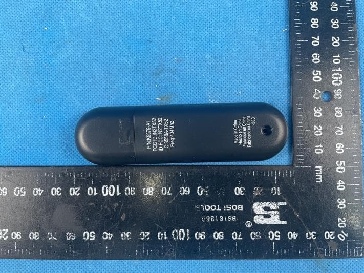
IN2TX52
Jan 10, 2023Remote Control for Ceiling Fan
Equipment Class
DSC - Part 15 Security/Remote Control Transmitter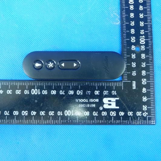
IN2TX50
Jul 29, 2020Remote Control for Ceiling Fan
Equipment Class
DSC - Part 15 Security/Remote Control Transmitter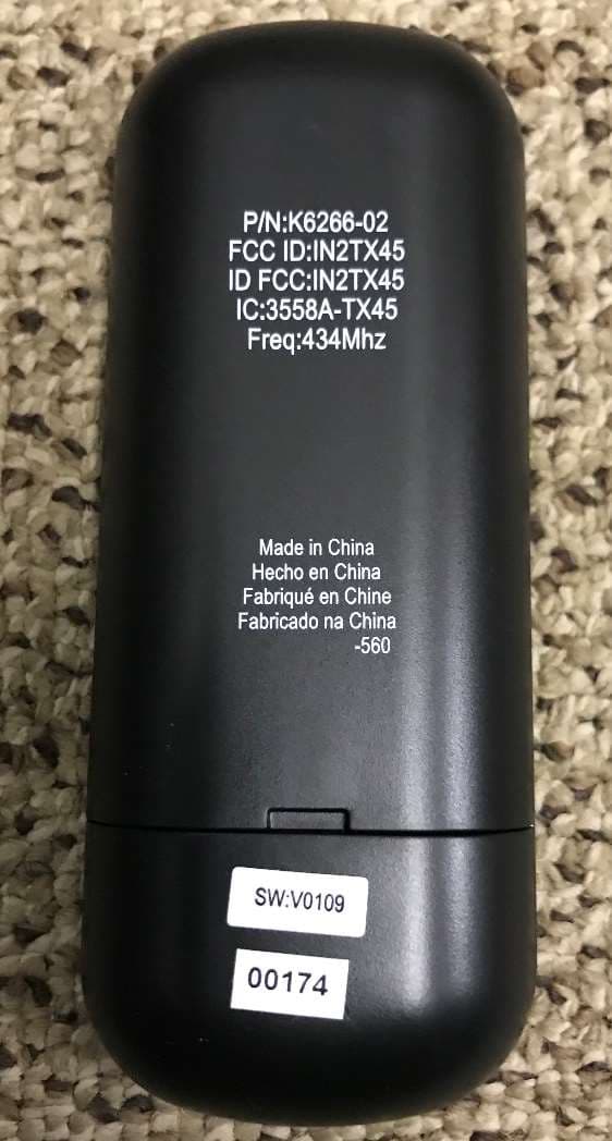
IN2TX49
Jun 14, 2020Remote control for ceiling fan
Equipment Class
DSC - Part 15 Security/Remote Control Transmitter