IN2TXICTWireless Thermostat
Hunter Fan Company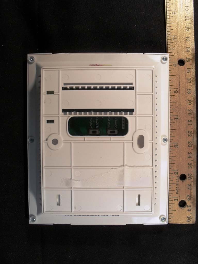
Click to zoom
Application Details
- Equipment Class
- DTS - Digital Transmission System
- Date of Grant
- Aug 14, 2012
- Application Purpose
- Original Equipment
- Date of Application
- Aug 14, 2012
- Equipment Note
- Wireless Thermostat
- Frequency Range
- 908.00000000 - 920.00000000
- Company
- Hunter Fan Company
- Country
- United States
Documents & Files
Document Text
Text extracted from the exhibit documents filed with the FCC. Open a document above to read the original.
Users Manual
Alternatively, you may want to take a picture of the wires on your old thermostat for reference. If you have any wire codes that do not match the Hunter labels, you may have a system that does not conform to industry standard. Call our Technical Support at 1-888-830-1326. Getting Started 1. Power OFF Your HVAC System Unit You will need a Phillips head screwdriver to complete this installation. Read and save these instructions! If you still need assistance after reading this manual, call our Technical Support at USA: 1-888-830-1326 Canada: 1-866-268-1936 This thermostat is compatible with most 24V AC/millivolt systems with a maximum of 1 amp including: conventional oil, gas, electric, hot water systems, single stage, and multi-stage heat pumps. This thermostat will not control line voltage systems running 110V. Higher amp or line voltage systems will increase the risk of fire. *This device complies with part 15 of the FCC Rules. Operation is subject to the following two conditions: (1) This device may not cause harmful interference, and (2) this device must accept any interference received, including interference that may cause undesired operation. *This device complies with RSS-GEN IC: Operation is subject to the following two conditions: (1) this device may not cause interference, and (2) this device must accept any interference, including interference that may cause undesired operation of the device. *Any alteration of this product, either intentional or unintentional, not expressly approved by the manufacturer could result in operation failure of the device, inability to gain assistance from our technical team, or manufacturer refusing warranty support. *This Class B digital apparatus complies with Canadian ICES-003. *Only 1 reversing valve is needed to run a heat pump. If both “O” and “B” are present, “B” may be a common wire. Expose your existing thermostat wires. Locate the wire terminals. If the wire terminals are not visible, they may be connected to the back of the wall plate. Remove the existing wall plate and/or thermostat. Label your wires. As you remove each wire one at a time, find the Hunter label with the corresponding letter code and attach it to the wire. DO NOT DISCONNECT THE WIRES BEFORE LABELING THEM 3. Mounting Your Wall Plate Insert the wires. Pass your labeled wires through the opening of the wall plate. Separate the wall plate. Pull the wall plate straight off the back of your thermostat. RH, R Power wire for heating Install the top screw. Partially tighten one screw into the top hole. Level the wall plate. Install the bottom screw. Fully tighten both screws. Go to your circuit breaker panel and turn off power to your compressor and furnace. Wire Identification OFF Turn Power A C C D 2. Labeling Your Wires AB RC Power wire for air conditioning Y, Y1 Controls your compressor outside G Controls your fan to your HVAC system W Furnace wire L Allows the heat pump to tell the thermostat there may be a system problem O Reversing valve for the heat pump; allows compressor to supply air conditioning* B Alternate reversing valve for the heat pump; allows compressor to supply heat* W2 - Second stage of heat E - Emergency heat Aux - Auxiliary wire Y2 Second stage of cooling C Common wire used to power the thermostat when available A Only used with a 3 wire hot water heating system Pre-Installed Jumper Clip Tip: You may need a precision screwdriver (smaller tip) to detach wires from your old thermostat. Tip: To prevent your wires from falling back into the wall, wrap them around a pencil. B Internet Thermostat Installation Guide If you only have an RH wire, leave the pre-installed jumper clip in place between the RC & RH terminals. Install the wire under the jumper clip in the same opening. If you have both an RC & RH wire, lift the RC & RH levers and remove the pre-installed jumper clip now. 4. Reconnecting Your Wires5. Mounting Your Thermostat Raise the appropriate terminal levers. Lift the levers on the terminals that match the labels on your wires. If one of the terminals you need has a shield in front of it, use your finger to break the tab away. Insert your wires and lower the levers. Insert each wire into its corresponding terminal. Lower the levers and push any excess wire back into the wall. OPTION 1 OPTION 2 Snap your thermostat onto the wall plate. D Install your AA batteries. Note: NEVER use rechargeable batteries. C Write down your 15-digit security code exactly as displayed. You will need this code when you setup your account. B A Set your system switches. Based on the type of furnace you have: - Select Gas/Oil or Electric - Select Heat Pump or Conventional 6. Power ON Your HVAC System Unit You have completed your installation! Go to your circuit breaker panel and turn on power to your compressor and furnace. ON Turn Power Form# 44123-01 20120814 ©2012 Hunter Fan Co. EXAMPLE Control from any smart phone, tablet, laptop or desktop computer. my.HunterFan.com OR When the gateway light turns green, your thermostat will automatically connect to the internet. modem/router Tip: Lift gateway antenna to improve connectivity. 7. Connect 8. Register 9. Control If you are not sure what system you have, contact your HVAC manufacturer. À titre de référence, on peut aussi prendre une photo des fils de l’ancien thermostat. Si les codes de fil sont différents des étiquettes Hunter, il est possible que le système ne soit pas conforme aux normes du secteur. Appeler l’assistance technique au 1-888-830-1326. Pour commencer 1. Arrêter le système CVC Un tournevis cruciforme sera nécessaire pour effectuer cette installation. * Seulement 1 soupape d’inversion est nécessaire pour faire fonctionner une pompe à chaleur. Si « O » et « B » sont tous les deux présents, « B » peut être un fil commun. Exposer les fils du thermostat existant. Trouver les bornes de fils. Si les fils ne sont pas visibles, c’est qu’ils peuvent être raccordés à l’arrière de la plaque murale. Retirer la plaque murale…
Text truncated - open the document above for the full version.
Block Diagram
1 1 2 2 3 3 4 4 5 5 6 6 DD CC BB AA Connected Thermostat P3003-HF-100- A 8/10/2012C 1 1 BKB DO NOT SCALE DRAWING DATE DWG NO. DRAWNBY PAGE SCALE DESCRIPTION/PART NAME This drawing or material is submitted to you with confidence that it will be used only for your information on application engineering studies and shall never be used in any manner detrimental to our interest PROPRIETARY AND CONFIDENTIAL MATERIAL phone: 615-654-9710 White House, TN 37188 email: [email protected] 2009 Skyhawk Court VIPER Design Description 1.0BKBInitial Release DateByRev 8/09/12 BLOCK DIAGRAM UNLESS OTHERWISE SPECIFIED Main Controller PIC24F Radio SOIC CC1110 ControlControlRF Antenna Matching Circuit Wire Antenna 26.0 Mhz Internal 8.0 Mhz 32.164kH z PLL Freqency Selector LCD Screen & Backlight Harness Power Input D155 BAT54 D154 BAT54 D151 BAT54 VinAC BT 2 AA AC/DC Power Supply BT 1 AA BT 4 AA BT 3 AA DC Power Supply Vdd Vdd Vdd Relay Circuit Harness DC Power Supply Vlcd Input B utton s Switches Harness Thermistor Flash
Cover Letter(s)
1(2) Attention: Application Examiner Re: Request for confidentiality Applicant: Hunter Fan Company FCC ID: IN2 To whom it may concern, Request is hereby submitted by Hunter Fan Company to withhold from public review for a period of 45 days from the date of the Grant of Equipment Authorization and prior to marketing, certain portions of the application for equipment certification for the referenced FCC identifiers. This request for confidentiality is made pursuant to 47 CFR 0.457(d) and 0.459 of the FCC Rules. In particular, the following sections of the application are to be kept confidential for a period of 45 days from the date of Authorization: • Schematics • Detailed Block diagrams • Detailed Operational/Functional Description • Tune up procedure • Parts list • Test setup photos • External photos (NOTE: External photos can only be held for short-term confidentiality) • Internal photos • User manual Rationale for request for confidentiality: Hunter Fan Company has invested considerable time and materials in research and development to produce the referenced product. Disclosure of the short-term confidential portions of this application during the period of importation and/or distribution would reveal key aspects of proprietary technology to competitors and diminish the value of our investment in research and development.] If you have questions or need further information, please contact the undersigned. Sincerely, Manager of Compliance Engineering Hunter Fan Company 2(2)
Operational Description
Hunter Fan Company Home Comfort Group 7130 Goodlett Farms Pkwy, Suite 400 Memphis, TN 38016 Page 1 of 25 Home Comfort Thermostat – Product Specification 2011 eComfort Thermostat Hunter Fan Company Home Comfort Group 7130 Goodlett Farms Pkwy, Suite 400 Memphis, TN 38016 Page 2 of 25 Page 2 of 25 Revision History Version Date Prepared By Changes X1 Shain Breland Initial draft X2 1/31/2012 Andy Lin Update highlighted in yellow. X3 15Feb12 Viper/SB Multiple additions X4 25Jul12 SB Removed proprietary comm info for FCC submittal Hunter Fan Company Home Comfort Group 7130 Goodlett Farms Pkwy, Suite 400 Memphis, TN 38016 Page 3 of 25 Page 3 of 25 Table of Contents 1. Purpose .............................................................................................................................................................................. 5 2. Scope ................................................................................................................................................................................. 5 3. APPLICABLE DOCUMENTS ......................................................................................................................................... 5 3.1. Codes Agency Standards .......................................................................................................................................... 5 3.2. Hunter Fan Standards ............................................................................................................................................... 5 3.3. Third Party Standards ............................................................................................................................................... 5 3.3.2. IPC Standards ........................................................................................................................................................... 6 4. E’comfort System Overview ............................................................................................................................................. 7 5. THERMOSTAT PERFORMANCE REQUIREMENT .................................................................................................... 8 5.1. HVAC System Compatibility ................................................................................................................................... 8 5.2. Thermostat Power Supply ...................................................................................................................................... 10 5.3. System Configurations by User .............................................................................................................................. 10 5.4. System Operation Modes ....................................................................................................................................... 11 5.5. Fan Operation Modes ............................................................................................................................................. 11 5.6. Safety Features ....................................................................................................................................................... 11 5.7. User Features .......................................................................................................................................................... 12 5.8. Electrical Requirement ........................................................................................................................................... 12 5.9. Mechanical Requirement ........................................................................................................................................ 16 5.10. Environmental Requirement ................................................................................................................................... 17 6. SOFTWARE ................................................................................................................................................................... 17 6.1. Software Features and Functions ............................................................................................................................ 17 6.2. Control Pattern ....................................................................................................................................................... 17 6.3. Software Requirement ............................................................................................................................................ 22 7. FACTORY TEST AND DIAGNOSTIC MODE ............................................................................................................ 23 7.1. Key Sequence to Enter ........................................................................................................................................... 23 7.2. Diagnostic Sequence .............................................................................................................................................. 23 8. FACTORY DEFAULT SETTINGS ............................................................................................................................... 24 9. PACKAGING REQUIREMENT .................................................................................................................................... 24 9.1. Packaging ............................................................................................................................................................... 24 9.2. Packaging Accessories ........................................................................................................................................... 24 9.3. Product Labels ........................................................................................................................................................ 24 Hunter Fan Company Home Comfort Group 7130 Goodlett Farms Pkwy, Suite …
Text truncated - open the document above for the full version.
Test Report
Client: Product Designation: US: 44917 Canada: 47417, 47418, 47419 and 47420 Report Number: 100841385ATL-001 All services undertaken are subject to the following general policy: This report is for the exclusive use of Intertek's Client and is provided pursuant to the agreement between Intertek and its Client. Intertek's responsibility and liability are limited to the terms and conditions of the agreement. Intertek assumes no liability to any party, other than to the Client in accordance with the agreement, for any loss, expense or damage occasioned by the use of this report. Only the Client is authorized to copy or distribute this report and then only in its entirety. Any use of the Intertek name or one of its marks for the sale or advertisement of the tested material, product or service must first be approved in writing by Intertek. The observations and test results in this report are relevant only to the sample tested. This report by itself does not imply that the material, product, or service is or has ever been under an Intertek certification program. This report must not be used to claim product endorsement by A2LA, NIST, or any agency of the US Government. Tested by: Tests performed by:Report reviewed by: Standard: Jeremy O. Pickens Senior Staff Engineer Richard C. Bianco EMC Team Leader Hunter Fan Com pany 7130 Goodlett Farms Parkway, Ste 400 Memphis, TN 38016 Contact: Robert Davis Phone: 901-248-2212 Fax: 901-248-2382 [email protected] TEST REPORT August 14, 2012 Intertek Testing Services NA Inc. 1950 Evergreen Blvd., Suite 100 Duluth, GA 30096 FCC 15.247 and RSS-210, Issue 8, 2010 Frequency Hopping and Digital Modulation Systems operatin within the bands 902-928 MHz, 2400-2483.5 MHz, and 5725-5850 MHz CFR, Title 47, Chapter I, Part 15 Subpart B ICES-003, Issue 4, 2004 Page 1 of 47EMC Report for Hunter Fan Company on the US: 44917 Canada: 47417, 47418, 47419 and 47420 08/14/2012Report Number: 100841385ATL-001Issued: Intertek 2.0 Test Summary 1.0 Introduction and Conclusion Test DateTest Full NameResultSection System setup including cable interconnection details, support equipment and simplified block diagram. (System Setup)4.0 Transmitter Information for equipment operating under Parts 11, 15 and 18 of the rules (Transmitter Info - Unlicensed)5.0 08/07/2012FCC 15.247 6dB Bandwidth (211759)PASS6.0 08/07/2012FCC Part 15.247(b)(3) / RSS-210 A8.4(4) (Peak Output Power)PASS7.0 08/02/2012FCC Part 15.247(e) / RSS-210 A8.2(2) (Power Spectral Density)PASS8.0 08/07/2012FCC Part 15.247(d) / RSS-210 A8.5 - Conducted (Conducted Spurious Emissions)PASS9.0 08/06/2012FCC Part 15.247(d) / RSS-210 A8.5 - Radiated (Radiated Spurious Emissions)PASS10.0 08/07/2012Additional provisions to the general radiated emission limitations. (FCC 15C - 15.215)PASS11.0 The tests indicated in section 2.0 were performed on the product constructed as described in section 3.0. The remaining test sections are the verbatum text from the actual data sheets used during the investigation. These test sections include the test name, the specified test Method, a list of the actual Test Equipment Used, documentation Photos, Results and raw Data. No additions, deviations, or exclusions have been made from the standard(s) unless specifically noted. Based on the results of our investigation, we have concluded the product tested complies with the requirements of the standard(s) indicated. The results obtained in this test report pertain only to the item(s) tested. Page 2 of 47EMC Report for Hunter Fan Company on the US: 44917 Canada: 47417, 47418, 47419 and 47420 08/14/2012Report Number: 100841385ATL-001Issued: Intertek 3.0 Description of Equipment Under Test Equipment Under Test Description Manufacturer Model Number Serial Number iSTAT T hermostat Hunter Fan 44917 * Not Labeled * 47417, 47418, 47419 and 47420 are Canadian models and are electrically equivalent to the tested model EUT receive date: July 30, 2012 EUT receive condition: Good Description of EUT provided by Client: The thermostat connects to HVAC systems via traditional wired connections. It controls the HVAC system’s heating and cooling cycles via user inputs or automated set points adjustment t hrough a proprietary cloud computing algorit hm. The thermost at communicates to a gateway via a propri etary 900MHz radio frequency communication protocol for data exchange to the cloud servers. The gateway is connected to a WIFI router via wired Ethernet connection. The gateway also requires an AC power adapter for power supply. Cloud computing servers are utilized to collect thermostat data and also allow users to logon to the servers via web applications to program and manage the thermostat from a computer or mobile device. Internet access is required for users to program and manage the thermost at through a comput er or mobile device. Description of EUT exercising: During emissions testing, the EUT was powered from four, new AA batteries. To facilitate measurements, the EUT was configured to continuously transmit a modulated carrier. Low, middle, and high channels were evaluated. Page 3 of 47EMC Report for Hunter Fan Company on the US: 44917 Canada: 47417, 47418, 47419 and 47420 08/14/2012Report Number: 100841385ATL-001Issued: Intertek System setup including cable interconnection details, support equipment and simplified block diagram. (System Setup) 4.0 Method: Record the details of EUTcabling, document the support equipment, and show the interconnections in a block diagram. Data: EUT A Setup Diagram Drawing: Page 4 of 47EMC Report for Hunter Fan Company on the US: 44917 Canada: 47417, 47418, 47419 and 47420 08/14/2012Report Number: 100841385ATL-001Issued: Intertek System setup including cable interconnection details, support equipment and simplified block diagram. (System Setup) 4.0 A Description EUT Cabling Connection Length Shielding FerritesIDFromTo Thermostat (EUT)UnterminatedAppliance Wiring (x8)1mNoneNone Support Equipment DescriptionManufacturerModel NumberS…
Text truncated - open the document above for the full version.
Contact Information
Applicant
Julian A Martin(Compliance Manager)
Test Firm
Intertek Testing Services NA Inc.Charles Parker
Technical Specifications
| # | Rule Parts | Frequency Range | Power Output |
|---|---|---|---|
| 1 | 15C | 908 MHz - 920 MHz | 10.50 mW |
Other Applications from Hunter Fan Company
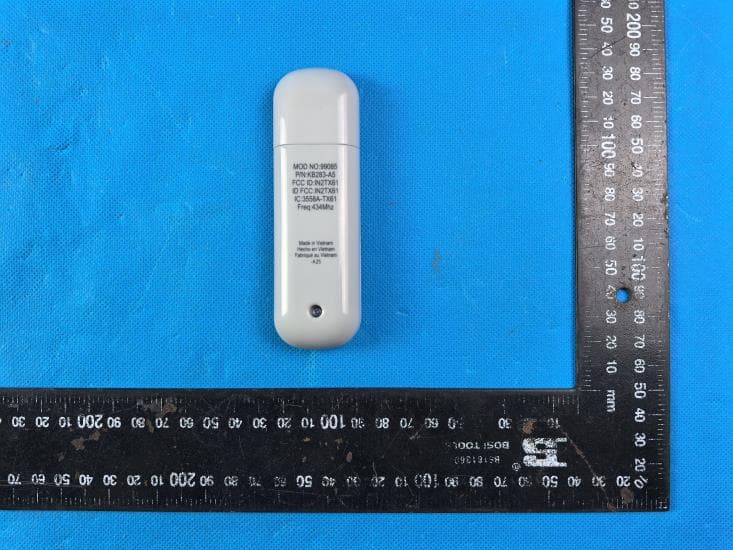
IN2TX61
Sep 11, 2024Remote Control for Ceiling Fan
Equipment Class
DSC - Part 15 Security/Remote Control Transmitter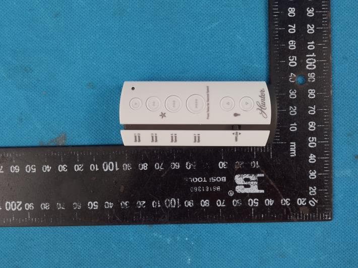
IN2TX57
Jul 03, 2023Remote Control for Ceiling Fan
Equipment Class
DSC - Part 15 Security/Remote Control Transmitter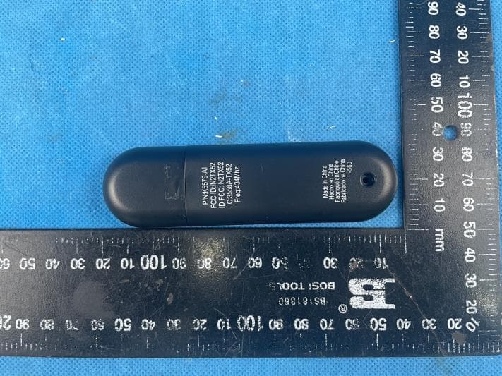
IN2TX52
Jan 10, 2023Remote Control for Ceiling Fan
Equipment Class
DSC - Part 15 Security/Remote Control Transmitter
IN2TX50
Jul 29, 2020Remote Control for Ceiling Fan
Equipment Class
DSC - Part 15 Security/Remote Control Transmitter
IN2TX49
Jun 14, 2020Remote control for ceiling fan
Equipment Class
DSC - Part 15 Security/Remote Control Transmitter