IR2DWW6310Weather Station
Davis Instruments
Click to zoom
Application Details
- Equipment Class
- DXX - Part 15 Low Power Communication Device Transmitter
- Date of Grant
- Jan 19, 2000
- Application Purpose
- Original Equipment
- Date of Application
- Dec 12, 1999
- Equipment Note
- Weather Station
- Frequency Range
- 916.50000000 - 916.50000000
- Company
- Davis Instruments
- Country
- United States
Documents & Files
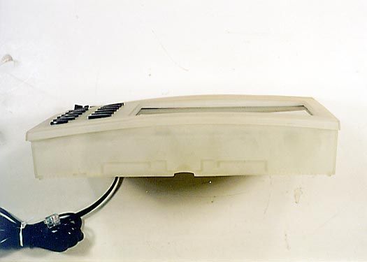
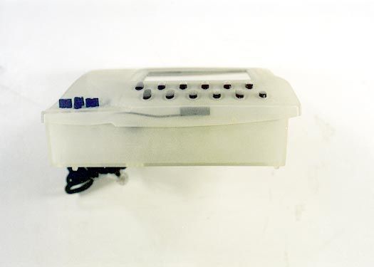
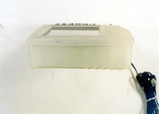
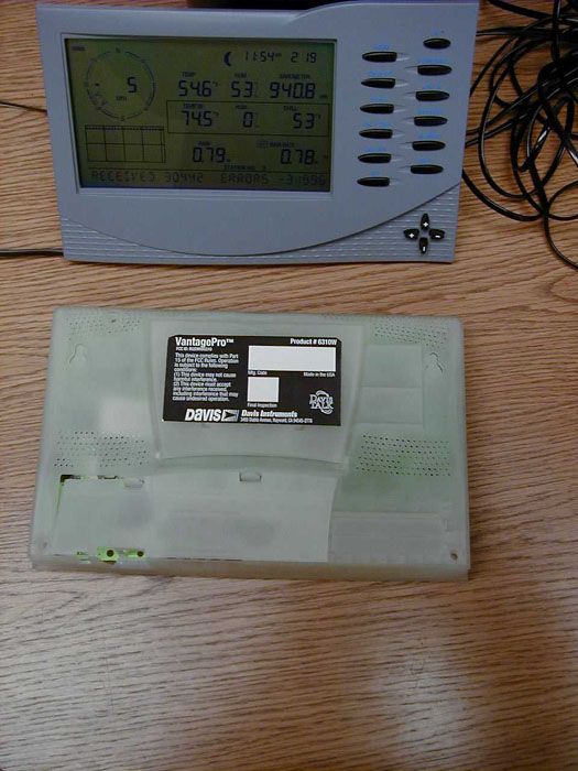
Document Text
Text extracted from the exhibit documents filed with the FCC. Open a document above to read the original.
Users Manual
Vantage Pro Manual Page 1 WE L C O M ET O T H EVA N T A G EPR O5 5 Vantage Pro Formats 5 Display & Keyboard 6 Console Modes 6 Multiple stations / Sensors 7 Optional Sensors 7 Optional Accessories 8 Vantage Pro Console Installation 9 Cabled Vantage Pro Console Installation 10 Powering your Vantage Pro 10 Connecting the Cabled Vantage Pro to the Integrated Sensor Suite (ISS) 10 Wireless Vantage Pro Installation 11 Powering your Wireless Vantage Pro 11 Connecting the Wireless Vantage Pro console to the Integrated Sensor Suite (ISS) 11 Displaying the Vantage Pro Console 11 Table & Shelf Display 12 Wall Display 12 Using the Vantage Pro Console 13 Chapter 3 13 Keyboard 14 Using the Navigation Keys 14 Display Features 15 Setup Mode 18 Current Weather Mode 18 Activating Weather Variables 18 Wind Speed and Direction 18 Temperature 18 Humidity 19 Wind Chill 19 Dew Point 19 Barometric Pressure 20 UV (Ultraviolet Radiation) 20 Vantage Pro Manual Page 2 Heat Indices 21 Rain “Year”, Rain “Month”, and Rain Rate 21 “Daily” and “Storm” Rain 22 Solar Radiation 22 ET (Evapotranspiration) 23 Selecting Units 24 To change the units for any variable: 24 25 Highs and Lows Mode 25 Alarms Mode 26 Graph Mode 27 Troubleshooting 29 Display 30 TEMPERATURE 31 Humidity 31 Wind Speed 32 Direction 32 chill 32 Repair & Warranty information 33 One Year Limited Warranty 33 Questions? Call the Davis Service Center 33 FCC Part 15 Class B Registration Warning 34 Appendix: Weather Data 35 Weather Conditions Measured/Calculated 35 EvapoTranspiration (ETo) 36 Temperature 36 Apparent Temperature Measures 36 Wind 38 Solar Radiation 38 UV (Ultra Violet) Radiation 39 Rainfall 40 Barometric Pressure 40 Relative Humidity 41 Dew-Point & Leaf Wetness 41 Time 42 Vantage Pro Manual Page 3 AutoClear 42 42 Specifications 43 Function 43 Display Reading 43 Accuracy 43 Temperature 43 Welcome to the Vantage Pro 5 Page 4Vantage Pro Console Manual Vantage Pro Manual Page 5 WE L C O M ET O T H EVA N T A G EPR O Welcome to Davis Instruments’ Vantage Pro weather station console. The Van- tage Pro console, part of the comprehensive Vantage Pro system, displays a wealth of weather information -- up to ten weather variables simultaneously. The Vantage Pro console is also a powerful weather computer, collecting, stor- ing, and displaying historical data, including highs and lows, in graphical and numerical formats. The Vantage Pro also provides you with a forecast based on the latest meteoro- logical algorithms. A quick glance at the graphical icons predicts the general weather trend. A detailed forecast scrolls across the bottom of the screen, including predicted xxx <!-- what? his and lows, sunny?, tornados?--!>. Vantage Pro Formats The Vantage Pro System is available in two formats: Cabled and Wireless. • Cabled Vantage Pro System The Cabled Vantage Pro system links the Integrated Sensor Suite (ISS) sensor array to the console with standard four-conductor cable. The Standard Vantage Pro system operates on AC power only. • Wireless Vantage Pro The wireless Vantage Pro console receives data transmitted by radio from the solar-powered ISS. Neither the sensor array, nor the console requires AC power in the wireless format. 1 Page 6Vantage Pro Console Manual Display & Keyboard The Vantage Pro display and keyboard are designed for easy access to the most important weather information. The keyboard allows you to interact with the station computer, view current and historical data, set and clear alarms, change station modes, enter calibra- tion numbers, set up and view graphs, select sensors, read the forecast, and so on. To learn more about the keyboard, see “Keyboard” on page 26. The Large LCD display is your window on current and past environmental conditions, as well as the place to find the forecast. The console LCD can dis- play up to 12 <!--what’s the real number? ticker adds many--!> weather vari- ables at any one time. With the addition of Davis’ programmable weather ticker, a scrolling alphanumeric display, you can completely personalize the display to suit your needs, interests, and curiosities. To learn more about the display’s features, see “Display” on page 21. Console Modes The Vantage Pro console operates in five different modes designed to give you quick and easy access to the information you need: • Setup Setup mode is used to enter the time, date, calibration numbers, and other information required for the processing and display of the weather data. • Current Data Current data is the most common operation mode. In this mode you can read the current weather information and access any weather data not currently displayed using the keyboard. • High / Low The High and Low mode summaries are accessed using the High/Low key. • Alarm Alarm mode allows the user to set, clear, and review alarm settings. • Graph Graph mode allows the user to access the advanced graphing capabili- ties of the Vantage Pro weather computer. For more information about using the console, see “Using the Vantage Pro Console” on page 13 and following sections. Optional Sensors Vantage Pro Manual Page 7 Multiple stations / Sensors The Wireless Vantage Pro system is capable of receiving transmissions from up to eight different transmitters. See “Optional Sensors” below. OP T I O N A LSE N S O R S The Vantage Pro system is extremely flexible. The following optional sensors enable calculation and measurement of specialized weather information. All optional sensors are available from your dealer or may be ordered directly from Davis Instruments. Please be aware that some options are available only- for wireless units. • Solar Radiation Sensor Enables you to measure and display solar irradiance and incident energy. Also required for calculating Evapotranspiration (see “Evapo- Transpiration (ETo)” on page 11). Available for Cabled and Wireless stations. Requires Solar Radiation / UV mounting shelf. See “Optional Accessories” on page 8. • Ultraviolet (UV) Radiation Sensor Enables yo…
Text truncated - open the document above for the full version.
Attestation Statements
Revised Bandwidth Plot The plot contained on page 21 of the CKC Laboratories Test Report FC99-033 does not contain a mask. The plot below is the same plot with the mask included to better illustrate compliance.
Cover Letter(s)
December 7, 1999 Davis Instruments 3465 Diablo Ave. Hayward, CA 94545 Federal Communications Commission 7435 Oakland Mills Road Columbia, MD 21046 Gentlemen: This is your letter of authorization to accept out appointment of CKC Laboratories, Inc. as Agent for Davis Instruments located in Hayward CA to sign applications before the Commission on our behalf, and to receive and exchange data between our company and the commission in connection with certification of the following Davis product: The device we are requesting certification for is our Vantage Pro Console (Product No. 6310W). The device is used in a home or office to display weather data packets from our Integrated Sensor Suite (Product No. 6320W FCC ID: IR2DWW6320) which is installed outside. In addition to displaying the weather data it also can be programmed to retransmit the received packets to other display devices in the home. The transmitter is operating at 916.5 Mhz and uses less than 1 mW or power. Please send the FCC authorization to me, Brett Preston. We, the applicant certify that, in the case of individual applicant, he or she is not subject to a denial of federal benefits pursuant to section 5301 of the Anti-Drug Abuse Act of 1988, 21 USC 853a or in the case of non-individual applicant (e.g. corporation, partnership or other unincorporated association), no party to the applicant is subject to a denial of federal benefit pursuant to that action. This authorization will expire one year from the date of this letter. Sincerely, Brett Preston Director of Engineering
Cover Letter(s)
December 7, 1999 Davis Instruments 3465 Diablo Ave. Hayward, CA 94545 Federal Communications Commission 7435 Oakland Mills Road Columbia, MD 21046 Gentlemen: This letter is to comply with Section 0.457(d)(2)(i) pertaining to confidential material. Davis Instruments would like the following documents regarding this submission for FCC ID: IR2DWW6310 to be kept confidential. 1. "Circuit Diagram.pdf" 2. "Device Summary.doc" The above material contains trade secrets or technical data, which would customarily be guarded from competitors. We do not want these documents to be accessible to the general public. Sincerely, Brett Preston Director of Engineering
ID Label/Location Info
VantagePro ™ Product # 6310W 3465 Diablo Avenue, Hayward, CA 94545-2778 Mfg. Code Made in the USA Final Inspection Size: 4" W x 2 1/4" H Material: Vin yl Location: Can be viewed on the back of the console. This device complies with Part 15 of the FCC Rules. Operation is subject to the following conditions: (1) This device may not cause harmful interference. (2) This device must accept any interference received, including interference that may cause undesired operation. FCC ID: IR2DWW6310
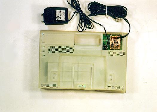
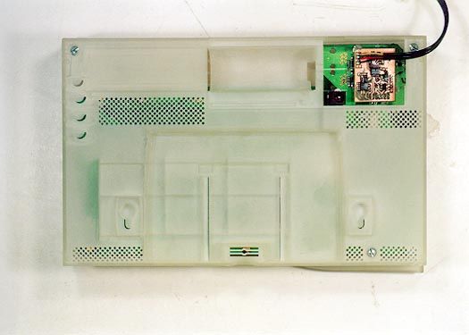
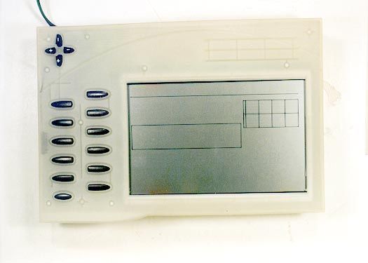
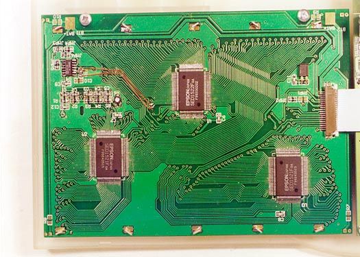
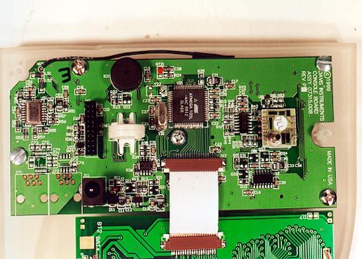
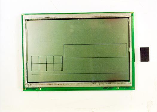
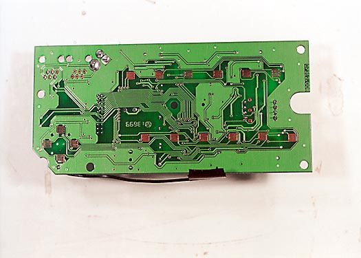
Internal Photos
To: Date:6/28/2009 04:44:16 [email protected] Message: This is notification that this application is approaching the short-term release date of 07/06/2009. If no action is taken, any files marked as short-term confidential will automatically become viewable on the FCC website. Subject: Short-Term Confidentiality Release Notification, Form 731 Confirmation Number: TC184107 FCC ID: NBZNRM-MIFI2352
Test Report
Page 1 of 29 Report No: FC99-033 CERTIFICATION TEST REPORT FOR THE VANTAGE PRO CONSOLE, 6310W FCC PART 15 SUBPART C COMPLIANCE DATE OF ISSUE: DECEMBER 2, 1999 PREPARED FOR: Davis Intruments 3465 Diablo Ave Hayward, CA 94545 P.O. No: W.O. No: 73018 PREPARED BY: Joyce Walker CKC Laboratories, Inc. 5473A Clouds Rest Mariposa, CA 95338 Date of test: November 15-17, 1999 Report No: FC99-033 DOCUMENTATION CONTROL: _____________________________ Tracy Phillips Documentation Control Supervisor CKC Laboratories, Inc. APPROVED BY: _____________________________ Dennis Ward Director of Laboratories CKC Laboratories, Inc. This report contains a total of 29 pages and may be reproduced in full only. Partial reproduction may only be done with the written consent of CKC Laboratories, Inc. Page 2 of 29 Report No: FC99-033 TABLE OF CONTENTS Administrative Information ............................................................................................. 3 Summary Of Results........................................................................................................ 4 Equipment Under Test (EUT) Description...................................................................... 4 Measurement Uncertainty................................................................................................ 4 EUT Operating Frequency............................................................................................... 4 Peripheral Devices ........................................................................................................... 4 Report Of Measurements................................................................................................. 5 Table 1: Fundamental Emission Levels - FCC Part 15.249 ............................... 5 Table 2: Six Highest Radiated Emission Levels ................................................ 6 Table 3: Six Highest Conducted Emission Levels - FCC Part 15.207 ............... 7 Table A: List of Test Equipment ..................................................................................... 8 EUT Setup .......................................................................................................................9 Test Instrumentation And Analyzer Settings................................................................... 10 Table B : Analyzer Bandwidth Settings Per Frequency Range........................... 10 Spectrum Analyzer Detector Functions............................................................... 11 Peak ......................................................................................................... 11 Quasi-Peak............................................................................................... 11 Average.................................................................................................... 11 Test Methods ...................................................................................................................12 Radiated Emissions Testing................................................................................. 12 Conducted Emissions Testing ............................................................................. 13 Transmitter Characteristics.............................................................................................. 13 Occupied Bandwidth ........................................................................................... 13 Sample Calculations ........................................................................................................ 14 Appendix A : Information About The Equipment Under Test........................................ 15 I/O Ports............................................................................................................... 16 Crystal Oscillators ............................................................................................... 16 Printed Circuit Boards ......................................................................................... 16 Cable Information................................................................................................ 16 Required EUT Changes To Comply.................................................................... 16 Photograph Showing Radiated Emissions ........................................................... 17 Photograph Showing Radiated Emissions ........................................................... 18 Photograph Showing Conducted Emissions........................................................ 19 Appendix B : Measurement Data Sheets ......................................................................... 20 Occupied Bandwidth Plot.................................................................................... 21 FCC Part 15.35 Averaging Plot ........................................................................... 22 Page 3 of 29 Report No: FC99-033 CKC Laboratories, Inc. has Certificates of Accreditation from the following agencies : DATech (Germany); A2LA (USA); FCC (USA); VCCI (Japan); BSMI (Taiwan); HOKLAS (Hong Kong). CKC Laboratories, Inc. has Letters of Acceptance through an MRA for the following agencies: ACA/NATA (Australia); SABS (South Africa); SWEDAC (Sweden); TUV Rheinland-Germany; TUV Rheinland- Korea; TUV Rheinland-Russia; Radio Communication Agency (RA); NEMKO (Norway). ADMINISTRATIVE INFORMATION DATE OF TEST: November 15-17, 1999 PURPOSE OF TEST: To demonstrate the compliance of the Vantage Pro Console, 6310W, with the requirements for FCC Part 15 Subpart C devices. MANUFACTURER: Davis Intruments 3465 Diablo Ave Hayward, CA 94545 REPRESENTATIVE: Brett Preston TEST LOCATION: CKC Laboratories, Inc. 5473A Clouds Rest Mariposa, CA 95338 TEST PERSONNEL: D.Oaks TEST METHOD: ANSI C63.4 1992 FREQUENCY RANGE TESTED: 450 kHz – 10 GHz EQUIPMENT UNDER TEST:Weather Station Manuf: Davis Instruments Model: 6310W Serial: N/A FCC ID: IR2DWW6310 (pending) Page 4 of 29 Report No: FC99-033 SUMMARY OF RESULTS The Davis Intrume…
Text truncated - open the document above for the full version.
Contact Information
Applicant
Bruce Walter(Sr Design Engineer)
Technical Contact
CKC Laboratories, Inc.Tracy Phillips
[email protected]1-800-500-4365
5473A Clouds Rest · Mariposa, California · United States
Non-Technical Contact
CKC Laboratories, Inc.Joyce Walker
[email protected]1-800-500-4362
Test Firm
CKC Laboratories, Inc.Steve Behm
Technical Specifications
| # | Rule Parts | Frequency Range | Power Output |
|---|---|---|---|
| 1 | 15C | 916.5 MHz - 916.5 MHz | - |
Other Applications from Davis Instruments
IR2DWW6313U
Jan 03, 2023WeatherLink Console
Equipment Class
DTS - Digital Transmission System
IR2DWW765Y
Jun 09, 2005Vantage Pro 2 Wireless Repeater
Equipment Class
DSS - Part 15 Spread Spectrum Transmitter
IR2DWW6345
Mar 13, 2005Measurement Station
Equipment Class
DSS - Part 15 Spread Spectrum Transmitter
IR2DWW6312
Sep 29, 2004Integrated Vantage Pro 2 Console.
Equipment Class
DSS - Part 15 Spread Spectrum Transmitter
IR2DWW6328
Sep 29, 2004Integrated Sensor Suite 2 with SPARS
Equipment Class
DSS - Part 15 Spread Spectrum Transmitter