IR2DWW765YVantage Pro 2 Wireless Repeater
Davis Instruments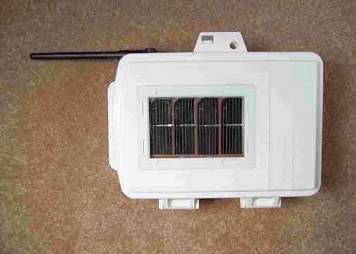
Click to zoom
Application Details
- Equipment Class
- DSS - Part 15 Spread Spectrum Transmitter
- Date of Grant
- Jun 09, 2005
- Application Purpose
- Original Equipment
- Date of Application
- Jun 09, 2005
- Equipment Note
- Vantage Pro 2 Wireless Repeater
- Frequency Range
- 902.00000000 - 928.00000000
- Company
- Davis Instruments
- Country
- United States
Documents & Files
Document Text
Text extracted from the exhibit documents filed with the FCC. Open a document above to read the original.
Users Manual
Long Range Repeater Installation Manual For AC-Powered and Solar-Powered Repeaters Models 7653 and 7654 Vantage Pro2 ™ Long Range Wireless Repeater Manual Rev. A, June 9, 2005 Document Part Number: 07395.258 For Vantage Pro2 Long Range Wireless Repeaters: 7653, 7654 Compatible with Vantage Pro Antennas: 7656, 7660 Vantage Pro ® and Vantage Pro2 ™ are trademarks of Davis Instruments Corp., Hayward, CA. © Davis Instruments Corp. 2005. All rights reserved. Information in this document subject to change without notice. 3465 Diablo Avenue, Hayward, CA 94545-2778 510-732-9229 • Fax: 510-732-9188 E-mail: [email protected] • www.davisnet.com FCC Part 15 Class B Registration Warning This equipment has been tested and found to comply with the limits for a Class B digital device, pursuant to Part 15 of the FCC Rules. These limits are designed to provide reasonable protection against harmful interference in a res- idential installation. This equipment generates, uses, and can radiate radio frequency energy and, if not installed and used in accordance with the instructions, may cause harmful interference to radio communications. However, there is no guarantee that interference will not occur in a particular installation. If this equipment does cause harmful interference to radio or television reception, which can be determined by turning the equipment on and off, the user is encouraged to try to correct the interference by one or more of the following measures: •Reorient or relocate the receiving antenna. •Increase the separation between the equipment and receiver. •Connect the equipment into an outlet on a circuit different from that to which the receiver is connected. •Consult the dealer or an experienced radio/TV technician for help. Changes or modification not expressly approved in writing by Davis Instruments may void the warranty and void the user's authority to operate this equipment. FCC ID: IRDWW765Y IC: 3788A-765Y EC EMC Compliance This product complies with the essential protection requirements of the EC EMC Directive 89/336/EC, as tested to the following directives: •ETSI EN 300 220 •ETSI EN 301 489 This device has been designed to operate with an antenna having a maximum gain of 11 dBi. Antennas having a higher gain are strictly prohibited per regulations of Industry Canada. The required antenna impedance is 50 ohms. To reduce potential radio interference to other users, the antenna type and its gain should be chosen that the equiv- alent isotropically radiated power (EIRP) is not more than that required for successful communication. 1 Welcome! The Vantage Pro2 ™ Long Range Repeater can be used with any Vantage Pro2 wireless transmitter station and re-transmits the information to a Vantage Pro2 compatible receiver (Vantage Pro2 console or Envoy ® ). The Long Range Repeater works in much the same way as the Vantage Pro2 wireless repeaters, but extends the range and distance between a repeater and a receiver by up to 10 times that of the Vantage Pro2 wireless repeater. Long Repeater Manual Overview This manual provides additions information specific to the installation and use of the Long Range Repeaters and is intended to be used in conujunction with the Wireless Repeater Installation Manual. The table below shos the location of the information required to install and maintain your Long Range Repeaters: Section/ProcedureIn This Manual In the Wireless Repeater Manual Components and HardwareX Additional Antenna Components and HardwareX Repeater Board ContentsXX Tools for SetupX Wireless Repeater IntroductionX Repeater Configurations/ArchitectureX Applying PowerX Single Repeater InstallationX Advanced Repeater InstallationX Mounting the Long Range Wireless Repeater and Antennas X Connecting External Antennas to the RepeaterX Console and WeatherLink ConfigurationX Long Range Repeater TroubleshootingX Long Range Repeater SpecificationX 2 Long Range Repeater Components and Hardware In addition to the wireless repeater enclosure and hardware, the long range repeater comes equipped with custom-selected external antennas that can be used separately on in comibination of one another. Omni-direction Antenna Yagi Antenna Omni Antenna 5/16" U-Bolts 48" Antenna Cable Flat Washer Lock Washer Nut Yagi Antenna 5/16" U-Bolts 48" Antenna Cable Flat Washer Lock Washer Nut 3 Repeater Board Contents The board contained within the repeater enclosure has the following contents: Transmitter DIP Switches Repeater DIP Switches Repeater Test Switch TX LED Status LED Battery Compartment Solar Power Tab AC AdpaterRepeater Cables 4 The component unique to the Long Range Repeater board is: •Antenna Cables — Connects the repeater board to the external antennas. Mounting the Wireless Repeater The antenna configuration and wireless repeater can be mounted on a pole at designated location. Use the brovided U-bolts for the wireless repeater and the U-bolts provided for each antenna type to install them all to a pole. . Installing a Repeater\Antenna(s) on a Pole Refer to the following illustrations to install the repeater and antennas on a pole: 1. Place the repeater enclosure at a low place on the pole to provide enough room on the top of the pole to mount the necessary antennas. 2. While holding the shelter against the pole close to the bottom, place a U-bolt around the pole and through the two holes on at the top of the shelter. 3. Place a flat washer, a lock washer and a hex nut on each of the bolt ends. 4. Using an adjustable wrench or 7/16" wrench, tighten the nuts. 5. Place the second U-bolt around the pole and through the two holes at the bottom of the shelter. 6. Put a flat washer, a lock washer, and a hex nut on each bolt end, and tighten the hex nuts. Depending on the types of antennas selected, use the illustrations on the follow- ing pages to assemble and mount your selected antennas: Flat Washer Lock Washer Hex Nut U-Bolt 5 Omni and Yagi Antenna Combination Assembly Omni Antenna Yagi Antenna 5/16" U-Bolts Flat W…
Text truncated - open the document above for the full version.
Users Manual
Wireless Repeater Installation Manual For AC-Powered and Solar-Powered Repeaters Models 7626 and 7627 Vantage Pro2 ™ Wireless Repeater Manual Rev. A, June 2, 2005 Document Part Number: 07395.238 For Vantage Pro2 Wireless Repeaters: 7626, 7627 Vantage Pro ® and Vantage Pro2 ™ are trademarks of Davis Instruments Corp., Hayward, CA. © Davis Instruments Corp. 2005. All rights reserved. Information in this document subject to change without notice. 3465 Diablo Avenue, Hayward, CA 94545-2778 510-732-9229 • Fax: 510-732-9188 E-mail: [email protected] • www.davisnet.com FCC Part 15 Class B Registration Warning This equipment has been tested and found to comply with the limits for a Class B digital device, pursuant to Part 15 of the FCC Rules. These limits are designed to provide reasonable protection against harmful interference in a residential installation. This equipment generates, uses, and can radiate radio frequency energy and, if not installed and used in accordance with the instructions, may cause harmful interference to radio communications. However, there is no guarantee that interference will not occur in a particular installation. If this equipment does cause harmful interference to radio or television reception, which can be determined by turning the equipment on and off, the user is encour- aged to try to correct the interference by one or more of the following measures: •Reorient or relocate the receiving antenna. •Increase the separation between the equipment and receiver. •Connect the equipment into an outlet on a circuit different from that to which the receiver is connected. •Consult the dealer or an experienced radio/TV technician for help. Changes or modification not expressly approved in writing by Davis Instruments may void the warranty and void the user's authority to operate this equipment. FCC ID: IR2DWW765Y IC: 3788A-765Y EC EMC Compliance This product complies with the essential protection requirements of the EC EMC Directive 89/336/EC, as tested to the follow- ing directives: •ETSI EN 300 220 •ETSI EN 301 489 Transmitter and Repeater ID Worksheet Circle all the transmitter and repeater IDs used in your network: Transmitter TypeTransmitter IDRepeater ID 1A 2B 3C 4D 5E 6F 7G 8H i Table of Contents Introduction ......................................................................................................... 1 Included Components and Hardware .............................................................. 1 Wireless Repeater Installation Overview........................................................ 2 Applying Battery Power.................................................................................. 2 Repeater Configuration/Architecture .................................................................. 4 Repeater Architecture..................................................................................... 4 Single Repeater Configuration........................................................................ 4 Advanced Repeater Configurations ................................................................ 5 Single Repeater Installation................................................................................. 8 Verify Transmitter ID ..................................................................................... 8 Verifying Communication with a Transmitter................................................ 9 Choosing a Location ..................................................................................... 11 Testing a Proposed Location......................................................................... 12 Advanced Repeater Installation......................................................................... 13 Multiple Repeater (Daisy-Chain) Installation............................................... 13 Multiple Transmitters, One Repeater Installation......................................... 15 Combination Network Installation................................................................ 17 Choosing Locations....................................................................................... 19 Testing Proposed Locations .......................................................................... 19 Mounting the Wireless Repeater ....................................................................... 20 General Installation Guidelines..................................................................... 20 Installing the Repeater on a Flat Surface ...................................................... 20 Installing the Repeater on a Pole................................................................... 21 WeatherLink and Console Configuration.......................................................... 22 Repeater Information on the Console ........................................................... 22 Repeater Functionality in WeatherLink ........................................................ 23 Maintenance and Troubleshooting .................................................................... 25 Communication Troubleshooting ................................................................. 25 Repeater Troubleshooting Error Codes......................................................... 25 Repeater Maintenance................................................................................... 27 Appendix A ....................................................................................................... 28 Specifications ................................................................................................ 28 Repeater Board Display and Contents .......................................................... 29 1 Introduction The Vantage Pro2 ™ Wireless Repeater can be used with any Vantage Pro2 wireless trans- mitter station and re-transmits the information to a Vantage Pro2 compatible receiver (Vantage Pro2 console or Envoy ® ). Note: Not all consoles have the capability to access wireless repeater information. If your c…
Text truncated - open the document above for the full version.
Cover Letter(s)
Response to E05-000177-1 and E05-000177-1 IC E05-000177-1 1 & 2. The test report has been revised to make the required changes. E05-000177-1 IC 1. Ok. 2, 3 & 4. A revised users manual has been uploaded. 5. The requested information has been added to page 19 of the test report.
External Photos
Front Back Top Bottom Left Right
Internal Photos
Interior Overall Interior Overall Removeable Antenna Version PCB Top PCB Bottom
Operational Description
Expository Statement Equipment Name: Vantage Pro 2 Repeater Model Number: 7653, 7654 7653 is the AC powered version 7654 is the solar powered version. Description: The 7654 is a repeater for use with the Vantage Pro 2 system. It transmits/receives information every 2.5 seconds using Frequency Hopping Spread Spectrum technology with Frequency Shift Keying the carrier at 19200 baud rate. It hops it though 51 channels using a pseudo-random hop table though the 902-928 MHz band. It can repeater up to 8 different Vantage Pro 2 station. These stations are selected though a series of DIP switches that the user selects once. The unit can be either solar powered with a battery back up or powered through a 5 volt DC wall adapter with battery back up. Circuitry: The 7654 and 7653 contains 1 circuit boards, this circuit board is housed in a plastic enclosure that measures 8 x 6 x 3 inches. Antenna: The antenna can be either a Yagi with a gain of 11 dBi or a Omni with a gain of 5 dBi this connects to the PCBa via a Reverse TNC connector. Model Number: 7626, 7627 7626 is the AC powered version 7627 is the solar powered version Description: The 7626 is a repeater for use with the Vantage Pro 2 system. It transmits/receives information every 2.5 seconds using Frequency Hopping Spread Spectrum technology with Frequency Shift Keying the carrier at 19200 baud rate. It hops it though 51 channels using a pseudo-random hop table though the 902-928 MHz band. It can repeater up to 8 different Vantage Pro 2 station. These stations are selected though a series of DIP switches that the user selects once. The unit can be either solar powered with a battery back up or powered through a 5 volt DC wall adapter with battery back up. Circuitry: The 7626 and 7626 contains 1 circuit boards, this circuit board is housed in a plastic enclosure that measures 8 x 6 x 3 inches. Antenna: The antenna is a 5 inch Dipole that is integrated to the PCBa
Test Report
Page 1 of 68 Report No: FC05-023 DAVIS INSTRUMENTS TEST REPORT FOR THE VANTAGE PRO 2 WIRELESS REPEATER, 7626, 7627, 7653 & 7654 FCC PART 15 SUBPART C SECTIONS 15.207, 15.209, 15.247, SUBPART B SECTION 15.109 CLASS B AND RSS-210 COMPLIANCE DATE OF ISSUE: JUNE 1, 2005 PREPARED FOR: Davis Instruments 3465 Diablo Avenue Hayward, CA 94545 PREPARED BY: Mary Ellen Clayton CKC Laboratories, Inc. 5046 Sierra Pines Drive Mariposa, CA 95338 P.O. No.: W.O. No.: 59029 83394 Date of test: May 5-27, 2005 Report No.: FC05-023 This report contains a total of 68 pages and may be reproduced in full only. Partial reproduction may only be done with the written consent of CKC Laboratories, Inc. The results in this report apply only to the items tested, as identified herein. Page 2 of 68 Report No: FC05-023 TABLE OF CONTENTS Administrative Information .............................................................................................4 FCC to Canada Standard Correlation Matrix...................................................................5 Conditions for Compliance ..............................................................................................5 Approvals .........................................................................................................................5 FCC 15.31(e) Voltage Variation......................................................................................6 FCC 15.31(m) Number Of Channels ...............................................................................6 FCC 15.33(a) Frequency Ranges Tested .........................................................................6 FCC 15.35 Analyzer Bandwidth Settings ........................................................................6 FCC 15.203 Antenna Requirements ................................................................................6 Eut Operating Frequency .................................................................................................6 Equipment Under Test (EUT) Description ......................................................................7 Equipment Under Test .....................................................................................................7 Peripheral Devices ...........................................................................................................7 Report of Measurements ..................................................................................................8 Table 1: FCC 15.109 Six Highest Radiated Emission Levels .............................8 Table 2: FCC 15.111 Six Highest Radiated Emission Levels .............................9 Table 3: FCC 15.207 Six Highest Conducted Emission Levels ..........................10 FCC 15.247(a) Average Time Of Occupancy .....................................................11 FCC 15.247(a)(1) Frequency Separation .............................................................12 FCC 15.247(a)(1) Number Of Hopping Channels...............................................13 FCC 15.247(a)(1) Dwell Time Per Hop Time .....................................................14 FCC 15.247(a)/RSS-210 Occupied Bandwidth ...................................................15 Table 4: FCC 15.247(b)(2) Fundamental Emission Levels .................................18 Table 5: FCC 15.247(b)(3) Six Highest Radiated Emission Levels ....................19 Table 6: FCC 15.247(c)/15.209 Six Highest OATS Radiated Emission Levels .20 Table 7: FCC 15.247(c) Six Highest Antenna Conducted Emission Levels .......21 FCC 15.247(c) Band Edge ...................................................................................22 Temperature And Humidity During Testing....................................................................30 EUT Setup........................................................................................................................30 Correction Factors............................................................................................................30 Table A: Sample Calculations .............................................................................30 Test Instrumentation and Analyzer Settings ....................................................................31 Spectrum Analyzer Detector Functions ...............................................................31 Peak..........................................................................................................31 Quasi-Peak ...............................................................................................31 Average ....................................................................................................31 EUT Testing.....................................................................................................................32 Mains Conducted Emissions................................................................................32 Antenna Conducted Emissions ............................................................................32 Radiated Emissions ..............................................................................................32 Appendix A: Test Setup Photographs..............................................................................34 Photograph Showing Radiated Emissions ...........................................................35 Page 3 of 68 Report No: FC05-023 Photograph Showing Radiated Emissions ...........................................................36 Photograph Showing Radiated Emissions ...........................................................37 Photograph Showing Radiated Emissions ...........................................................38 Photograph Showing Mains Conducted Emissions .............................................39 Photograph Showing Direct Connect Test Setup.................................................40 Photograph Showing Direct Connect Test Setup.................................................41 Appendix …
Text truncated - open the document above for the full version.
Test Report
Page 1 of 68 Report No: FC05-023A ADDENDUM TO DAVIS INSTRUMENTS TEST REPORT FC05-023 FOR THE VANTAGE PRO 2 WIRELESS REPEATER, 7626, 7627, 7653 & 7654 FCC PART 15 SUBPART C SECTIONS 15.207, 15.209, 15.247, SUBPART B SECTION 15.109 CLASS B AND RSS-210 COMPLIANCE DATE OF ISSUE: JUNE 1, 2005 PREPARED FOR: Davis Instruments 3465 Diablo Avenue Hayward, CA 94545 PREPARED BY: Mary Ellen Clayton CKC Laboratories, Inc. 5046 Sierra Pines Drive Mariposa, CA 95338 P.O. No.: W.O. No.: 59029 83394 Date of test: May 5-27, 2005 Report No.: FC05-023A This report contains a total of 68 pages and may be reproduced in full only. Partial reproduction may only be done with the written consent of CKC Laboratories, Inc. The results in this report apply only to the items tested, as identified herein. Page 2 of 68 Report No: FC05-023A TABLE OF CONTENTS Administrative Information .............................................................................................4 FCC to Canada Standard Correlation Matrix...................................................................5 Conditions for Compliance ..............................................................................................5 Approvals .........................................................................................................................5 FCC 15.31(e) Voltage Variation......................................................................................6 FCC 15.31(m) Number Of Channels ...............................................................................6 FCC 15.33(a) Frequency Ranges Tested .........................................................................6 FCC 15.35 Analyzer Bandwidth Settings ........................................................................6 FCC 15.203 Antenna Requirements ................................................................................6 Eut Operating Frequency .................................................................................................6 Equipment Under Test (EUT) Description ......................................................................7 Equipment Under Test .....................................................................................................7 Peripheral Devices ...........................................................................................................7 Report of Measurements ..................................................................................................8 Table 1: FCC 15.109 Six Highest Radiated Emission Levels .............................8 Table 2: FCC 15.111 Six Highest Radiated Emission Levels .............................9 Table 3: FCC 15.207 Six Highest Conducted Emission Levels ..........................10 FCC 15.247(a) Average Time Of Occupancy .....................................................11 FCC 15.247(a)(1) Frequency Separation .............................................................12 FCC 15.247(a)(1) Number Of Hopping Channels...............................................13 FCC 15.247(a)(1) Dwell Time Per Hop Time .....................................................14 FCC 15.247(a)/RSS-210 Occupied Bandwidth ...................................................15 Table 4: FCC 15.247(b)(2) Fundamental Emission Levels .................................18 Table 5: FCC 15.247(b)(3) Six Highest Radiated Emission Levels ....................19 Table 6: FCC 15.247(c)/15.209 Six Highest OATS Radiated Emission Levels .20 Table 7: FCC 15.247(c) Six Highest Antenna Conducted Emission Levels .......21 FCC 15.247(c) Band Edge ...................................................................................22 Temperature And Humidity During Testing....................................................................30 EUT Setup........................................................................................................................30 Correction Factors............................................................................................................30 Table A: Sample Calculations .............................................................................30 Test Instrumentation and Analyzer Settings ....................................................................31 Spectrum Analyzer Detector Functions ...............................................................31 Peak..........................................................................................................31 Quasi-Peak ...............................................................................................31 Average ....................................................................................................31 EUT Testing.....................................................................................................................32 Mains Conducted Emissions................................................................................32 Antenna Conducted Emissions ............................................................................32 Radiated Emissions ..............................................................................................32 Appendix A: Test Setup Photographs..............................................................................34 Photograph Showing Radiated Emissions ...........................................................35 Page 3 of 68 Report No: FC05-023A Photograph Showing Radiated Emissions ...........................................................36 Photograph Showing Radiated Emissions ...........................................................37 Photograph Showing Radiated Emissions ...........................................................38 Photograph Showing Mains Conducted Emissions .............................................39 Photograph Showing Direct Connect Test Setup.................................................40 Photograph Showing Direct Connect Test Setup....................................…
Text truncated - open the document above for the full version.
Test Setup Photos
PHOTOGRAPH SHOWING RADIATED EMISSIONS Radiated Emissions - Front View PHOTOGRAPH SHOWING RADIATED EMISSIONS Omni Antenna PHOTOGRAPH SHOWING RADIATED EMISSIONS Yagi Antenna PHOTOGRAPH SHOWING RADIATED EMISSIONS Radiated Emissions - Receiver PHOTOGRAPH SHOWING MAINS CONDUCTED EMISSIONS Mains Conducted Emissions - Front View PHOTOGRAPH SHOWING DIRECT CONNECT TEST SETUP Transmitter PHOTOGRAPH SHOWING DIRECT CONNECT TEST SETUP Receiver
Contact Information
Applicant
Bruce Walter(Sr Design Engineer)
Technical Contact
CKC Laboratories, Inc.Mary Ellen Clayton
[email protected]800-500-4362
5046 Sierra Pines Drive · Mariposa, California · United States
Test Firm
CKC Laboratories, Inc.Steve Behm
Technical Specifications
| # | Rule Parts | Frequency Range | Power Output |
|---|---|---|---|
| 1 | 15C | 902 MHz - 928 MHz | 3.50 mW |
Other Applications from Davis Instruments
IR2DWW6313U
Jan 03, 2023WeatherLink Console
Equipment Class
DTS - Digital Transmission System
IR2DWW6345
Mar 13, 2005Measurement Station
Equipment Class
DSS - Part 15 Spread Spectrum Transmitter
IR2DWW6312
Sep 29, 2004Integrated Vantage Pro 2 Console.
Equipment Class
DSS - Part 15 Spread Spectrum Transmitter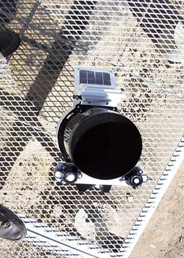
IR2DWW6328
Sep 29, 2004Integrated Sensor Suite 2 with SPARS
Equipment Class
DSS - Part 15 Spread Spectrum Transmitter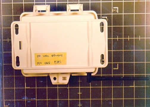
IR2DWW6361
Aug 19, 2001Soil Moisture Station, 6361
Equipment Class
DXX - Part 15 Low Power Communication Device Transmitter