IR2DWW6345Measurement Station
Davis Instruments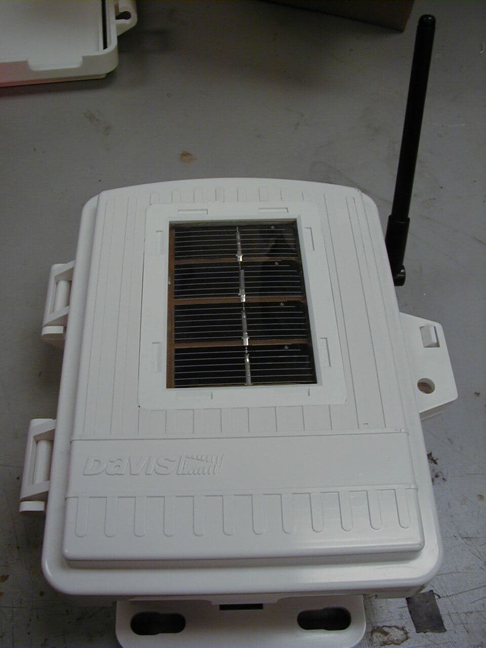
Click to zoom
Application Details
- Equipment Class
- DSS - Part 15 Spread Spectrum Transmitter
- Date of Grant
- Mar 13, 2005
- Application Purpose
- Original Equipment
- Date of Application
- Mar 13, 2005
- Equipment Note
- Measurement Station
- Frequency Range
- 902.35597500 - 927.44347500
- Company
- Davis Instruments
- Country
- United States
Documents & Files
Document Text
Text extracted from the exhibit documents filed with the FCC. Open a document above to read the original.
Users Manual
1 Wireless Leaf & Soil Moisture/Temperature Station Installation Manual For Wireless Vantage Pro2 ™ and Vantage Pro2 Plus ™ The Wireless Leaf & Soil Moisture/Temperature Station (referred to in this document as the Leaf/Soil Station) can be used with any Wireless Vantage Pro2 weather station to measure leaf wetness, soil moisture, or temperature. The following Vantage Pro2 console station configurations can be used with the Leaf/Soil Station: • Only one Leaf/Soil Station can be installed as a Leaf/Soil Station per Vantage Pro2 Weather Station. • Two stations can be installed if one is configured as a Leaf Station and the other station is configured as a Soil Station in the Vantage Pro2 console. • Configured as a Leaf Station, the Station supports two leaf wetness sensors and two temperature probes. • Configured as a Soil Station, it supports up to four soil moisture sensors and tem- perature probes. Note: In any station using soil moisture sensors, the corresponding temperature probe, if installed, will be used for temperature compensation of the soil moisture sensor. Tools for Setup In addition to the components shown, you will need some or all of the following materials: • Adjustable wrench or 7/16" wrench • Medium Phillips Screwdriver • Ballpoint pen or paper clip (small pointed object of some kind) • Drill and 3/16" (5 mm) drill bit (if mounting on a vertical surface) • Stepped Sensor Installation Tool for Soil Moisture and Temperature Sensors (rec- ommended, see page 16) Station Type in Console Configuration Number of Leaf Wetness Sensors Number of Soil Moisture Sensors Number of Temp Probes LEAF/SOIL Station244 LEAF Station2-2 SOIL Station-44 07395.267 Manual Leaf and Soil Moisture Temp Station 2.fm Page 1 Friday, February 4, 2005 5:50 PM 2 Components The Leaf/Soil Station includes the following components and hardware: Optional Sensors The following optional sensors are available for the Leaf/Soil Station: Shelter 3-Volt Lithium Battery 8" Cable Ties 4" Cable Ties 1/4" x 1-1/2" Lag Screws U-Bolts 1/4" Flat Washers 1/4" Lock Washers 1/4" Hex Nuts Leaf/Soil Station Components #8 Wood Screws U-Bolts 1/4" Flat Washers 1/4" Hex Nuts Leaf Wetness Sensor with 40' (12.2 m) of cable #8 x 3/4" Machine Screws #8 Hex Nuts #8 Lock Washers #8 Flat Washers Optional Leaf Wetness Sensor (#6420) Soil Moisture Sensor with 15' (4.6 m) of cable Temperature Probe with 15' (4.6 m) of cable Optional Soil Moisture Sensor (#6440) and Optional Temperature Sensor (#6470) 07395.267 Manual Leaf and Soil Moisture Temp Station 2.fm Page 2 Friday, February 4, 2005 5:50 PM 3 Installation Steps For ease of installation and use of your Leaf/Soil Station, please follow steps in the order presented. • Preparing the station, page 3 • Setting the transmitter ID, page 5 • Choosing a location to mount the station, page 8 • Mounting the station, page 9 • Rules for using the sensors, page 10 • Installing leaf wetness sensors, page 11 • Installing soil moisture and temperature sensors, page 13 • Using soil moisture readings, page 17 If you encounter difficulties or have questions about your station, the following additional information may be helpful: • Troubleshooting the sensors, page 18 • Extending Sensor Cables, page 18 • Contacting Davis Technical Support, page 19 • Specifications, page 19 • FCC Warning, page 20 Preparing the Leaf/Soil Station The following illustrations show the location of the transmitter ID DIP switches, the battery mounting location, the modular connectors used by the leaf wetness sensors, and the terminal blocks used to connect the soil moisture sensors and temperature probes. 07395.267 Manual Leaf and Soil Moisture Temp Station 2.fm Page 3 Friday, February 4, 2005 5:50 PM 4 Installing the Battery 1. Insert the 3-volt lithium battery into the battery holder, matching the “+” sign on the battery with the “+” sign next to the battery mounting brackets. 2. Note the location of the DIP switches. You will work with them during the next installation step. Temporarily Connecting a Sensor for Testing Temporarily connect at least one of the following sensors. Note: You must have at least one sensor installed in the Leaf/Soil station in order to test wireless com- munications. Leaf Wetness Sensor Connection • Connect the leaf wetness sensor cable to the LEAF 1 or LEAF 2 receptacle by plugging it in the proper receptacle. Soil Moisture Sensor Connection Temporarily connect a soil moisture probe to the SOIL 1 terminal block connector using the following instruc- tions. 1. Use a pen or small screwdriver to open the connector “jaws” as shown in the illustration at the top of the next page. 2. While the jaws are open, insert the temperature probe leads, then let the connec- tor jaws close in on the lead by removing the pen or small screwdriver. Note: The soil moisture sensor must be moist to be used for this test. A completely dry sensor will not register on the console. 3-Volt Lithium Battery DIP Switch es Cable Clamp Mount Leaf Wetness Sensor Cable Rubber Grommets SENSORSENSOR INTERFACEINTERFACE MODULEMODULE + - Cable Clamp Test LED Cable Clamp Screw TemperatureMoisture 1 2 3 4 1 2 3 4 Soil Moisture Sensor Cable Temperature Probe Cable Connecting a Leaf Wetness Sensor 07395.267 Manual Leaf and Soil Moisture Temp Station 2.fm Page 4 Friday, February 4, 2005 5:50 PM 5 Soil Temperature Sensor Connection Temporarily connect a temperature probe to the TEMP 1 terminal block connector. 1. Use a pen or small screwdriver to open the connector “jaws” as shown in the illustration to the right. 2. While the jaws are open, insert the temperature probe leads, then let the connector jaws close in on the lead by removing the pen or small screw- driver. Setting the Transmitter ID Each wireless transmitting station must be set to one of eight transmitter IDs. DIP switches #1, 2 and 3 on the Sensor Interface Module (SIM) allow you to control the ID — the “channel” the station will transmit on. (DIP switch #4 is used for trans- mi…
Text truncated - open the document above for the full version.
Cover Letter(s)
March 2 nd , 2005 In response to your comments dated February 17 th , 2005 regarding the application for FCC ID: IR2DWW6345, please find our responses below: 1) System receivers shall have input bandwidths that match the hopping channel bandwidths of their corresponding transmitters and shall shift frequencies in synchronization with the transmitted signals (15.247(a)(1)). Please provide information that shows this device complies with this. The device is a transmit-only device. It is used with a transceiver (FCC IR2DWW6312) that has the same channel spacing and that meets the input bandwidth requirements of 15.247 (a)(1). 2) This device shall use a pseudo-randomly ordered list of hopping frequencies. Please explain how this device accomplishes this and also provide sample hopping tables (minimum of 2 if the device is capable of having multiple hopping tables. The Operational Description has been updated with the hopping table (there is only one). 3) Please provide information showing compliance with 15.247(g)/(h). The Operational Description has been updated to explain that the device hops through the hopset without deviation and does not incorporate any intelligence to synchronize its hopset with other devices. The device will hop through the entire table continuously until powered off. When first powered on it starts at the first frequency in the hop table, but as this reset will occur infrequently, on average all channels are used equally. 4) The test report mentions a normal transmission only occurs every 2.5 seconds. Please provide theory of operation to confirm worse case timing and design of the system. Note the test report mentions 7.5 ms TX period per channel. The Operational Description has been updated to describe the 7.5ms transmission on a channel every 2.5 seconds, with plots attached. 5) The averaging duty factor is states as 7.5 ms TX period, however other test data (equal use on the average) shows the device can transmit up to 465 mS per hop. This would not allow any duty cycle correction and would cause many of the results show to be in excess of the limits for average emissions. Please explain/correct as necessary. Additionally, it is expected that the worse case theory support the measurements as well. For FCC test purposes the device was configured to transmit in a hopping mode at a faster rate that the actual once every 2.5 seconds and for longer than the actual 7.5ms per transmission period to allow the channels to be easily identified. The channel occupancy data has been removed form the test report and replaced by plots and more detailed information in the revised Operational Description. 6) Please include a tunable list of frequencies. The user manual appears to state only 8 channels are used but this appears different in the report. The ID refers to codes that are used to identify a particular sensor station and that the ID code should not be confused with the number of channels, which is 51. 7) It appears from the users manual (page 5) that the device uses only one channel at a time. If so, how is this considered to be FH? Again IDs and Channels are being confused – the device will always hop through all 51 channels. 8) How does the test mode comply with the FHSS requirements? The test mode described in the user’s manual enables an LED to flash whenever the device transmits. The device continues to transmit in its usual hopping mode during the “test mode”. Hopefully the more recent version of the user manual (uploaded to the TCB website) will also help to clarify this. 9) Please consider adding a statement to the users manual to explain to the user that the device has been evaluated to meet the FCC RF exposure requirements. Davis Instruments will consider adding the statement on the next revision of the manual. The following documents have been uploaded to the ATCB website to support the responses above: • 07395.267 Manual Leaf and Soil Moisture Temp Station Manual revised.pdf • Expository Statement revised.doc • R58565 Revised.pdf Regards, Mark Briggs
Cover Letter(s)
American Telecommunications Certification Body Inc. 6731 Whittier Ave, McLean, VA 22101 February 16, 2005 RE: Davis Instruments, Corp. FCC ID: IR2DWW6345 After a review of the submitted information, I have a few comments on the above referenced Application. 1) System receivers shall have input bandwidths that match the hopping channel bandwidths of their corresponding transmitters and shall shift frequencies in synchronization with the transmitted signals (15.247(a)(1)). Please provide information that shows this device complies with this. 2) This device shall use a pseudorandomly ordered list of hopping frequencies. Please explain how this device accomplishes this and also provide sample hopping tables (minimum of 2 if the device is capable of having multiple hopping tables. 3) Please provide information showing compliance with 15.247(g)/(h). 4) The test report mentions a normal transmission only occurs every 2.5 seconds. Please provide theory of operation to confirm worse case timing and design of the system. Note the test report mentions 7.5 ms TX period per channel. 5) The averaging duty factor is states as 7.5 ms TX period, however other test data (equal use on the average) shows the device can transmit up to 465 mS per hop. This would not allow any duty cycle correction and would cause many of the results show to be in excess of the limits for average emissions. Please explain/correct as necessary. Additionally, it is expected that the worse case theory support the measurements as well. 6) Please include a tunable list of frequencies. The user manual appears to state only 8 channels are used but this appears different in the report. 7) It appears from the users manual (page 5) that the device uses only one channel at a time. If so, how is this considered to be FH? 8) How does the test mode comply with the FHSS requirements. 9) Please consider adding a statement to the users manual to explain to the user that the device has been evaluated to meet the FCC RF exposure requirements. Timothy R. Johnson Examining Engineer mailto: [email protected] The items indicated above must be submitted before processing can continue on the above referenced application. Failure to provide the requested information may result in application termination. Correspondence should be considered part of the permanent submission and may be viewed from the Internet after a Grant of Equipment Authorization is issued. Please do not respond to this correspondence using the email reply button. In order for your response to be processed expeditiously, you must submit your documents through the AmericanTCB.com website. Also, please note that partial responses increase processing time and should not be submitted. Any questions about the content of this correspondence should be directed to the sender. z Page 2 February 18, 2005
RF Exposure Info
MPE Calculations Although this device is not portable, it meets the requirements for portable devices that may be used at separation distances of less than 2.5cm from the human body because its output power is below the threshold of 60/fGHz mW (approximately 65mW for a 928MHz device). As the MPE is 0.002 mW/cm 2 , which is less than 5% of the exposure limit, no co- location warnings are required.
Test Report
File: R58565 Page 1 of 18 Electromagnetic Emissions Test Report and Application for Grant of Equipment Authorization pursuant to FCC Part 15, Subpart C (15.247) FHSS Specifications and Industry Canada RSS 210 Issue 5 for an Intentional Radiator on the Davis Instruments Corp. Model: 6345 Wireless Leaf and Soil Moisture/Temperature Station FCC ID: IR2DWW6345 UPN: 3788A-6345 GRANTEE: Davis Instruments Corp. 3465 Diablo Ave. Hayward, CA 94545 TEST SITE: Elliott Laboratories, Inc. 684 W. Maude Avenue Sunnyvale, CA 94086 REPORT DATE: January 31, 2005 FINAL TEST DATE: January 18, 2005 AUTHORIZED SIGNATORY: ______________________________ David W. Bare Chief Technical Officer Elliott Laboratories, Inc. is accredited by the A2LA, certificate number 2016-01, to perform the test(s) listed in this report. This report shall not be reproduced, except in its entirety, without the written approval of Elliott Laboratories, Inc. 2016-01 Elliott Laboratories, Inc. -- EMC Department Test Report Report Date: January 31, 2005 File: R58565 Page 2 of 18 pages TABLE OF CONTENTS COVER PAGE...................................................................................................................................................................................1 TABLE OF CONTENTS..............................................................................................................................................................2 SCOPE............................................................................................................................................................................................4 OBJECTIVE...................................................................................................................................................................................4 SUMMARY OF RESULTS...........................................................................................................................................................5 MEASUREMENT UNCERTAINTIES....................................................................................................................................6 EQUIPMENT UNDER TEST (EUT) DETAILS..........................................................................................................................7 GENERAL...................................................................................................................................................................................7 OTHER EUT DETAILS.............................................................................................................................................................7 ENCLOSURE..............................................................................................................................................................................7 MODIFICATIONS.....................................................................................................................................................................7 SUPPORT EQUIPMENT...........................................................................................................................................................8 EUT INTERFACE PORTS........................................................................................................................................................8 EUT OPERATION.....................................................................................................................................................................8 ANTENNA REQUIREMENTS.................................................................................................................................................8 TEST SITE......................................................................................................................................................................................9 GENERAL INFORMATION.....................................................................................................................................................9 CONDUCTED EMISSIONS CONSIDERATIONS.................................................................................................................9 RADIATED EMISSIONS CONSIDERATIONS....................................................................................................................9 MEASUREMENT INSTRUMENTATION................................................................................................................................10 RECEIVER SYSTEM................................................................................................................................................................10 INSTRUMENT CONTROL COMPUTER.............................................................................................................................10 LINE IMPEDANCE STABILIZATION NETWORK (LISN)..............................................................................................10 POWER METER......................................................................................................................................................................11 FILTERS/ATTENUATORS....................................................................................................................................................11 ANTENNAS.............................................................................................................................................................................11 ANTENNA MAST AND EQUIPMENT TURNTABLE.....................................................................................................11 INSTRUMENT CALIBRATION............................................................................................................................................11 TEST PROCEDURES...................................................................................................................…
Text truncated - open the document above for the full version.
Test Setup Photos
Radiated Emissions Test Configuration Photographs Radiated Emissions Test Configuration Photographs
Contact Information
Applicant
Bruce Walter(Sr Design Engineer)
Technical Contact
Elliott Laboratories Inc.David W Bare
[email protected]408-245-7800
684 West Maude Ave. · Sunnyvale, California · United States
Non-Technical Contact
Elliott Laboratories Inc.David W Bare
[email protected]408-245-7800
Test Firm
Elliott Laboratories LLCDavid Bare
Technical Specifications
| # | Rule Parts | Frequency Range | Power Output |
|---|---|---|---|
| 1 | 15C | 902.355975 MHz - 927.443475 MHz | 12.00 mW |
Other Applications from Davis Instruments
IR2DWW6313U
Jan 03, 2023WeatherLink Console
Equipment Class
DTS - Digital Transmission System
IR2DWW765Y
Jun 09, 2005Vantage Pro 2 Wireless Repeater
Equipment Class
DSS - Part 15 Spread Spectrum Transmitter
IR2DWW6312
Sep 29, 2004Integrated Vantage Pro 2 Console.
Equipment Class
DSS - Part 15 Spread Spectrum Transmitter
IR2DWW6328
Sep 29, 2004Integrated Sensor Suite 2 with SPARS
Equipment Class
DSS - Part 15 Spread Spectrum Transmitter
IR2DWW6361
Aug 19, 2001Soil Moisture Station, 6361
Equipment Class
DXX - Part 15 Low Power Communication Device Transmitter