IR2DWW6312Integrated Vantage Pro 2 Console.
Davis Instruments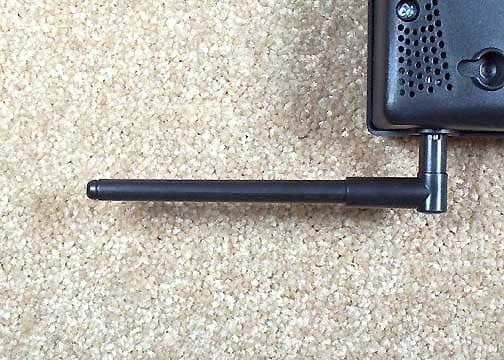
Click to zoom
Application Details
- Equipment Class
- DSS - Part 15 Spread Spectrum Transmitter
- Date of Grant
- Sep 29, 2004
- Application Purpose
- Original Equipment
- Date of Application
- Sep 29, 2004
- Equipment Note
- Integrated Vantage Pro 2 Console.
- Frequency Range
- 902.00000000 - 928.00000000
- Company
- Davis Instruments
- Country
- United States
Documents & Files
Document Text
Text extracted from the exhibit documents filed with the FCC. Open a document above to read the original.
Users Manual
Vantage Pro2 Console Manual ™ For Vantage Pro2 & Vantage Pro2 Plus Weather Stations ™™ Davis Instruments, 3465 Diablo Avenue, Hayward, CA 94545 • 510-732-9229 • www.davisnet.com Vantage Pro 2 Console Manual Rev. A, September 14, 2004 Document Part Number: 07395.234 For Vantage Pro2 Consoles # 6312 & 6312C And Vantage Pro2 Weather Stations # 6152, 6152C, 6153, 6162, 6163 Vantage Pro ® and Vantage Pro2 ™ are trademarks of Davis Instruments Corp., Hayward, CA. © Davis Instruments Corp. 2004. All rights reserved. Information in this document subject to change without notice. FCC Part 15 Class B Registration Warning This equipment has been tested and found to comply with the limits for a Class B digital device, pursuant to Part 15 of the FCC Rules. These limits are designed to provide reasonable protection against harmful interference in a residential installation. This equipment generates, uses, and can radiate radio frequency energy and, if not installed and used in accordance with the instructions, may cause harmful interference to radio communications. However, there is no guarantee that interference will not occur in a particular installation. If this equipment does cause harmful interfer- ence to radio or television reception, which can be determined by turning the equipment on and off, the user is encouraged to try to cor- rect the interference by one or more of the following measures: •Reorient or relocate the receiving antenna. •Increase the separation between the equipment and receiver. •Connect the equipment into an outlet on a circuit different from that to which the receiver is connected. •Consult the dealer or an experienced radio/TV technician for help. Changes or modification not expressly approved in writing by Davis Instruments may void the warranty and void the user's authority to operate this equipment. IC: 378810-6312 EC EMC Compliance This product complies with the essential protection requirements of the EC EMC Directive 89/336/EC. Vantage Pro2 Console Display Features Display Features 1. Compass Rose 2. Graph & Hi/Low Mode Settings 3. Forecast Icons 4. Moon Phase Indicator 5. Time/Sunrise Time 6. Date/Sunset Date 7. 2ND Button Indicator 8. Barometric Trend Arrow 9. Graph Icon 10. Current Rain Icon 11. Station Number Indicator 12. Weather Ticker 13. Graph Field 14. Alarm Icon N S WE NE SE NW SW GRAPH 2nd Vertical Scale: X10 WIND RAIN RATE in/hr DAILY in STATION NO.1 pm Last 24 hrs hr Every 1 MPH CHILL TEMP OUT HUM IN HUM OUT TEMP IN hPa BAROMETER F F F 13 14 1011 12 1 5 2 3 7 6 4 8 9 i Table of Contents Welcome to Vantage Pro2™ ........................................................... 1 Console Features ........................................................................ 1 Vantage Pro Options .................................................................. 2 Installing the Console ...................................................................... 4 Powering the Console ................................................................ 4 Installing the AC Power Adapter ............................................... 4 Installing Batteries ..................................................................... 5 Connecting Cabled Stations ....................................................... 5 Console Location ....................................................................... 6 Using Your Weather Station............................................................ 9 Setup Mode ................................................................................ 9 Current Weather Mode .............................................................. 20 Selecting Units of Measure ........................................................ 21 Displaying the Forecast.............................................................. 27 Displaying Time & Date or Sunrise & Sunset........................... 27 Calibrating, Setting, and Clearing Variables ............................. 27 Highs and Lows Mode ............................................................... 30 Alarm Mode ............................................................................... 32 Graph Mode ............................................................................... 34 Troubleshooting and Maintenance .................................................. 37 Vantage Pro2 Troubleshooting Guide ....................................... 37 Console Diagnostic Screens....................................................... 39 Console Maintenance................................................................. 42 One Year Limited Warranty ...................................................... 42 Weather Data ................................................................................... 43 Specifications................................................................................... 49 Console ...................................................................................... 49 Wireless Communication Specifications ................................... 49 Console Data Display Specfications .......................................... 50 Weather Data Specifications...................................................... 51 Vantage Pro2 Console Icons ...................................................... 53 1 Chapter 1 Welcome to Vantage Pro2™ Welcome to your Vantage Pro2 Weather Station console. The console dis- plays and records your station’s weather data, provides graph and alarm functions, and interfaces to a computer using our optional WeatherLink software. Vantage Pro2 stations are available in two basic versions: Cabled and Wireless. A Cabled Vantage Pro2 station transmits outside sensor data from the Integrated Sensor Suite (ISS) to the console using a straight- through four-conductor cable. A Wireless Vantage Pro2 station transmits outside sensor data from the ISS to the console via a low-power radio. Wireless stations can also collect data from the optional Vantage Pro2 sen- sors. See “Optiona…
Text truncated - open the document above for the full version.
Cover Letter(s)
Response to E04-000085-1 1. 78kHz clock is used in the digital circuitry only and is not associated with the transmitter, therefore testing below 14MHz is not required. 2. All tables and data sheets have correction factors. What pages are you referring to? 3. A revised users manual has been uploaded. 4. Our device 6312/6328 is one way system without feedback, it can not and will not adjust its hop table to avoid interference. 5. A revised label has been uploaded.
External Photos
Front Back Top Bottom Left Right Antenna
ID Label/Location Info
Vantage Pro2 FCC ID: IR2DWW6312 Product # 6312 3465 Diablo Avenue, Hayward, CA 94545-2778 This device complies with Part 15 of the FCC Rules. Operation is subject to the following conditions: (1) This device may not cause harmful interference. (2) This device must accept any interference received, including interference that may cause undesired operation. Mfg. Code Made in USA Final Insp. Bar. Hum. IC: Model No. May be sold under different product # as part of a larger system. 07356.165 Licensed under U.S. Patent Nos. 5,978,738, 6,076,044, and 6,597,990. Part Number: 07356.165 Ink: black Stock: Paper Radius: 0.06" Size: 4" wide x 2.25" tall (Note: Specs, except for size, should generally match 07356.165) For Printing: Top Off First, Pin Feed Vert. Dist. between labels: 0.25” Vert. Dist from top to top: 2.5” Use with Artwork File 07356.165.eps TM 0.25” 2.25” Vantage Pro2 FCC ID: IR2DWW6312 Product # 6312 3465 Diablo Avenue, Hayward, CA 94545-2778 This device complies with Part 15 of the FCC Rules. Operation is subject to the following conditions: (1) This device may not cause harmful interference. (2) This device must accept any interference received, including interference that may cause undesired operation. Mfg. Code Made in USA Final Insp. Bar. Hum. IC: Model No. May be sold under different product # as part of a larger system. 07356.165 Licensed under U.S. Patent Nos. 5,978,738, 6,076,044, and 6,597,990. TM 0.25” 2.25” 0.25” 2.25” Vantage Pro2 FCC ID: IR2DWW6312 Product # 6312 3465 Diablo Avenue, Hayward, CA 94545-2778 This device complies with Part 15 of the FCC Rules. Operation is subject to the following conditions: (1) This device may not cause harmful interference. (2) This device must accept any interference received, including interference that may cause undesired operation. Mfg. Code Made in USA Final Insp. Bar. Hum. IC: Model No. May be sold under different product # as part of a larger system. 07356.165 Licensed under U.S. Patent Nos. 5,978,738, 6,076,044, and 6,597,990. TM A RevisionChange No. Released/Revised ByDate David Read7/30/2004 Created By D. Read Date 7/30/04 Reviewer Date Document No. Revision Pages 07365.165 A 1 of 1 Label, Console, FCC, VP2 Notes: This document contains proprietary information which is the sole property of Davis Instruments Corp. This information shall not be reproduced, disclosed to third parties, or used for manufacturing without prior written authorization from Davis Instruments Corp. 4“ 378810-6312 378810-6312 378810-6312 B40922A012 B40922A013 B40922A014 6312 6312 6312 NA TG HY NA TG HY NA TG HY
Internal Photos
PCB Overall PCB Front Wide PCB Front Close PCB Front 1 PCB Front 2 PCB Front 3 Interior Back PCB Back Wide PCB Back Close
Operational Description
Expository Statement Equipment Name: Vantage Pro 2 Console/ Transceiver Model Number: 6312 Description : The 6312 is a receiver for a weather station It transmits/receives information every 2.5 seconds using Frequency Hopping Spread Spectrum technology with Frequency Shift Keying the carrier at 19200 baud rate. It hops it though 51 channels using a pseudo- random hop table though the 902-928Mhz band. And display this information in a variety of units including metric and US units. It’s power from either 3 C cell batteries or 5 volt adapter. Circuitry: The 6312 contains 1 circuit boards and an LCD display The PCBa contains the RF transmitter, Antenna: The antenna is 4” helical copper wire inside a 4” long plastic housing. It makes approximately a ¼ wave dipole with the ground plane of the board.
Test Report
Page 1 of 45 Report No: FC04-068 DAVIS INSTRUMENTS TEST REPORT FOR THE VANTAGE PRO 2 CONSOLE, 6312 FCC PART 15 SUBPART B SECTIONS 15.107 AND 15.109 CLASS B AND SUBPART C SECTIONS 15.207, 15.209 & 15.247 COMPLIANCE DATE OF ISSUE: SEPTEMBER 9, 2004 PREPARED FOR: Davis Instruments 3465 Diablo Avenue Hayward, CA 94545 PREPARED BY: Mary Ellen Clayton CKC Laboratories, Inc. 5473A Clouds Rest Mariposa, CA 95338 P.O. No.: W.O. No.: 57173 82619 Date of test: August 27 – September 1, 2004 Report No.: FC04-068 This report contains a total of 45 pages and may be reproduced in full only. Partial reproduction may only be done with the written consent of CKC Laboratories, Inc. The results in this report apply only to the items tested, as identified herein. Page 2 of 45 Report No: FC04-068 TABLE OF CONTENTS Administrative Information .............................................................................................4 Summary of Results .........................................................................................................5 Conditions for Compliance ..............................................................................................5 Approvals .........................................................................................................................5 Equipment Under Test (EUT) Description ......................................................................6 FCC 15.31(e) Voltage Variation......................................................................................6 FCC 15.31(m) Number Of Channels ...............................................................................6 FCC 15.33(a) Frequency Ranges Tested .........................................................................6 FCC 15.35 Analyzer Bandwidth Settings ........................................................................6 FCC 15.203 Antenna Requirements ................................................................................6 FCC 15.205 Restricted Bands..........................................................................................6 Eut Operating Frequency .................................................................................................6 Equipment Under Test .....................................................................................................7 Peripheral Devices ...........................................................................................................7 Report of Measurements ..................................................................................................8 Table 1: FCC 15.107 Six Highest Conducted Emission Levels ..........................8 Table 2: FCC 15.109 Six Highest Radiated Emission Levels .............................9 Table 3: FCC 15.207 Six Highest Conducted Emission Levels ..........................10 Table 4: FCC 15.209 Six Highest Radiated Emission Levels: 30-1000 MHz.....11 Table 5: FCC 15.209 Six Highest Radiated Emission Levels: 1-10 GHz ...........12 FCC 15.247(a)(1) Frequency Separation .............................................................13 FCC 15.247(a)(1) Hopping Channels ..................................................................14 FCC 15.247(a)(1)(i) Average Time Of Occupancy .............................................15 Table 6: FCC 15.247(b)(3) Six Highest Radiated Emission Levels ....................17 FCC 15.247(c) Emissions Mask ..........................................................................18 20dB Bandwidth ..................................................................................................19 Temperature And Humidity During Testing....................................................................22 EUT Setup........................................................................................................................22 Correction Factors............................................................................................................22 Table A: Sample Calculations .............................................................................22 Test Instrumentation and Analyzer Settings ....................................................................23 Spectrum Analyzer Detector Functions ...............................................................23 Peak..........................................................................................................23 Quasi-Peak ...............................................................................................23 Average ....................................................................................................23 EUT Testing.....................................................................................................................24 Mains Conducted Emissions................................................................................24 Radiated Emissions ..............................................................................................24 Page 3 of 45 Report No: FC04-068 Appendix A: Test Setup Photographs..............................................................................25 Photograph Showing Radiated Emissions ...........................................................26 Photograph Showing Radiated Emissions ...........................................................27 Photograph Showing Conducted Emissions ........................................................28 Appendix B: Test Equipment List ...................................................................................29 Appendix C: Measurement Data Sheets ..........................................................................30 Page 4 of 45 Report No: FC04-068 ADMINISTRATIVE INFORMATION DATE OF TEST: August 27 – September 1, 2004 DATE OF RECEIPT: August 27, 2004 PURPOSE OF TEST: To demonstrate the compliance of the Vantage Pro 2 Console, 6312, with the requirements for FCC Part 15 Subpart B Sections 15.107 and 15.109 and Subpart C …
Text truncated - open the document above for the full version.
Test Setup Photos
PHOTOGRAPH SHOWING RADIATED EMISSIONS Radiated Emissions - Front View PHOTOGRAPH SHOWING RADIATED EMISSIONS Radiated Emissions - Back View
Contact Information
Applicant
Bruce Walter(Sr Design Engineer)
Technical Contact
CKC Laboratories, Inc.MaryEllen Clayton
[email protected]209-966-5240
5473A Clouds Rest · Mariposa, California · United States
Non-Technical Contact
CKC Laboratoires, Inc.MaryEllen Clayton
[email protected]209-966-5240
Test Firm
CKC Laboratories, Inc.Steve Behm
Technical Specifications
| # | Rule Parts | Frequency Range | Power Output |
|---|---|---|---|
| 1 | 15C | 902 MHz - 928 MHz | 1.30 mW |
Other Applications from Davis Instruments
IR2DWW6313U
Jan 03, 2023WeatherLink Console
Equipment Class
DTS - Digital Transmission System
IR2DWW765Y
Jun 09, 2005Vantage Pro 2 Wireless Repeater
Equipment Class
DSS - Part 15 Spread Spectrum Transmitter
IR2DWW6345
Mar 13, 2005Measurement Station
Equipment Class
DSS - Part 15 Spread Spectrum Transmitter
IR2DWW6328
Sep 29, 2004Integrated Sensor Suite 2 with SPARS
Equipment Class
DSS - Part 15 Spread Spectrum Transmitter
IR2DWW6361
Aug 19, 2001Soil Moisture Station, 6361
Equipment Class
DXX - Part 15 Low Power Communication Device Transmitter